UNIVERSITÉ DE SHERBROOKE Faculté de génie
Département de génie civil
Investigation of the higher mode effects on the dynamic behaviour of
reinforced concrete shear walls through a pseudo-dynamic hybrid test.
Étude de l’effet des modes supérieurs sur le comportement dynamique des murs de refend en béton armé à l’aide d’un essai pseudo-dynamique avec sous-structure.
Thèse de doctorat ès Sciences Appliquées Spécialité: génie civil
Hassan Fatemi
Composition du jury: Patrick PAULTRE (directeur)
Charles-Philippe LAMARCHE (codirecteur) Denis MITCHELL
Jacky MAZARS
Résumé
La plupart des bâtiments de moyenne et grande hauteur en béton armé sont munis de murs de refend ductiles afin résister aux charges latérales dues au vent et aux séismes. Les murs de refend ductiles sont conçus selon des règles conception stricts. Ces murs sont généralement conçus de façon à forcer la formation d’une rotule plastique à leur base dans l’éventualité d’un séisme majeur. Lors de la conception d’un mur, l’enveloppe des moments fléchissants ainsi que l’enveloppe des efforts tranchants dans la portion du mur situé au-dessus de la rotule plastique sont basés sur la résistance probable en flexion du mur dans la région de la rotule plastique. Plusieurs études sur les murs de refend conçus selon cette philosophie de conception on fait le constat que l’effort tranchant maximum dans un mur peut être sous-estimé lors d’un séisme, et que des rotules plastiques peuvent également se former à d’autres endroits qu’à la base du mur, ce qui constitue un mécanisme de ruine indésirable. Ces effets sont principalement attribuables à la contribution des modes supérieures à la réponse dynamique globale des bâti-ments lors d’un séisme. L’effet des modes supérieurs est particulièrement important dans les bâtiments élancés de grande hauteur ayant une période propre de vibration longue.
L’essai pseudo-dynamique avec sous-structure est une méthode efficace et économique d’évaluer expérimentalement l’effet des modes supérieurs sur le comportement sismique des murs de refend dans les bâtiments. Lors de tels essais, comme la masse du bâtiment est modélisée numériquement, ceci permet de tester des structures à de relativement grandes échelles sans avoir à combattre mécaniquement les forces d’inerties générées lors d’un séisme. Dans le cadre de la présente étude, la portion constituant la base d’un mur de refend correspondant à la zone de rotule plastique faisant partie d’un bâtiment de huit étages à l’échelle 1/2,75 a été testé. Les dimensions générales de la portion de mur testée étaient de 1800 mm de longueur, par 2200 mm de hauteur par 160 mm d’épaisseur. Le mur étudié a été conçu selon l’édition 2015 du Code National du Bâtiment du Canada (CNBC 2015) ainsi que selon la norme CSA A23.3-14 (Calcul des ouvrages en béton), où le facteur d’amplification de l’effort tranchant causé par l’effet des modes supérieurs n’a pas été pris en compte.
Lors des essais pseudo-dynamiques avec sous-structure, une nouvelle méthode de contrôle à trois degrés de liberté convenant à des spécimens d’essai très rigides axialement a été dévelop-pée et validée. Une procédure novatrice de redémarrage d’un essai interrompu en cours de route a également été développée et validée. Lors des essais, le bâtiment de huit étages inclu-ant la portion de mur dans le laboratoire a été soumis à trois séismes. Le premier séisme était de très faible intensité, l’intensité du deuxième séisme correspondait au séisme de conception, et le troisième séisme correspondait au séisme de conception dont l’intensité a été doublé. Du-rant les deux séismes de forte intensité, le mur testé s’est comporté de manière ductile et des fissures de cisaillement et de flexion importantes ont été observées. Même si l’effort tranchant maximum mesuré durant le séisme de conception a atteint 2,16 fois la valeur de conception du mur, et 3.01 fois la valeur de conception du mur dans le cas du séisme amplifié, aucun mé-canisme de ruine n’a été observé. Suite aux essais pseudo-dynamiques avec sous-structure, un essai par poussée progressive a également été effectué.
Les résultats des essais pseudo-dynamiques avec sous-structure portent à croire que la valeur de l’effort tranchant de conception d’un mur selon la norme CSA A23.3-14 est sous-estimé. De plus, l’essai poussée progressive a permis de démontrer que le mur était beaucoup plus résistant qu’anticipé, puisque l’effort tranchant avait été sous-estimé lors de la conception. L’essai par poussée progressive a également permis de démontrer que le mur peut atteindre des niveaux de ductilité en déplacement supérieur à celui prévu par la norme CSA A23.3-14.
Mots-cles : amplification dynamique des modes supérieurs, murs ductiles en béton armé, essai hybride, contrôle de déplacement et de force.
ABSTRACT
Most mid- and high-rise reinforced concrete (RC) buildings rely on RC structural walls as their seismic force resisting system. Ductile RC structural walls (commonly called shear walls) designed according to modern building codes are typically detailed to undergo plastic hinging at their base. Both the design moment envelope for the remaining portion of the wall and the design shear forces are evaluated based on the probable flexural resistance of the wall in the plastic hinge region. Several analytical studies have shown that so-designed structural walls can be subjected to shear forces in excess of the design values. Plastic hinging can also develop in the upper portion of the walls. These effects are mainly attributed to higher mode response and, hence, are more severe in taller or slender walls with long fundamental periods. Consid-ering the literature, there is a significant uncertainty regarding the behavior of the structural walls under the higher mode of vibrations excited under earthquake excitations.
Hybrid testing is an effective experimental method to study the natural behaviour of structures such as shear walls. The hybrid testing method enables the simulation of the seismic response of large structural elements like RC shear walls without the need to include large masses typ-ically encountered in multi-storey buildings. In this study a barbell shaped RC shear wall specimen of 1800 mm in length including a 300 mm × 300 mm boundary element at each end that is 2200 mm in height, and 160 mm thick was investigated. A test specimen corresponding to the base plastic hinge zone of an 8-storey shear wall was tested in a laboratory evolvement whilst the reminder of the building structure was modeled numerically. The reference wall was scaled down by a factor of 1/2.75 to obtain dimensions of the test specimen. The RC wall was designed in accordance with the 2015 edition of the National Building Code of Canada (NBCC 2015) and the Canadian Standard Association A23.3-14 code. The amplification of the base design shear force accounting for the inelastic effects of higher modes specified by the CSA A23.3-14 standard was not taken into account in order to evaluate the amplification ex-perimentally.
In order to investigate the response of ductile RC walls under earthquake ground motions and track the effect of the higher vibration modes on the shear force demand, three earthquakes with different intensities were applied on the hybrid model successively. The RC wall exhib-ited a ductile behaviour under the ground motions and flexural and shear cracks developed all over the height of the wall. In spite of amplifying the shear force demand by a factor of 2.16 under the design level earthquake and 3.01 under a high intensity earthquake, no shear failure was observed. The test results indicated that the amplification of the design shear forces at the base of ductile RC shear walls are underestimated by the CSA A23.3-14 standard.
A new method for controlling three degrees of freedom in hybrid simulation of the earthquake response of stiff specimens was developed and verified in this study. Also, an innovative pro-cedure to restore an interrupted hybrid test was programmed and verified.
The hybrid tests were followed by a push-over test under a lateral force distribution equal to the square root of sum of the squares of the first five modes in order to evaluate the dis-placement ductility of the RC wall. Findings of the final push-over test showed that the tested ductile RC wall can withstand higher displacement ductilities than the presented levels in the NBCC 2015.
Keywords: dynamic amplification of higher modes, ductile reinforced concrete shear wall, hybrid test, force and displacement control method.
Acknowledgements
I would like to gratefully and sincerely thank my directors Prof. Patrick Paultre and Prof. Charles Philippe Lamarche for their guidance, support, understanding, patience, and most im-portantly, their friendship during my graduate studies at Université de Sherbrooke. Without their support and advices this thesis could never see the light of day. It is whole-heartedly ex-pressed that your advices for my research proved to be a landmark effort towards the success of my project.
I would like to offer my special thanks to all the people who created such a good atmospher in the Laboratory of Structures; Jeason Desmarais, Éric Beaudoin, Claude Aubé, and Raphaël Prévost. Assistance provided by Jeason Desmarais and Éric Beaudoin in designing and making three different, large scale, and complex test set-ups was greatly appreciated.
I wish to present my special thanks to Dr Andreas Schlenberg and Dr Frank McKenna. They provided me with very valuable helps in replying my emails asking about OpenSees and Open-Fresco programs. I would like to show my gratitude to Dr Ali Davaran who was eagerly dis-cussing with me about solving both theoretical and experimental problems in my thesis. To all my dear friends and colleagues in Sherbrooke, thank you for your understanding and encouragement in my difficult times. Yannick Boivin, Steeve Ambroise, Olivier Gauron, Alex Loignon, . . . , your friendship and cooperation made my stay at Sherbrooke a very wonderful experience. It is not possible to list all the names here, but you are always on my mind. I wish to acknowledge the help provided by Wilsonne François and Gabriel Rivard during the tests. They kindly allocated a long time in helping me to manage the tests and recording test data. I thank all those whose assistance proved to be a milestone in the accomplishment of my end goal.
Finally, and the most importantly, I would like to express my very great appreciation to my wife Somayyeh. Her support, encouragement, quiet patience and unwavering love were un-deniably the bedrock upon which the past five years of my life have been built. I have to thank my parents for their love and continuous support throughout my life. My father always taught me that if you work hard, it would eventually pay off, and my mother thought me how to stay hopeful in hard times. Thank you both for your hard working at every moment of your life to support me, my sisters and my brothers.
"Science is about knowing, Engineering is about doing." -Henry Petroski
Contents
Résumé i
Acknowledgements v
List of Figures xi
List of Tables xv
List of Symbols xvii
List of Acronyms xix
1 Introduction 1
1.1 General concept . . . 1
1.2 Problem description . . . 2
1.3 Research objectives . . . 3
1.4 Document organization . . . 4
1.5 Research originality and importance . . . 4
2 Hybrid Simulation and Control Methods 7 2.1 Introduction . . . 7
2.2 Hybrid test background . . . 7
2.3 Control methods . . . 8
2.4 Sources of errors and error propagation . . . 12
2.5 Integration methods . . . 15
3 Literature Review of Higher Mode Effects in RC Structural Walls 17 3.1 Introduction . . . 17
3.2 Dynamic behavior of RC structural walls . . . 18
3.3 Higher mode effects . . . 21
3.4 Higher mode amplification factors . . . 24
3.5 Experimental studies . . . 32
3.6 Design codes and standards . . . 33
4 Test Program 39 4.1 Introduction . . . 39
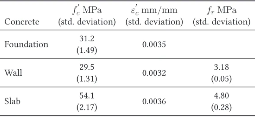
4.2 Material Properties . . . 39
4.3 Shear wall of the reference building . . . 42
4.4 Scaling factor . . . 48
4.5 Scaled shear wall . . . 48
4.6 Instrumentation . . . 53
4.7 Wall segments . . . 57
4.8 Test set up . . . 60
5 Numerical Modeling of Shear Walls 63 5.1 Introduction . . . 63
5.2 Modeling approaches . . . 63
5.3 Damping . . . 66
5.6 Numerical models for the current study . . . 77
5.7 Summary . . . 83
6 Hybrid Tests 85 6.1 Introduction . . . 85
6.2 Test setups . . . 85
6.3 Hybrid model of the RC wall . . . 88
6.4 Integration algorithm, time step, and damping . . . 92
6.5 Architecture of the control program . . . 92
6.6 Controlling horizontal and rotational Dofs . . . 94
6.7 Control procedure . . . 94
6.8 Restart of an interrupted nonlinear hybrid test . . . 98
7 Test Results and Discussion 103 7.1 Introduction . . . 103
7.2 Experimental stiffness . . . 103
7.3 Ground motions . . . 104
7.4 Structural response . . . 105
7.5 Predictions of shear force capacity . . . 121
7.6 Higher mode effects . . . 121
7.7 Decomposition of the deformation mechanisms . . . 128
7.8 State of the wall after the hybrid tests . . . 136
7.9 Controlling errors during the hybrid tests . . . 137
7.10 Push-over test . . . 139
7.11 Displacement ductility . . . 143
7.12 Summary . . . 144
8 Test Results versus Numerical Simulations 145 8.1 Introduction . . . 145
8.2 Shear force and flexural moment demands . . . 145
8.3 Summery . . . 152
9 Conclusion and Future Research 153 9.1 Conclusion . . . 153
9.2 Future research . . . 155
A Seismic Design Forces 157 A.1 Amplification factors for flexural moments . . . 157
A.2 Amplification factors for shear forces . . . 158
B OpenSees/OpenFresco code 161
Bibliography 169
List of Figures
1.1 Charlevoix region seismicity, natural resources Canada [143]. . . 3
2.1 Displacement control. . . 9
2.2 Mixed Force-Displacement control. . . 12
2.3 Typical two degrees of freedom test setups. . . 13
3.1 Dynamic model of a shear wall seismic displacements, and modes shapes. . . 18
3.2 Failure modes of a cantilever wall. . . 20
3.3 Stable hysteretic response of a ductile wall structure. . . 21
3.4 Hysteretic response of a structural wall controlled by shear strength. . . 21
3.5 Lateral seismic force distribution. . . 23
3.6 Mean results from the parametric study of Rutenberg and Nsieri. . . 29
3.7 Design envelope of the shear forces over the building height. . . 30
3.8 Capacity design envelopes. . . 31
3.9 Four distributions of seismic shear force . . . 37
4.1 Stress-Strain diagrams of the reinforcing steels. . . 41
4.2 Stress-Strain diagrams of the concrete at 28 days. . . 42
4.3 Minimum wall thickness in the plastic hinge zone. . . 44
4.4 Bottommost section of the reference wall. . . 45
4.5 Sectional analysis of the reference RC wall . . . 46
4.6 Wall design flexural moment and section resistances. . . 47
4.7 Design shear and section resistances. . . 47
4.8 Test specimen . . . 50
4.9 Test specimen sectional analysis . . . 51
4.10 Foundation section dimensions and reinforcement. . . 52
4.11 Pouring of the concrete into the foundation forms. . . 52
4.12 Transversal and longitudinal reinforcements in the slab. . . 53
4.13 Top steel beam and its connection to the reinforced slab. . . 54
4.14 Internal vertical strain gauges, names and positions. . . 55
4.15 Internal horizontal strain gauges, names and positions. . . 56
4.16 External instrumentation, the north side. . . 57
4.17 External instrumentation, the south side. . . 58
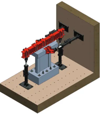
4.18 Isometric view of the test set-up and the specimen. . . 60
4.19 Side view of the test set-up. . . 61
5.1 Reinforced concrete membrane element . . . 64
5.2 Shear and flexural deformation of a cantilever element. . . 65
5.3 Rayleigh mass and stiffness proportional damping. . . 67
5.4 Pre- and post-peak compression response of concrete used in the VT2 models. . . 68
5.5 Liner tension softening response used in the VT2 models. . . 69
5.6 Steel02 material stress-strain behaviour . . . 70
5.7 Reinforcing steel backbone stress-strain behaviour . . . 70
5.8 Concrete02 material stress-strain behaviour . . . 71
5.9 Concrete04 material stress-strain behaviour . . . 72
5.10 Shear walls tested by Chen . . . 73
5.11 Fiber element model of the RC wall . . . 74
5.12 Shear walls tested by Ghorbanirenani . . . 76
5.13 OpenSees model and Ghorbaninrenani test results . . . 77 xi
5.16 VT2 and OS numerical model results for base flexural moment . . . 81
5.17 VT2 and OS numerical model results for flexural moment demand at top . . . 81
5.18 VT2 and OS numerical model results for horizontal displacement . . . 82
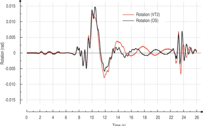
5.19 VT2 and OS numerical model results for rotation demand . . . 82
5.20 T2 and OS numerical model results for rotation demand at roof . . . 83
6.1 Test setup for pretest I. . . 86
6.2 Single and double steel box sections. . . 86
6.3 Test setup for pretest II using four jacks for axial load. . . 87
6.4 Test setup for pretest II using two jacks for axial load. . . 88
6.5 3D view of the final test setup . . . 89
6.6 Photo of the final test setup. . . 89
6.7 Two dimensional cantilever beam with three degrees of freedom. . . 90
6.8 Architecture of the communication and control procedure. . . 93
6.9 Section deformation considering Euler-Bernoulli assumptions. . . 95
6.10 Compressive area depth and section curvature . . . 96
6.11 Scaling procedure during the test . . . 97
6.12 PID controller terms. . . 98
6.13 Communication and control procedure of hybrid test . . . 100
7.1 Successive displacement response time histories . . . 106
7.2 Time histories of the reference wall responses in force (successive) . . . 107
7.3 Test specimen displacement response under GM0 . . . 109
7.4 Shear and moment demands of reference wall under GM0 . . . 110
7.5 Test specimen displacement response under GM1 . . . 111
7.6 Shear and moment demands of reference wall under GM1 . . . 112
7.7 Developing first flexural crack . . . 113
7.8 Crack pattern right after first yielding on vertical steels . . . 113
7.9 Crack pattern corresponding to the first diagonal crack . . . 115
7.10 Crack pattern after the first yielding in horizontal steels . . . 115
7.11 Yielding pattern measured in longitudinal under the GM1 excitation. . . 116
7.12 Yielding pattern measured in horizontal bars under the GM1 excitation. . . 116
7.13 Crack pattern at the end of GM1 excitation. . . 117
7.14 Test specimen displacement response under GM2 . . . 118
7.15 Shear and moment demands of reference wall under GM2 . . . 119
7.16 Yielding pattern measured in longitudinal bars under the GM2 excitation. . . 120
7.17 Yielding pattern measured in horizontal bars under the GM2 excitation. . . 120
7.18 Test results versus the predicted maximum shear amplification . . . 123
7.19 Time histories of flexural moment of the reference RC wall . . . 124
7.20 Reference wall deformation modes under the GM1 excitation . . . 125
7.21 Reference wall deformation modes in peak points . . . 126
7.22 Positive and negative flexural moment demand . . . 127
7.23 History of foundation sliding. . . 129
7.24 Sliding in the base sliding zone of the wall (segment I). . . 130
7.25 Rotation history in the wall base sliding zone (segment I). . . 131
7.26 Displacement decomposition concept . . . 132
7.27 Displacement decomposition under the GM1 excitation . . . 134
7.28 Displacement decomposition at top of the segment III under GM2 . . . 135
7.29 State of the wall after the GM1 excitation. . . 136
7.30 State of the wall after the GM2 excitation. . . 137
7.31 Loose broken concrete after hybrid tests . . . 137
7.32 History of the displacement error at the control point. . . 138
7.33 History of the rotation error at the control point. . . 138
7.34 Lateral force modal distribution . . . 140
7.35 Loading protocol of the push-over test . . . 140
7.36 Base shear force versus horizontal displacement . . . 141
7.37 Base flexural moment versus rotation . . . 141
7.38 Bar buckling and loose broken concrete after push-over test . . . 142
7.39 Rotation corresponding with the base yielding flexural moment . . . 143
8.1 Test results versus OS . . . 146
8.2 Test results versus VT2 . . . 147
8.3 Test results versus numerical models under the excitation GM0. . . 149
8.4 Test results versus numerical models under the excitation GM1. . . 150
8.5 Test results versus numerical models under the excitation GM2. . . 151
List of Tables
3.1 Isolated cantilever shear walls studied by Ghosh . . . 27
4.1 Mechanical properties of the used reinforcing steels. . . 40
4.2 Mechanical properties of the used concretes at the age of 28 days. . . 40
4.3 Mass distribution. . . 43
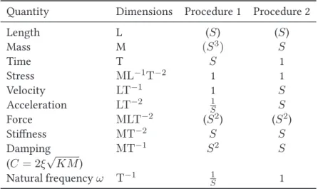
4.4 Scale factors used in pseudo-dynamic test . . . 48
5.1 Effective shear stiffness factors for Ghornabirenani’s walls. . . 75
5.2 Effective shear stiffness factors for reference wall. . . 78
7.1 Scale up factors for the experimental stiffness. . . 104
7.2 Design forces and experimental demands. . . 121
7.3 Dynamic amplification factors. . . 122
7.4 Maximum measured foundation sliding under the seismic excitations. . . 128
A.1 Factored flexural moments and base shear forces. . . 157
A.2 Design flexural moments envelope. . . 158
A.3 Seismic design forces of the reference RC wall. . . 159
List of Symbols
A cross sectional areaAg gross concrete section area
As cross sectional area of reinforcement steel
c depth of neutral axis
D diagonal length
D1mrsd measured length of diagonal potentiometer D2mrsd measured length of diagonal potentiometer
D1shear diagonal elongation/shrinkage due to pure shear deformations D2shear diagonal elongation/shrinkage due to pure shear deformations de average stroke of vertical LVDTs located on the east side
dw average stroke of vertical LVDTs located on the west side
fy yielding stress of reinforcing steel
fu ultimate tensile stress of reinforcing steel
f′
c compressive strength of concrete at 28 days of age
g acceleration of earth’s gravity field
h height
hp height of base plastic hinge
hw total height of wall
kp proportional gain
ki integral gain
kd derivative gain
l length
lw wall length
Mn nominal flexural resistance of section
Mp probable flexural resistance of section
Mr factored flexural resistance of section
My Yielding flexural moment of section
P axial force
Ro over strength related force reduction factor
Rd ductility related force reduction factor
T1 fundamental period of building
Ubs displacement due to sliding of the base sliding zone
Ubzr displacement due to rotation of the base sliding zone
Uf lex/Uf flexural displacement
Ush shear displacement
UT total displacement
Vd design shear force
Vf factored shear force
Vp shear force corresponding to development of base plastic hinge
Vr factored shear resistance
α relative distance from top of a given segment to centroid of rotation of that layer
φ section curvature
θbsz base sliding zone rotation
θsegII rotation of the segment II
θsegIII rotation of the segment III
ω & ωv shear amplification factor
γ correction factor
List of Acronyms
ACI American Concrete Institute AIJ Architectural Institute of Japan
ASTM American Society for Testing Material CSA Canadian Standard Association
DCH Ductility Class High DCL Ductility Class Medium DOF Degree Of Freedom EC8 Euro Code 8
FEM Finite Element Model
FRQNT Fonds de Recherche du Québec Nature et Technologies GM0/1/2 Ground Motion number 0/1/2
LD Long Duration
LVDT Linear Variable Differential Transformer MCFT Modified Compression Field Theory NBCC National Building Code of Canada NSC Normal Strength Concrete
NSERC Natural Science and Engineering Research Council of Canada NZS New Zealand Standard
OS OpenSees
PGA Peak Ground Acceleration PID Proportional/Inegral/Derivative PSD Pseudo Dynamic
R2000 Response 2000 RC Reinforce Concrete SD Short Duration
SFRS Side Force resistant System SRSS Square Root of Sum of Squares
TCP/IP Transmission Control Protocol/Internet Protocol UHS Uniform Hazard Spectra
VT2 VecTor2
Chapter 1
Introduction
1.1 GENERAL CONCEPT
Civil engineering structures are designed to resits probable natural hazards. One of the most important type of hazards are earthquakes. For each civil engineering structure a suitable seis-mic force resisting system (SFRS) is used to resist seisseis-mic events. Structural walls, commonly called shear walls, are often used as a SFRS system in multi-storey buildings structures. The usefulness of structural walls in building structures to resist seismic forces has long been recognized by the engineering community. For buildings up to 20 stories high, the use of struc-tural walls is often a matter of choice. For buildings over 30 stories high, the use of strucstruc-tural walls may become inevitable from an economical point of view, and also, for the control of lat-eral deflections [160]. Fintel [59] has described observations of the performance of structural walls under severe earthquakes where modern reinforced concrete buildings stood the test of violent shaking. An important observation by Fintel [59] is that buildings containing struc-tural walls have exhibited satisfactory earthquake performances in comparison with concrete framed structures. According to Fintel, no collapse of buildings with structural walls used as SFRS system has ever been reported. It is of interest to note that most of structures studied by Fintel were designed in a traditional manner for gravity loads and overturning moments without considering earthquake loads and therefore without special detailing for ductility as required by modern building codes.
Ductile response of structural walls under strong seismic ground motions can be achieved through the development of a flexural plastic hinge at the base of the wall if horizontal shear forces over the height of the building are resisted adequately. When analyzing reinforced con-crete buildings with structural walls under earthquake loads, it is generally assumed that each floor acts as a rigid in-plane diaphragm and transmits the inertial forces directly to the wall. It is also generally assumed that the rigidity of an RC wall is not influenced by the strength and stiffness of its foundation (the foundation is assumed to be infinitely rigid). In most structures that are subjected to moderate-to-strong ground motions, earthquake resistance is achieved by allowing yielding to take place in some structural members. It is generally impractical as well as uneconomical to design a structure to respond in the elastic range to the maximum expected earthquake-induced forces. Therefore, in seismic design, yielding is permitted in
predetermined structural members at selected locations with the provision that the vertical load-carrying capacity of the structure is maintained even after strong ground motions. It is through technical and structural developments in earthquake engineering that building codes, design standards, and seismic provisions are being updated. Still there are aspects that are not completely understood due to the random nature of earthquakes as well as the complex nature of the response of reinforced concrete structures. Among these aspects, higher mode effects on the nonlinear dynamic behavior of structures during ground motions is an important issue [24, 61].
1.2 PROBLEM DESCRIPTION
Ductile reinforced concrete shear walls designed according to modern building codes are typi-cally detailed to undergo plastic deformations at their base. Both the design moment envelope for the remaining portion of the wall and the design shear forces are evaluated based on the probable flexural resistance of the wall in the plastic hinge region. Several analytical studies have shown that so-designed structural walls can be subjected to shear forces in excess of the design values. Nonlinear time history dynamic analysis of shear walls subjected to earthquake ground motions have shown that due to the contribution of higher modes in the global re-sponse, shear forces in excess of these capacity design values can develop [8, 24, 57, 159, 214]. These high shear forces can lead to brittle shear and/or sliding failure modes. Plastic hinges can also develop in the upper portion of the walls [61]. These undesirable failure modes are mainly attributed to the contribution of the higher modes to the global response and, hence, are more severe in taller or slender building structures with long fundamental periods [170]. The value of the fundamental period and the flexural overstrength at the wall base greatly af-fect the dynamic shear amplification and seismic force demand [25].
Testing of reinforce concrete (RC) shear wall specimens under dynamically applied high fre-quency content records should allow for the validation of the shear and bending moment de-mand on structural walls, including higher mode effects, and the interaction between shear and flexure inelastic responses. In the past, while the static behavior of reinforced concrete shear walls has been the subject of numerous studies, the same cannot be said for the behav-ior of RC shear walls under dynamic loads [119]. Consequently, appropriate test methods to investigate the dynamic response of these structural elements have been recently developed. In this research, synthetic earthquake time histories generated by Atkinson [14] for eastern Canada, scaled to the unform hazard spectrum of the city of Rivière-du-Loup NBCC 2015 [146] were used. Rivière-du-Loup is located in the Charlevoix region that is a very high seismic risk area in Quebec (see Figure 1.1).
prin-1.3. Research objectives 3 ciples, defined by the National Building Code of Canada (NBCC 2015) [146] and the Canadian Standard Association concrete design standard A23.3 (CSA A23.3) [46]. By use of capacity de-sign principles, the potential plastic mechanisms within a structure are clearly defined. Then, undesirable modes of failures, e.g. shear failures, are avoided by ensuring that the strength of the elements against those modes are sufficient. The remainder of the structural elements are designed to remain elastic without considering the intensity of the ground shaking or the magnitudes of ground motions [160].
Figure 1.1: Charlevoix region seismicity, natural resources Canada [143].
1.3 RESEARCH OBJECTIVES
This research project aims at experimentally investigating the effects of higher modes on re-inforced concrete shear walls subjected to earthquake excitations. The main objective of the research is to experimentally study the seismic behavior in the plastic hinge zone of RC shear walls located in high-rise buildings through a hybrid test. Eastern North American ground motion records, which are rich in high frequencies, and present a more critical condition for higher mode response, were used. From a general point of view, this study characterizes ex-perimentally:
1. the seismic shear and flexural demands of the tested cantilever structural wall; 2. the damage at the base of the tested wall;
3. the influence of inelastic shear amplification caused by the higher modes of vibration on the seismic behavior of the wall;
4. the failure modes of the ductile structural wall designed according to the capacity design principals.
1.4 DOCUMENT ORGANIZATION
This thesis comprises eight chapters based on the regulations of Université de Sherbrooke concerning traditional PhD thesis. Chapter one provides a brief definition of the problem and explains the objectives of the research. The second chapter addresses the hybrid testing tech-nique, control methods, and error sources. Chapter three is a literature review about the seis-mic behaviour of RC shear walls, higher mode effects, and code equations to consider higher mode effects in designing RC shear walls. Chapter four describes the test program, the mate-rial used in construction of the test specimen, and the internal and the external measurement instrumentation. Chapter five describes numerical models of RC shear walls necessary to pro-vide a reliable numerical model to carry out a hybrid test. Chapter six presents the hybrid test set-up, a new control procedure to control RC structural elements with a combination of displacement and force control methods, and a new method to restart an interrupted nonlin-ear hybrid test. Test results and structural behaviour of the RC wall are explained in Chapter seven. In this chapter the final push-over test, hysteretic behaviour of the specimen, and the achieved displacement ductility level are presented. Chapter eight compares the test results against the numerical predictions from shell and fiber elements models. This chapter addresses the capability of each numerical model in simulating the seismic behaviour of RC walls. Chap-ter nine presents important results of the hybrid tests and also the push-over test. This chapChap-ter provides recommendations and conclusions about the research project.
1.5 RESEARCH ORIGINALITY AND IMPORTANCE
The main important scientific contribution of this research lies in the experimental verification of the effects of higher modes on the structural behaviour of a cantilever RC shear wall through a hybrid test by controlling three degrees of freedom (two translational and one rotational). The following points summarize the scientific contributions of the research:
1. Experimentally qualifying the effects of higher modes on the shear force demand of can-tilever RC shear walls designed according to CSA A23.3-14 [46].
1.5. Research originality and importance 5 2. Developing a new control approach to perform hybrid tests with a combination of force
and displacement control methods.
3. Restoring an interrupted hybrid test using previously recorded data.
4. Evaluating the displacement ductility of RC shear walls through a push-over test. 5. Assessing the capabilities of the shell and fiber element numerical models in predicting
the seismic behaviour of RC shear walls.
The test results provided a better understanding of the effect of the higher modes on RC struc-tural walls’ shear force demand and demonstrated the interaction between shear and flexural deformations in the response. Results showed that higher modes have a profound effect on the magnification of the structural walls’ shear force demand.
Chapter 2
Hybrid Simulation and Control Methods
2.1 INTRODUCTION
Hybrid simulations combine numerical models and experimental testing techniques using ad-vanced control methods for the efficient and realistic evaluation of the seismic performance of structural elements. A given structural system is divided in two parts, a numerical and a physical substructure and discrete parts of the equation of motion for the whole structure are extracted from relevant subassembly, and then integrated. During a hybrid test, structural ele-ments with a well-understood behavior are usually modeled numerically while eleele-ments with complex nonlinear behavior are tested physically. In this test method, the target displacements are applied quasi-statically or in real time to the physical substructure, and the restored forces in the physical subassembly, measured experimentally, are fed back to the numerical model to continue the analysis in the next step. The hybrid testing method has the potential for combining the economy and versatility of conventional quasi-static testing with the realism of shaking table tests.
Hybrid tests can be performed in real time or quasi-statically. The main advantage of the real time tests is considering all time dependent effects of the experimental subassembly such as inertia forces, damping, and strain rate effects.
Pseudo Dynamic (PSD) tests are performed on an expanded time-scale. This simplifies the re-quired equipments, allows for inspection of the specimen between load steps, and reduces the complexity of the control methods. The major potential drawback of the PSD test method is that time-dependent behaviors are not taken into account. Also relaxation phenomena in this expanded time may induce some errors.
2.2 HYBRID TEST BACKGROUND
Over the past four decades hybrid simulation methods have evolved considerably, moving from very simple single degree of freedom to more complex structures, and from ramp and hold to more realistic continuous and real-time loading [132]. The hybrid testing concept originated in 1969 with Hakuno et al. [71]. Hakuno et al. studied a cantilever beam using an electromagnetic actuator controlled by an analog computer. This experiment had rather
poor results because of the low accuracy and limitations of the available control technology. Takanashi et al. [202] refined Hakuno’s idea. The new method, called online testing, used a digital computer that generated more accurate results. A year after, Takanashi et al. [200] adopted the central difference explicit integration method to perform hybrid tests. The first structure that was tested is a two-story single-bay steel frame. Mochizuki [126] performed a hybrid test to study soil-structure interaction of a pile embedded in soil. The first hybrid test on a reinforced concrete structural element, an RC column, was performed by Okada et al. [154]. During a decade and half following the first development of the hybrid testing method, almost 27 studies were conducted in Japan. The complete list of these researches can be found in [201]. Hadson [74] and Mahin [113] employed this technique to study the seismic characteristics of different structural elements in mid 1980s. Fast and stable integration techniques are the corner stone of the hybrid testing method. Nakashima et al. [141] developed integration techniques for hybrid testing with substructuring. In order to develop hybrid testing methods to conduct real time tests, a five–storey base–isolated building model was tested for various ground motions by Nakashima [140]. The tests demonstrated that the real time hybrid testing is able to simulate earthquake responses involving large displacements. Real time hybrid tests under sinusoidal and earthquake ground motions were carried out by Nakashima et al. [142] on a structure having a viscous damper, showed that well-programmed hybrid tests can model behaviour of the structural elements very well. Nowadays, this method is a widely accepted testing method to study the seismic behaviour of structural elements. This is largely due to recent advances in the control techniques and equipments.
2.3 CONTROL METHODS
Depending on the stiffness of the test specimen, a suitable control method has to be used to perform a hybrid test. Stiff specimens produce high experimental forces for relatively small displacement fields while flexible specimens lead to smaller experimental forces. Unsuitable control method may result in unreliable results, and may even cause instability in the solution algorithm. To move a stiff specimen monotonously at each time step during a test, the dis-placement increment must be sufficiently small even smaller than the tolerance of the servo-actuator system. While in case of a flexible specimen, the displacement increment should be large enough so that the servo-actuator system can be controlled satisfactorily. In addition, for flexible specimens, very small displacements will generate small forces that are difficult to apply through the most common size servo-actuator systems. Selecting the right control method is a crucial step in hybrid testing [89].
2.3. Control methods 9
2.3.1
Displacement Control
Displacement control is the most commonly used control method in experimental testing. Dur-ing a hybrid test, the displacements computed by the numerical model are applied to the phys-ical subassembly and then the measured resisting forces are fed back to the numerphys-ical model as shown in Figure 2.1. The measured restoring forces are based on the current position of the specimen that is based on the tangent stiffness of the experimental substructure. As it
Figure 2.1: Displacement control, adapted from Whyte and Stojadinovic [225].
is presented in Figure 2.1, the procedure of a hybrid test with displacement control method involves:
1. calculate the displacement vector at the next step, ui+1using an appropriate numerical integration method and send it to the experimental substructure;
2. impose the calculated displacement to the experimental substructure using servo-hydraulic actuators;
3. measure the restoring force vector, ri+1, associated with the applied displacement and fed it back to the numerical substructure;
4. calculate the updated acceleration and velocity vectors, ¨ui+1and ˙ui+1;
5. go back to the step 1.
2.3.2
Force Control
Force control method applies forces to the experimental substructure instead of displacements. This control method is well-suited for stiff specimens. For a very stiff specimen, required dis-placement increment to move the specimen smoothly could be much smaller than the tolerance of the actuators. In such case, implementing a displacement control using commonly used dis-placement measurement equipments will be inherently difficult which makes the force control a good option. Force control is considered to be a good option for real time and rapid hybrid tests [89]. Two approaches are mainly used to perform a force control test:
1. Force-driven equations: In this approach the equation of motions is solved for forces instead of displacements at each time step. The control program input is the force vector obtained from the numerical substructure. An appropriate force control method must satisfy both kinematic compatibility at the nodes along with force equilibrium. This requirement makes the force control method somehow difficult to implement.
2. Displacement-driven equations: In this approach, the equations of the motion are solved for displacements at each step same as in the displacement control case. Target displace-ments are passed to the control program. Inside the control program target global dis-placements are transformed to the experimental element local coordinate system and then transforms to the corresponding local force vector using an experimentally mea-sured tangent stiffness matrix. In this approach, it is required to have the specimen’s stiffness matrix at each integration time step. Kim [89] has implemented such a method in OpenFresco (the Open-source Framework for Experimental Setup and Control). Two main challenges are associated with the force-driven equations for the force control method [89, 225]:
1. Force equilibrium formulation at the nodes does not provide a unique transformation for the nonlinear problems. Then a process is required to ensure the compatibility of
2.3. Control methods 11 the deformations and force equilibrium at the nodes simultaneously for each integration time step.
2. Most actuation systems are designed to work in displacement control. Force control with such actuation systems are more sensitive to noise and more subject to the control algorithm’s instability.
In practice, researchers are less interested in the force control method even in the case of stiff structural elements. Whyte and Stojadinovic [225] performed a hybrid test on a stiff squat shear wall. They implemented a high precision displacement control using a digital displacement encoder with a step resolution of 10 microns.
2.3.3
Switch Force-Displacement Control
In an experimental test, especially in the case of reinforced concrete structural elements, a cer-tain region of a structure may be very stiff while another region may be flexible. In reinforced concrete elements, after cracking due to external loads, an important stiffness degradation takes place. The specimen’s behaviour differs widely after severe cracking of the concrete. In such cases, the capability of switching between two control methods could be desirable. A mixed control algorithm was designed by Elkhoraibi and Mosalam [55] to adopt force control for high stiffness responses of the experimental specimen and displacement control for lower stiffness. They created a buffer zone in the algorithm to prevent alternate switching between force and displacement controls.
There is not a clear manner to judge if a system is rigid or flexible. The classification may vary considering different actuation and the measuring instruments. As a general rule of thumb, the criteria to determine if a given specimen is flexible or stiff, is the minimum required dis-placement compared to the resolution of the actuation system and the employed measurement instruments. If the displacement steps are less than the accuracy of the test equipment, the specimen is considered stiff, otherwise it is considered as soft.
2.3.4
Mixed Force-Displacement Control
In some tests one may need to control some degrees of freedom with displacement and some others with force. Kim [89] has implemented a mixed Force-Displacement control method in OpenFresco as shown in Figure 2.2. In a hybrid test controlled by the mixed force-displacement method implemented by Kim [89], same as the displacement control method, the displacements computed by the numerical model (in OpenSees) are passed to OpenFresco. OpenFresco con-verts the displacements to the test local coordinate system and also computes approximate force vectors for the received displacement vectors. Displacement controlled-DOFs are moved
by the target displacement command while force commands are applied to the force controlled-DOFs, and then the measured resisting forces and all displacements at all DOFs are sent back to OpenFresco. OpenFresco updates the tangent stiffness matrix of the physical substructure using the experimental measurements and feds back the force vector of all testing DOFs to the numerical model to continue the analysis in the next step. In this method, at each time step it is required to calculate the tangent stiffness matrix of the physical substructure that is not easy for the elements with complicated behaviour.
Figure 2.2: Mixed Force-Displacement control in OpenFresco [89].
2.3.5
Master-Slave control
In some tests a single degree of freedom may be controlled using more than one actuators. For example, in a two-dimensional test, as shown in the Figure 2.3, it is assumed that two degrees of freedom are to be controlled (one translation and one rotation). For this test, two differ-ent set-up can be employed: a setup using three actuators (Figure 2.3a) or a setup using two actuators (Figure 2.3b). In the case of using the setup with three actuators, an horizontal ac-tuator controls the translation degree of freedom while two symmetrically positioned vertical actuators apply the rotation. One of the vertical actuators could be set as the "Master" to be controlled directly, while the other one could be set as a "Slave" that follows the Master but in the opposite direction.
2.4 SOURCES OF ERRORS AND ERROR PROPAGATION
One of the most important challenges associated with hybrid testing is isolating the sources of errors and their propagation in time. Errors can arise from both the numerical and the experimental substructures. Shing and Mahin [191] have categorized experimental errors as
2.4. Sources of errors and error propagation 13
Figure 2.3: Typical two degrees of freedom test setups.
random or systematic. Normally, random errors are small and do not pose a significant prob-lem. However, systematic errors are cumulative and can significantly affect the reliability of the test results. Experimental errors can be cumulative during the integration process. Shing and Mahin [190] showed that the rate of growth of systematic errors depends on the mechan-ical properties of the test specimen and the integration time interval used. Also, they reported that the higher modes of vibration are likely to be more influenced by error accumulations than lower modes. Generally, elastic systems are more susceptible than inelastic systems to type of
errors. During a hybrid test, errors are mainly attributed to three different sources [133]: 1. structural model idealization;
2. numerical integration procedures (used to solve the equation of motions); 3. experimental test set-up and control methods.
Any simplification in the modeling of the numerical substructures induces some errors during an hybrid test. The accuracy of an hybrid test is dependent on how well the numerical sub-structure is modeled. Material models, and suitable finite elements to simulate the cumulated structural behavior are key factors that generally affect the accuracy of numerical results. Most integration procedures employ initial constant stiffness and damping matrices for the whole duration of a test to solve the equations of the motion at each time step. This process is well-suited for linear elastic structures. In the case of structures exhibiting an important non-linear behaviour, the use of a tangent stiffness matrix for both the numerical and the physical substructures can mitigate errors. Errors arising from experimental test setups and control equipments are generally more severe in the case of real-time hybrid tests [129].
2.4.1
Error monitoring
Hybrid testing is very sensitive to errors associated with measurement and control systems. Errors coming from the experimental substructure can be monitored during a test. Mosqueda et al. [133] proposed an energy balance based method to monitor experimental errors to assess the quality of the test results, and detect unacceptable levels of experimental errors in real-time. The Hybrid Simulation Error Monitor (HSEM) proposed by Mosqueda et al. [133] is based on normalized measures of cumulative energy added due target vs command displacement error. They introduced following equation to calculate the energy balance during a test:
EError = EBE − EE (2.1)
in which EBE is an estimate of the energy applied to the experimental substructure based on the measured displacements and measured forces. EE is the experimental substructures’ energy based on the experimental measurement.
EBE = Z (ram)Tduam (2.2) EE = Z (ram)TTdu (2.3)
2.5. Integration methods 15 where uam and ramare the measured displacement vector of the specimen and the measured force vector, respectively, at the actuator degrees of freedom. T is the geometric transformation matrix to connect measured forces to the global coordinates of the model.
Thewalt and Roman [206] performed a research on the performance parameters related to hybrid tests. These performance parameters are studied both during and after the test. The tracking of performance parameters during a test allow to stop before severely damaging the specimen. Studying the performance parameters after a test can confirm the reliability of the results.
2.5 INTEGRATION METHODS
An important part of an hybrid test is selecting a suitable integration method. The chosen method has an important influence on the accuracy and the reliability of a hybrid test. There are important differences between fully numerical simulations and hybrid test results. Not all integration methods can be employed for hybrid testings. Some special requirements, as ex-plained by Schellenberg et al. [185], are necessary for an integration method to be suitable for hybrid testing:
1. To effectively reduce the accumulation of numerical errors, the integration method should be at least second order accurate.
2. Iterations used for convergence should be avoided to prevent spurious loading cycles on the physical substructure.
3. Because structural masses are generally modeled as lumped concentrated masses and often moments of inertia at rotational degrees of freedom are neglected, and thus, the mass matrix is singular (non invertible). Unconditional implicit methods should be used as explicit methods are generally unstable in that context.
4. The integration algorithm should introduce a certain level of controlled numerical damp-ing to mitigate the effect of spurious higher modes. The user should make sure to avoid a loss of accuracy arising from the numerical energy dissipation.
5. Within an integration time step, the displacement increments calculated by iterative pro-cedures are required to be strictly increasing or strictly decreasing to reduce overshoot errors.
6. Iterative integration methods that generate monotonic displacement increments, create a continuous movement of the physical substructure resulting in a more accurate and reliable experiment.
Chapter 3
Literature Review of Higher Mode
Effects in RC Structural Walls
3.1 INTRODUCTION
The static behavior of reinforced concrete shear walls has been the subject of numerous stud-ies, the same cannot be said about the behavior under dynamic loads [119]. Consequently, several test methods to investigate the dynamic response of these structural elements have been recently developed. Dynamic responses are mainly caused by wind and earthquakes. The design procedures for wind and earthquake loads are distinctly different. Wind loads are external loads that are generally proportional to the exposed surface of a structure, while earth-quake loads are internal forces resulting from the base accelerations induced by the ground mo-tions [42,139]. Wind loads are "force-type" loading, while earthquake loads are "displacement-type" loading [138].
Seismic ground motions do not damage a building by impact or by externally applied loads, but by internally generated inertial forces caused by ground accelerations. In fact, the behav-ior of a building during an earthquake is in essence a vibration problem. Generally, high-rise buildings respond to seismic excitations differently than low-rise buildings. The magnitude of inertia forces induced by an earthquake depends mainly on the building’s mass and stiff-ness distribution, the amplitude and frequency content of the ground accelerations, the nature of the foundation, and the dynamic characteristics of the structure. High-rise buildings are typically more flexible than low-rise buildings, and in general, experience much lower accel-erations during an earthquake than low-rise buildings. A flexible building subjected to ground motions for a prolonged period may experience much larger forces if its natural period is close to that of the ground motion waves [204]. Consequently, the magnitude of the lateral force is not just a function of the ground acceleration level, but is also influenced to a great extent by the dynamic characteristics (natural frequency, mode shapes, and damping) of the structure and its foundation as well.
3.2 DYNAMIC BEHAVIOR OF RC STRUCTURAL WALLS
Structural walls in multi-story buildings can be idealized as a system with several degrees of freedom. As shown in Figure 3.1, this type of model involves lumped masses and lateral loads at each level.
The dynamic behavior of a structure is characterized by its natural frequencies and correspond-ing vibration modes, that depend a great deal on the distribution of the mass and stiffness across the structure. As shown in Figure 3.1, in the elastic range, the lateral deformations can be decomposed as a linear combination of different vibration modes. The seismic structural response of a structure is usually dominated by the first few modes. However, depending on the frequency content of earthquakes, it is possible that the higher modes of vibration may greatly magnify the structural dynamic response.
Figure 3.1: Dynamic model of a shear wall seismic displacements, and modes shapes.
3.2.1
Seismic design of RC structural walls
In Canada, reinforced concrete shear walls are designed according to the capacity design prin-ciples, defined by the National Building Code of Canada (NBCC) [146] and the Canadian Stan-dard Association stanStan-dard A23.3(CSA A23.3) [46]. By use of capacity design principles, the potential plastic regions within a structure are clearly defined. Then, undesirable modes of failures, e.g. shear failure, are avoided by ensuring that the strength of the element against those modes are sufficient. The remainder of the structural elements are designed to remain elastic without considering the intensity of the ground shaking or the magnitudes of ground
3.2. Dynamic behavior of RC structural walls 19 deformations [160]. The principal source of energy dissipation in a laterally loaded cantilever shear wall (Figure 3.2) is the yielding of longitudinal reinforcements in a plastic hinge located at the base of the wall. The yielding normally occurs at the base of the wall, as shown in Figure 3.2b and Figure 3.2e. The height of the plastic hinge zone at the base of shear walls has been measured experimentally by several researchers and different equations have been proposed, e.g., Paulay and Priestly [160]; Bohl [22]; and others. Brittle failure modes such as a shear failure (Figure 3.2c), buckling of compressed longitudinal reinforcements, shear sliding in construction joints (Figure 3.2d), should be avoided by a proper design of the wall [160].
A prerequisite in the design of ductile structural walls is that flexural yielding in clearly defined plastic hinge zones should control the strength, the inelastic deformation demand, and hence, energy dissipation in the entire structural system [19]. Such carefully designed structural wall exhibits a stable hysteretic response. In contrast, when shear deformations control the struc-tural behavior of the wall, less energy is dissipated, and resistance decreases rapidly [160]. The hysteresis curves from two independent quasi-static cyclic tests are presented in Figures 3.3 and 3.4. As seen in Figure 3.3, carefully designed ductile shear walls that are protected against shear failure by capacity design principles exhibit greatly improved response, dissipate en-ergy by yielding of the flexural reinforcements within the plastic hinge region, and loose less strength and stiffness per cycle. In this case the shear wall develops very ductile behaviour that high displacement ductility levels are attained in a very stable manner. Regarding the figure, the RC wall has passed the displacement ductility of 5. Conversely, shear walls with shear dominated response show steady reduction of strength and ability to dissipate energy as shown in Figure 3.4. In such poor designed shear walls as the structure looses strength rapidly, the structure ends up with an undesired brittle failure mechanism.
Fintel [59] has described observations of shear walls’ performances under severe earthquakes where modern reinforced concrete buildings stood the test of violent shaking. An important observation from Fintel [59] is that buildings containing shear walls have exhibited satisfactory earthquake performances in comparison with plane concrete framed structures. No collapse of buildings with shear walls used as a Seismic Force Resistance System (SFRS) has been reported according to Fintel [59]. It is of interest to note that most of structures studied in that research were detailed in a traditional manner for gravity loads and overturning moments without con-sidering earthquake loads and therefore without special details for ductility as required by modern building codes.
A review of shear walls ductility designed according to standard CSA A23.3 from 1984 to 2004 is presented by Adebar [5]. The flexural displacement of a concrete wall is directly related to the vertical length of the plastic hinge, neutral axis depth (horizontal length of flexural com-pression zone), and the comcom-pression strain capacity of the concrete. Currently, the ductility of shear walls is evaluated by the rotation at the base while the maximum displacement is
mea-hv
Figure 3.2: a) Seismic force distribution. Failure modes of a cantilever wall [160]: b) flexural failure mode; c) diagonal tension failure under shear; d) sliding mode; and e) diagonal com-pression failure under shear.
sured at the top of wall. In order to make sure that a given reinforced concrete wall provides adequate ductility, the inelastic rotational capacity must be greater than or equal to the inelas-tic rotational demand [5, 46].
Developments of shear design criteria for reinforced concrete members have been presented by Bentz and Collins [18]. They explained the process used to develop the Canadian Standards
3.3. Higher mode effects 21 Association (CSA) A23.3 shear design equations. As stated by Bentz and Collins, in general, slightly less shear reinforcement is required according to the CSA standard editions after 2004 when compared with the 1994 requirements.
Figure 3.3: Stable hysteretic response of a ductile wall structure [43].
Figure 3.4: Hysteretic response of a structural wall controlled by shear strength [160].
3.3 HIGHER MODE EFFECTS
Higher mode contribution results in different shear force and bending moment demand profile over the wall height, especially shear demand at the base of the structural wall and flexural
moment at upper levels. Increased shear force demand may cause to an undesired shear failure at the base and magnified flexural moment may form an undesired plastic hinge at the upper levels. The inelastic response of tall and slender shear walls under seismic loads is a complex subject that needs more analytical and experimental investigations to achieve better seismic performances. Nonlinear time history analyses of shear walls under earthquakes excitations have shown that the base shear forces exceed the capacity design predictions from modern building codes. This is mainly due to the contributions of higher modes to the global response. In Tremblay et al. [214], the inelastic response of a typical 12-story ductile reinforced concrete shear wall is examined under strong earthquake ground motions to determine the importance of P-delta effects and assess the seismic demand in shear and flexure. Tremblay et al. [214] ob-served that the magnitude and distribution of storey shear forces in the wall is different from that obtained from the NBCC (1996) static design procedure. Boivin and Paultre [24] studied a 12-storey RC office building located in Montreal that was designed according to the 2005 edi-tion of the NBCC and the 2004 CSA A23.3 standard. The studied building was composed of a core RC wall located at the center of the building. The SFRS system of the building was a cou-pled RC shear wall in the east–west direction and a cantilever wall system in the north–south direction. This research showed that the overall seismic flexural performance to be expected from the core wall structures under design-level earthquakes is much better than that of the 2005 NBCC for the 2% in 50 years seismic design event. However, there is a risk of shear fail-ure of wall members due to an underestimation of the shear demand. Boivin and Paultre [24] observed that the shear force demand of structural walls obtained with design level ground motions numerical simulations significantly exceed that of the CSA shear design envelope. Maniatakis et al. [116] showed that higher mode effects are also significant in walls where the response is dominated by the first mode, where they observed very high inertial forces, storey acceleration, and shear forces, while displacements and inter-storey drifts significantly less af-fected.
Shear force amplification tends to increase in tall buildings where the fundamental period is relatively high (flexible buildings) with high ductility demand (defined as Rdin Canadian and US codes and q in Eurocode) [178]. Higher mode behaviour depends to a large extent on the second mode of vibration. Buildings with RC shear walls with high fundamental periods and low damping ratios result in greater shear force amplifications as shown by Blakeley et al. [21] through non linear response history analyses (NLRHA). Also Luu et al. [109] and Yathon [232] observed that using Rayleigh damping rather than a constant damping ratio in NLRHA may overestimate the effect of higher modes. Léger and Dussault [98] conducted a research on the dissipation of seismic energy on MDOF structures and recommended to use Rayleigh damping for seismic analysis of MDOF building structures with fundamental period T1 > 0.5 s. They
3.3. Higher mode effects 23 the proportionality coefficients computed from the elastic properties provides a very good agreement with the Rayleigh tangent stiffness damping model. However, the influence of the selected Rayleigh damping formulation is not significant on the seismic response and becomes negligible for flexible structures with T1 > 1.5 s.
Capacity design procedure proposed in most modern building codes, including NBCC [146], New Zealand [150], and Eurocode8 [35] confine yielding of the flexural reinforcement to the base of shear walls and preclude forming any other flexural plastic hinge in upper levels. In a cantilever shear wall, as long as it is in the elastic regime, the distribution of the lateral seismic forces can be estimated by an inverted triangle as illustrated in Figure 3.5. After formation of a plastic hinge at the base, the inverted triangle distribution is no longer valid. It changes in a way that lowers the position of the lateral resultant forces. For a given bending moment capacity at the base, it is clear that the new resultant lateral forces is greater than the resultant of the inverted triangle [175]. The ratio of this new resultant to that of the inverted triangle distribution may reach greater values than two, which corresponds to the magnifying factor of the shear forces due to the inelastic effects of higher modes presented in CSA A23.3-2014 [46].
Figure 3.5: Lateral seismic force distribution of a cantilever shear wall. Left: elastic response, right: inelastic response. Adapted from Rejec [175].
3.3.1
Higher mode elastic effect in RC structural walls
In the linear response range, the structural walls are not seriously cracked and all reinforce-ments behave linearly. An elastic system that is being affected by a ground motion, oscillates
around its initial equilibrium position. The seismic behaviour of an elastic RC structural wall is greatly influenced by the vibration modes corresponding to natural periods that are lower than the fundamental period [25]. The contribution of higher modes causes the flexural mo-ments and shear forces demand to be different from the static design predictions proposed by most modern codes such as the Canadian code, NBCC 2015. High flexural moment demand is more critical in the upper parts of the walls while shear force demand is larger than design predictions is demanded at the base of the wall. These amplifications are associated to the elastic effects of higher modes.
3.3.2
Inelastic effects of higher modes in RC structural walls
As cracks develop and yielding takes place in an RC shear wall due to high shear and mo-ment demands, the dynamic behaviour of the structure is gradually affected. The fundamo-mental mode’s period elongates, and damping properties change. Yielding causes the system to drift from its initial equilibrium position, and oscillate around a new equilibrium position until this position gets shifted by another episode of yielding [44]. Period elongation may drift the struc-ture in the spectrum sensitivity zone and change damping effect. According to Datta [50], a spectrum can be divided into three zones: 1) a displacement sensitive zone (long period re-gion), 2) an acceleration sensitive zone (short period rere-gion), and 3) a velocity sensitive region (intermediate period region). The effect of damping is greater in the velocity sensitivity zone rather than acceleration and displacement sensitive zones [50]. In other words, if the funda-mental period moves (period elongation) from the acceleration sensitive zone to the velocity sensitive zone, damping plays more important role, and if it moves to displacement sensitive zone from velocity sensitive zone, the damping effect will be reduced. In this situation, the higher modes influence on the dynamic behaviour of the shear wall increases.
3.4 HIGHER MODE AMPLIFICATION FACTORS
Since the 1970’s, different researchers have studied higher mode effects on flexural moment and shear force demand through various research projects, e.g., [21, 25, 54, 64, 85, 91, 170, 175, 179]. Currently, a long list of research publications about higher mode effects and amplification factors are available, but it seems that a unique consensus is not available yet [178]. The following literature review is presented in a chronological order.
3.4.1
Blakeley et al. 1975
The very early research on the higher modes effects on the RC structural walls was performed by Blakeley et al. [21]. This pioneering work yielded some important results:
3.4. Higher mode amplification factors 25 1. shear force demand is amplified by higher modes;
2. a second flexural plastic hinge is likely to form at the upper levels due to higher mode effects;
3. shear walls with longer fundamental period lead to higher shear forces at their base; 4. assuming an inverted triangle distribution for the lateral forces underestimates the shear
demand;
5. flexural overstrength at the base of the walls decreases the shear force amplification due to higher modes.
The main outcome of Blakeley et al. [21] was a famous equation to consider both elastic and inelastic effects of higher modes on the shear force amplifications at the base of the walls:
Va= ωvVd (3.1)
where Vdis the base shear force resulting from the inverted triangle distribution, and ωvis the shear force amplification factor that is dependent on the the number of storeys (N) and hence on the period.
ωv =
(
0.9 + N/10 N ≤ 6
1.3 + N/30 N > 6 (3.2)
This equation considers the effect of the fundamental period based on the height of the build-ing while the influence of flexural overstrength at the base of the wall is neglected.
3.4.2
Kabeyasawa and Ogata, 1984
Kabeyasawa and Ogata [85] divided amplified base shear forces into two parts. The first part,
Vy, corresponding to the first mode response derived from the inverted triangular distribution of the lateral forces, and the second part, Vhm, that represents the effect of higher modes. The amplified shear force is calculated using Equation 3.3.
Va= Vy+ Vhm = ωmvVy (3.3) where ωmv = 1 + Vhm Vy Vy = 3My 2H Vhm= DmW Ag (3.4)
![Figure 3.2: a) Seismic force distribution. Failure modes of a cantilever wall [160]: b) flexural failure mode; c) diagonal tension failure under shear; d) sliding mode; and e) diagonal com-pression failure under shear.](https://thumb-eu.123doks.com/thumbv2/123doknet/3394278.98325/42.918.147.735.92.818/seismic-distribution-failure-cantilever-flexural-diagonal-diagonal-pression.webp)
![Figure 3.4: Hysteretic response of a structural wall controlled by shear strength [160].](https://thumb-eu.123doks.com/thumbv2/123doknet/3394278.98325/43.918.227.732.695.885/figure-hysteretic-response-structural-wall-controlled-shear-strength.webp)
![Figure 3.6: Mean results from parametric study of Rutenberg and Nsieri [179] and their pro- pro-posed equation.](https://thumb-eu.123doks.com/thumbv2/123doknet/3394278.98325/51.918.163.773.584.953/figure-mean-results-parametric-study-rutenberg-nsieri-equation.webp)
![Figure 3.7: Design envelope of the shear forces over the building height [179].](https://thumb-eu.123doks.com/thumbv2/123doknet/3394278.98325/52.918.294.608.223.567/figure-design-envelope-shear-forces-building-height.webp)

![Figure 5.10: Shear walls tested by Chen [43], at McGill University. All dimensions are in mil- mil-limetres.](https://thumb-eu.123doks.com/thumbv2/123doknet/3394278.98325/95.918.146.795.313.772/figure-shear-walls-tested-mcgill-university-dimensions-limetres.webp)