To cite this document
:
Fares, Fares and Escrig, Benoît and Boucheret, Marie-Laure and Calmettes, Thibaud
and Guillon, Hervé Non Data Aided Parameter Estimation for Multi-User ARGOS
Receivers.
(2012) In: Wireless Telecommunications Symposium (WTS), 2012, 18-20
Apr 2012, London, UK.
O
pen
A
rchive
T
oulouse
A
rchive
O
uverte (
OATAO
)
OATAO is an open access repository that collects the work of Toulouse researchers and
makes it freely available over the web where possible.
This is an author-deposited version published in:
http://oatao.univ-toulouse.fr/
Eprints ID: 5898
Official URL:
http://dx.doi.org/10.1109/WTS.2012.6266096
Any correspondence concerning this service should be sent to the repository
administrator:
[email protected]
Non Data Aided Parameter Estimation for
Multi-User ARGOS Receivers
Fares Fares,1 Benoˆıt Escrig,1Marie-Laure Boucheret,1 Thibaud Calmettes,2 and Herv´e Guillon3 1. Universit´e de Toulouse, France, [email protected], {escrig,bouchere}@enseeiht.fr
2. Thal`es Alenia Space, Toulouse, France, [email protected] 3. CNES, Toulouse, France, [email protected]
Abstract—In this paper, parameter estimators are analyzed in the context of Successive Interference Cancelation (SIC) receivers for the ARGOS system. A Non Data Aided (NDA) feed forward estimator is proposed for the amplitude and the carrier phase parameters. Time delays are assumed to be known. A Window Accumulator (WA) is used to reduce the influence of the additive noise. In the presence of frequency offset, the window length L cannot be chosen arbitrarily large but an optimal length Lopt
can be determined. However, because the estimator induces a different optimal length for each parameter, a trade-off must be made. We show that a window length of around 35 samples induces mean square errors (MSEs) lower than 0.012 for both parameters. The MSE of the proposed estimator is also compared to the Modified Cram´er Rao Bound (MCRB).
I. INTRODUCTION
ARGOS [1] is a global satellite-based location and data collection system dedicated for the study of the environment. User beacons [2], transmit data messages to ARGOS satellites that receive, decode, and forward the messages to ground stations. Each beacon has a different carrier frequency located within a 110 kHz band. Due to the relative motion between satellites and beacons, beacon signals are affected by both a different Doppler shift and a different propagation delay. The Doppler shifts are used to estimate the position of the beacons but they also have a negative impact on the system performance since they cause the overlapping of different beacon signals in the frequency domain. Thus, ARGOS satel-lites receive overlapping signals in both frequency and time domains. This kind of Multiple Access Interference (MAI) can be reduced using Multi-User Detection (MUD) techniques. When two asynchronous beacon signals are received at the ARGOS satellites [3], SIC receivers have been shown to offer a good optimality-complexity trade-off compared to Maximum Likelihood (ML) receivers. In an ARGOS SIC receiver, users are successively decoded, regenerated, and subtracted from the received signal.
In the context of SIC receivers, the estimation of signal param-eters is a key issue since erroneous parameter estimates de-grade the performance in terms of Bit Error Rate (BER). This impact has been studied in [4] but no parameter estimator has been studied in details. There are four signal parameters for each user: the time delay, the carrier frequency, the amplitude, and the carrier phase. In this paper, we assume perfect time synchronization and imperfect frequency synchronization. So we concentrate on the estimation the amplitude and the phase
in the presence of a frequency offset. This frequency offset is the residual carrier frequency at the output of the frequency estimator. A joint estimation of the amplitude and the carrier phase for multi-user receivers have been proposed in [5], [6]. The joint estimation is recursive, i.e., the estimation is performed for each symbol using previous estimates. The procedure is repeated until convergence and thus requires a large number of symbols [6]. This approach is not suited for our study since it would require the addition of overhead bits and it is not our goal to change the ARGOS frame structure. Instead, we propose an estimation technique that takes into ac-count two design constraints. First, the estimation is performed without adding overhead bits to ARGOS messages. Second, parameter estimates are computed without any knowledge of data symbols. In this context, a NDA feed forward estimator is selected. Among NDA estimators for single user receivers [7], the Viterbi & Viterbi algorithm has been shown to offer a good optimality-complexity trade-off [8]. More interestingly, it provides a estimator variance that is close to the Cram´er-Rao bound. This algorithm uses a WA, i.e., each data block is divided into smaller sub-blocks and an estimate is generated for each sub-block [9]. The impact of both frequency offset and window length on the performance of the proposed estimator is studied. For each frequency offset, the optimal length Lopt is determined. The window length is optimal in the sense that it minimizes the MSE. Then, the minimal MSE is compared to the MCRB [10], [11] and we show that the achieved MSE falls within the error margins that have been defined in [4].
The rest of the paper is organized as follows. Section II intro-duces the ARGOS SIC receiver, as well as the mathematical derivations. In section III, the Viterbi & Viterbi algorithm for the ARGOS system is presented. In section IV, simulation results are presented. Finally, we conclude in section V.
II. ARGOS SIC RECEIVERARCHITECTURE We follow the lines in [3], [4] and consider the transmission of two (K = 2) asynchronous ARGOS users. According to ARGOS traffic patterns, allowing the reception of two simul-taneous beacons already significantly increases the number of beacons processed by unit of time. The satellite channel is assumed to be flat-fading, and beacon signals are affected by time delays and Doppler shifts. The base band received signal
r(t) can be written as r(t) = K X k=1 r(k)(t) + n(t) (1)
where k ∈ [1,K] and r(k)(t) is the signal with the kth highest received power and is written as
r(k)(t) = M −1 X m=0 A(k)s(k)(m)h(t − mT − τ(k)) × exp[j(2πf(k)t + θ(k))] (2) where M is the number of symbols per user message, A(k), τ(k), f(k), θ(k), and s(k)(m) denotes respectively the ampli-tude (fading gain), the time delay, the carrier frequency, the initial carrier phase, and the mth transmitted symbol of the signal with the kth highest power, h(t) is the unit energy waveform with a value of 1/√T over one symbol interval [0, T ] where T is the symbol period, and n(t) is a circularly symmetric complex Gaussian noise with variance σ2= 2N0. The symbols s(k)(m) are BPSK modulated in accordance with the ARGOS system requirements. The channels parameters are assumed constant over the duration of an ARGOS message. the receiver is assumed to be time synchronized to the signal with the highest power. In other words, we have τ(1) = 0 and τ(2) = ∆τ . So, the time difference ∆τ between the two received signals can be positive or negative. The signal with the highest power, r(1)(t), is demodulated with a conventional detector provided that its power is higher than a detection threshold [4]. The output y(1)(m) of the matched filter, sam-pled at time mT + τ(1), is given by
y(1)(m) =
Z (m+1)T +τ(1) mT +τ(1)
r(t)exp[−j2π ˆf(1)t] × h∗(t − mT − τ(1))dt (3) where ˆf(1) denotes the estimated value of f(1) and the upper script∗denotes the complex conjugate. Equation (3) is written as [3]
y(1)(m) = A(1)s(1)(m)ρ(1),(1)(m, m) + A(2)s(2)(m)ρ(1),(2)(m, m) + A(2)s(2)(m − 1)ρ(1),(2)(m, m − 1)
+ n(1)(m) (4)
where n(1)(m) denotes the noise at the output of the matched filter, sampled at time mT + τ(1). The coefficients ρ(1),(1)(m, m), ρ(1),(2)(m, m), and ρ(1),(2)(m, m − 1) denote the time dependent cross correlation factors given by [3]
ρ(1),(1)(m, m) = exp[j(2πδf(1)mT + θ(1))] ρ(1),(2)(m, m) = T − ∆τ T × sinc[∆f (T − ∆τ )] × exp[jπ∆f (∆τ + 2mT + T )] ρ(1),(2)(m, m − 1) = ∆τ T × sinc(∆f ∆τ ) × exp[jπ∆f (∆τ + 2mT )] (5)
where δf(1) denotes the frequency offset between f(1) and ˆ
f(1). The estimation of f(1) is performed as follows. A 8192-point FFT is applied to the first part of the ARGOS signals. This part consists of a non-modulated carrier signal that lasts 40 ms. We consider that the frequency offset is approximately 8192 times less than the estimated value, so we have that
δf(1) |f(1)− ˆf(1)|
∆f = f(2)− ˆf(1)≈ f(2)− f(1) (6) where ∆f denoted the frequency shift between the two users. The symbols ˆs(1)(m) for m ∈ [0, M − 1] are decoded first. Then, the signal parameters ˆA(1) and ˆθ(1) are estimated in order to obtain a replica ˆr(1)(t). The estimated signal ˆr(1)(t) is then subtracted from the received signal r(t). The resulting signal r(t)−ˆr(1)(t) is fed into the second conventional detector in order to demodulate the signal r(2)(t) with the lowest power and generate the samples y(2)(m) with m ∈ [0, M − 1]. These samples are then processed in order to estimate the symbols ˆ
s(2)(m).
III. FEEDFORWARDNDA ESTIMATOR
The main contribution of this section consists of showing the ability of the Viterbi & Viterbi algorithm to operate in the multi-user context of the ARGOS system.
A. Amplitude and Carrier Phase Estimation
First, the samples y(1)(m) in (4) are squared in order to eliminate the influence of the data symbols [9]. Then, the impact of the additive noise is reduced by using an averaging filter over a WA. Two types of WA could be considered here: the Block Window Accumulator (BWA) and the Gliding Window Accumulator (GWA). When a BWA is used, data messages are divided into blocks and a carrier phase estimate is obtained for each block. The only unbiased estimate is obtained for the data symbol in the middle of the block. When a GWA is used, a sliding window is shifted by one symbol at a time. A carrier phase estimate is obtained for each step. When the data blocks are composed of M symbols and the GWA is L symbols long, then the estimates for the M −L most central symbols are unbiased [9]. In the absence of a frequency offset, both WAs achieve the same performance in terms of MSE. However, when the received samples are subjected to non-zero frequency offsets, BWA-based estimates become biased compared to GWA-based estimates [12]. Thus, we limit our study to GWA-based estimators. The averaging filter designed with a GWA of length L computes the arithmetic mean EL(u0, [y(1)(u)]2) for 1 ≤ u0≤ M − L + 1, where
EL(u0, [y(1)(u)]2) = 1 L u0+L−1 X u=u0 [y(1)(u)]2 (7)
Knowing that the correlation coefficients ρ(1),(2)(u, u) and ρ(1),(2)(u, u − 1) of (5) have sinusoidal shapes with a non zero frequency shift ∆f , their time average over a WA of length L is close to zero. This property results from the fact that two ARGOS users are always separated by a non zero
frequency shift ∆f , due to the Doppler shifts affecting each user. Thus, (7) is written as [9]
EL(u0, [y(1)(u)]2) ≈ [A(1)]2EL(u0, [ρ(1),(1)(u, u)]2) + EL(u0, [n(1)(u)]2) (8) where
EL(u0, [ρ(1),(1)(u, u)]2) = 1 L u0+L−1 X u=u0 [ρ(1),(1)(u, u)]2 EL(u0, [n(1)(u)]2) = 1 L u0+L−1 X u=u0 [n(1)(u)]2 (9) The first term on the right side of (8) denotes the useful component and the second term denotes a noise component at the output of the averaging filter. Equation (8) shows the similarity between the Viterbi & Viterbi algorithm in a single user context and the multi-user context of the ARGOS system, in the presence of a non zero frequency shift ∆f [13]. Finally, the amplitude and the carrier phase estimates of the signal with the highest power r(1)(t) are given by [13]
ˆ A(1) = q Re2(Z) + Im2(Z) ˆ θ(1) = 1 2arg[Re(Z) + j Im(Z)] (10) where Z denotes the result number of (7), Re(Z) and Im(Z) denote respectively the real part and the imaginary part of Z, and arg(Z) denotes the argument function with
−π ≤ arg(Z) ≤ π (11)
Note that the parameter estimates ˆA(2) and ˆθ(2) of the signal with the lowest power r(2)(t) are obtained in the same manner as in (10) by replacing y(1)(m) with y(2)(m). The samples y(2)(m) denote the matched filter outputs of the second conventional detector of the SIC receiver (see Section II). The carrier phase estimates ˆθ(1) and ˆθ(2) jump by ±π radians every time the phase angle trajectory of the averaging filter output samples crosses the modulo 2π boundary of the arg(z) function. Thus, the phase estimates are restricted to the interval [−π/2, π/2] and they suffer from a phase ambiguity of ±π. This ambiguity is correctly resolved by unwrapping the phase estimates [14].
B. Impact of Frequency Offset on the WA Length
We assume that the carrier phase θ(1) is constant over the observation interval, i.e., the duration of an ARGOS data frame. We are searching for the optimal length Lopt of the WA. This optimal length minimizes the MSE of the phase estimator. According to (8) and when the frequency offset is zero (δf(1)= 0), we choose the largest possible value for Lopt, i.e., the length of the data message. Hence, noise effects are reduced. Otherwise, when the frequency offset is considered to be zero (δf(1) 6= 0), the correlation coefficient ρ(1),(1)(u, u) in (8) varies linearly with m. An optimal length Lopt is achieved when the averaged term EL(u0, [ρ(1),(1)(u, u)]2) is zero. Thus, a different optimal length is achieved for each frequency offset δf(1).
IV. SIMULATIONRESULTS
We consider the reception of two active users (K = 2). The Power Separation Ratio (PSR) between the two signals is defined as P SR = Eb(1)/Eb(2) where Eb(k) is the mean energy received per bit, in the single user case, for user k with k ∈ [1, K]. The performance of the Viterbi & Viterbi estimator is evaluated in terms of Eb(k)/N0denoted by SN Rk, the PSR, the relative frequency shift ∆f /Rb between the two received signals, the relative frequency offset δf(1)/Rb and the WA length L, where Rb denotes the symbol data rate. We consider a maximum value of 3.10−3for δf(1)/Rb at the output of the frequency estimator1.
A. Performance of the Amplitude Estimator
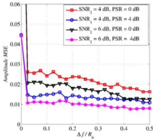
Fig. 1 presents the amplitude MSE as a function of the relative frequency shift ∆f /Rb2. The proposed estimator offers good performance for values of ∆f /Rb higher than 0.025. For values of ∆f /Rb smaller than 0.025, the time average of the coefficients ρ(1),(2)(u, u) and ρ(1),(2)(u, u − 1) are not negligi-ble and the approximation in (8) does not hold. Subsequently, we assume that ∆f /Rb≥ 0.025.
Fig. 1. Amplitude MSE for the signal with the highest power r(1)(t) as a function of ∆f /Rbfor L = 40 and δf(1)/Rb= 1.10−3.
Fig. 2 presents the amplitude MSE as a function of both the WA length L and the relative frequency offset δf(1)/Rb. An optimal length Lopt minimizing the MSE of the amplitude estimator exists for each value of δf(1)/Rb. In particular, the optimal length Lopt is equal to 32 for δf(1)/Rb = 3.10−3, and 85 for δf(1)/Rb = 1.10−3. When δf(1)/Rb = 0, the MSE for the amplitude estimator decreases monotonically with the length of the window. Now, we compare the MSE of the amplitude estimator with the MCRB. We use the MCRB because analytical expressions of this bound are available. The results show that the performance of the amplitude estimator approaches the MCRB (see Fig. 3 and Fig. 4). However, 1The bandwidth is 110 kHz, the spectral analysis performed by the ARGOS receiver uses a 8192-point FFT, and Rb= 400 bits/s.
2The relative frequency shifts are limited to [0,4] since the power of a bi-phase signal is concentrated in the [−4Rb, 4Rb] band.
Fig. 2. Amplitude MSE for the signal with the highest power r(1)(t) as a function of the window length L for SN R1 = 8 dB, P SR = 0 dB, and ∆f /Rb= 0.75.
Fig. 3. Amplitude MSE for the signal with the highest power r(1)(t) as a function of SN R1for L = 50, P SR = 4 dB, and ∆f /Rb= 0.75.
Fig. 4. Amplitude MSE for the signal with the lowest power r(2)(t) as a function of SN R2for L = 50, P SR = 4 dB, and ∆f /Rb= 0.75.
it is also shown that the amplitude estimator is biased for
δf(1)/Rb 6= 0. Further studies should provide a means to remove this bias.
B. Performance of the Carrier Phase Estimator
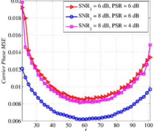
The carrier phase estimate ˆθ(1) is unwrapped after the esti-mation procedure [14], so that the resulting phase ˘θ(1) is in [−π, π]. A phase ambiguity of ±2π occurs but this ambiguity is not critical since it does not affect the symbol decision. Similarly to amplitude estimation, Fig. 5 presents the effects of the WA length L and the relative frequency offset δf(1)/R
b on the carrier phase MSE. The results show the existence of an optimal length Lopt for a given value of the relative frequency offset. However, we note that this optimal length is twice the one obtained for the amplitude estimator. For example, for a δf(1)/Rb of 3.10−3, the optimal length to minimize the amplitude MSE is 32, however it is of 63 to minimize the carrier phase MSE. This result comes from the fact that the
Fig. 5. Carrier phase MSE for the signal with the highest power r(1)(t) as a function of the window length L for δf(1)/R
b= 3.10−3and ∆f /Rb= 0.25
signal amplitude is estimated once for all the window of length L. The presence of a relative frequency offset δf(1)/R
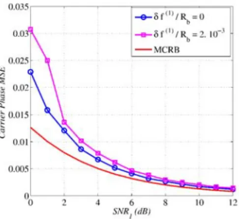
baffects each sample m of the window with the value (δf(1)m)/Rb. Thus, the maximum offset value is (δf(1)L)/Rbat the edge of the window. However, for the phase estimation, the estimates holds for the sample in the middle of the window. This sample is affected by a maximum offset value of (δf(1)L)/2Rb. This explains our results. Finally, the MSE of the carrier phase estimator is compared to the MCRB. The results are shown in Fig. 6 and Fig. 7. The results show that the performance of the phase estimator approaches also the MCRB values. Thus, the Viterbi & Viterbi estimator can be used for carrier phase estimation in the ARGOS system.
The optimal length Lopt is not the same when considering the amplitude estimator or the carrier phase estimator. So another approach is needed to choose the most appropriate window length L. When L is in the interval [30 40], the amplitude MSE is lower than 0.01 and the carrier phase MSE is lower than 0.012, for any value of the relative frequency offset δf(1)/Rb. An MSE value of 0.01 for the amplitude estimator has been
Fig. 6. Carrier phase MSE for the signal with the highest power r(1)(t) as a function of SN R1 for L = 51, P SR = 4 dB, and ∆f /Rb= 0.75.
Fig. 7. Carrier phase MSE for the signal with the lowest power r(2)(t) as a function of SN R2 for L = 51, P SR = 0 dB, and ∆f /Rb= 0.875.
shown to induce an additional loss on the received SNR that is lower than 0.05 dB, i.e., the received SNR is degraded by a factor lower than 0.05 dB when the MSE of the amplitude estimator is lower than 0.01 [4]. Similarly, an MSE value of 0.012 for the carrier phase estimator induces an additional loss on the received SNR that is lower than 0.05 dB [15]. These SNR losses are much lower than the ones induced by imperfect time delay estimation [4].
V. CONCLUSION
In this paper, we propose an NDA feed forward estimator for the ARGOS system. The proposed estimator is based on the Viterbi & Viterbi algorithm. This algorithm has been originally designed for a single user scenario, and it has been adapted here to the multi-user case of the ARGOS system. The proposed algorithm estimates the amplitude as well as the carrier phase of each user, in the presence of a frequency offset. A GWA is used to obtain unbiased estimates of the symbols. The estimator uses a WA to reduce the influence of the additive noise. However, in the presence of
a given frequency offset, increasing the WA length reduces also the useful component, so an optimal length Lopt should be determined. Because the two estimators provide different Lopt, a trade-off is made: the window length is chosen in the interval [30 40] so that MSEs on both estimators are lower than 0.012 and the induced degradation on the received SNR is lower than 0.05 dB. Simulation results have been obtained assuming perfect estimation of the time delays. The results show that the performance of the estimator in terms of MSE approaches the MCRB. Thus, the Viterbi & Viterbi estimator can be implemented for both amplitude and carrier phase estimation for the ARGOS system.
Time delay and carrier frequency estimators should now be considered in order to complete this study. This step is critical since it should ensure the good operation of the estimator proposed in this paper. In particular, the carrier frequency estimator should ensure that frequency errors are in the range of the frequency offset values given in this paper. This part is left for future work.
REFERENCES
[1] “Argos: Worldwide tracking and environmental monitoring by satellite,” http://www.argos-system.org.
[2] CNES, “Platform Transmitter Terminal (PTT-A2) Platform Message Transceiver (PMT-A2) - Physical Layer System Requirements,” in AS3-SP-516-274-CNES, 2006.
[3] F. Fares, M.L. Boucheret, B. Escrig, T. Calmettes, and H. Guillon, “Multiuser Detection for Asynchronous ARGOS Signals,” in IEEE, IET International Symposium on Communication Systems, Networks and Digital signal Processing (CSNDSP), July 2010.
[4] B. Escrig, F. Fares, M.L. Boucheret, T. Calmettes, and H. Guillon, “Impact of Imperfect Parameter Estimation on the Performance of Multi-User ARGOS Receivers,” in IEEE Global Communications (Globecom), Dec. 2010.
[5] K. Moon and X. Zhenhua, “Parameter Estimation in a Multi User Communication System,” in IEEE Transactions on Communication, Vol. 42, pp. 2553-2560, 1994.
[6] X. Zhenhua, K. Rushforth, T. Short, and K. Moon, “Joint Signal Detection and Parameter Estimation in Multiuser Communications,” in IEEE Transactions on Communications, Vol. 41, pp. 1208-1216, 1993. [7] F. Daffara and J. Lamour, “Comparison Between Digital Phase Recovery Techniques in the Presence of a Frequency Shift,” Vol. 2, pp. 940-945, 1994.
[8] A.J. Viterbi and A.M.Viterbi, “Nonlinear Estimation of PSK-Modulated Carrier Phase with Applications to Burst Digital Transmission,” in IEEE Transactions on Information Theory, Vol. IT 29, pp. 543-551, 1983. [9] G. Jonghe and M. Moeneclaey, “Optimal Averaging Filter Length of the
Viterbi & Viterbi Carrier Synchronizer for a Given Frequency Offset,” Communication Enginering Lab, 1994.
[10] J.P Delmas, “Closed Form Expressions of the Exact Cramer Rao Bound for Parameter Estimation of BPSK, MSK, or QPSK Waveforms,” in IEEE Signal Processing Letters, Vol. 15, pp. 405-408, 2008.
[11] A. D. Andrea, U. Mengali, and R. Reggiannini, “The Modified Cramer Rao Bound and Its Application to Synchronization Problems,” in IEEE Transactions on Communications, Vol. 42, pp. 1391-1399, 1994. [12] G. Jonghe and M. Moeneclaey, “The Effect of the Averaging Filter on
the Cycle Slipping of NDA Feed Forward Carrier Synchronizers for MPSK,” Communication Enginering Lab, 1992.
[13] B. Paden, “A Matched Non Linearity for Phase Estimation of a PSK Modulated Carrier,” in IEEE Transactions on Information Theory, Vol. 3, May 1986 .
[14] M. Fitz, “Equivocation in Nonlinear Digital Carrier Synchronizers,” in IEEE Transactions on Communications, Vol. 39, 1991.
[15] F. Fares, Traitement des signaux ARGOS 4, Ph.D., Universit´e de Toulouse, INPT, Toulouse, France (in French), 2010 [Online]. Available: http://ethesis.inp-toulouse.fr/archive/00001533/01/fares.pdf