Pépite | Identification des mécanismes d’impact des interférences électromagnétiques sur des communications Wi-Fi
115
0
0
Texte intégral
(2) Thèse de Grecia Romero, Lille 1, 2017. © 2017 Tous droits réservés.. lilliad.univ-lille.fr.
(3) Thèse de Grecia Romero, Lille 1, 2017. Acknowledgment. I thank all who in one way or another contributed to the completion of this thesis. First, I thank God for giving me courage, strength and confidence to achieve this goal. I would like to express my sincere gratitude to my advisor Dr. Virginie DENIAU, for her support of my Ph.D study and related research, for her patience, motivation, and immense knowledge. Her guidance helped me in all the time of research and writing of this thesis. I would like to offer my special thanks to Prof. Eric SIMON for accepting me as his PhD student and for giving me the opportunity to pursue my PhD, thanks for these three years. Thanks to professor Martine LIENARD for giving me access to the laboratory and research facilities. I would like to extend my gratitude to all the members of the Telice group for their cordiality, and also thanks to Christophe GRANSART for his helpful comments. I am particularly grateful to my jury committee Prof. Daniel ROVIRAS, Dr. Guillaume FERRE, Prof. Maryline HELARD, Prof. Charly POULLIAT and Dr. Gemma MORRAL, for their insightful comments and encouragement. I would also like to acknowledge with much appreciation the crucial role of my angels William, Rosmilar and Julio, without their precious support, I could have never done this without you. Thank you for having faith in me and always encouraging me to continue pursuing my goals. I will be immensely grateful to you all my life.. 3. © 2017 Tous droits réservés.. lilliad.univ-lille.fr.
(4) Thèse de Grecia Romero, Lille 1, 2017. 4 I express my heartfelt gratitude to my lifelong friends: Yuli, Asdrubal, Carlos, Eliecer, Henry, Hilario, Elimar, Ulises, Capi and Ataya. In spite of the distance our friendship remains strong. I consider myself the luckiest person in the world to have such supportive friends, standing behind me with their love and support. I am particular grateful to my colleagues and friends at the telecommunication Department of University of Carabobo in Venezuela, in particular, Prof. Del Pino, Prof. Fedon, Prof. Benjamin, Prof. Albornoz, Mejias, Cesar, Eduardo, Ahmad, Henry and all the teachers from who I learnt since my engineering studies and without their guidance, I would not have been here, blessing and support. A special gratitude to my friends in France, Benjamin, Carina, Gwen, Madeleine, Navish, Ludo, Floreal, Stefanie, Jef, Cedric, Guillaume, Bernard, Adeline, Celine, Elise, Tony, my Remis, yoga and runcrew59 friends, for being present during these last three years in the good and bad times of my life. Your suggestions and encouragement helped me integrate into French life. Thanks for supporting me spiritually throughout the writing process of this thesis and my life in general. Last but not the least, I would like to thank my family, especially my mother for her love, support, and constant encouragement I have gotten over the years. Thank you for making me who I am.. © 2017 Tous droits réservés.. lilliad.univ-lille.fr.
(5) Thèse de Grecia Romero, Lille 1, 2017. Résumé. Le développement des communications sans fil a causé la surcharge des bandes de fréquences utilisables. Afin de poursuivre ce développement, les nouveaux systèmes sans fil doivent utiliser efficacement le spectre sans interférer avec les autres systèmes. Ainsi, ces nouveaux systèmes sans fil doivent être capables de détecter l’environnement électromagnétique (EM) afin d’être configurés de manière optimale et de devenir robustes dans cet environnement. Pour accomplir une configuration optimale face aux environnements EM, il est impératif de comprendre comment ces environnements EM affectent les systèmes de communication. Dans cette thèse, nous nous sommes particulièrement intéressés au secteur des transports, notamment les trains à grande vitesse. Dans ce secteur, on peut trouver des interférences EM intentionnelles (IEMI) et des interférences EM non intentionnelles (EMI). Cette thèse porte sur les deux types d’interférences. Nous avons considéré comme interférences électromagnétiques non intentionnelles (EMI) les signaux d’interférences électromagnétiques transitoires produites par les pertes de contact entre la caténaire et le pantographe. Ces interférences sont très présentes sur les trains à grande vitesse. Pour les interférences EM intentionnelles (IEMI), nous avons utilisé des signaux d’interférence générés par des brouilleurs faible puissance que l’on trouve dans le commerce. Nous avons choisi la norme IEEE 802.11n comme système de communication en raison de son développement actuel dans le secteur des transports. Afin d’étudier la vulnérabilité du réseau de communication IEEE 802.11n face à ces différents types d’interférences, nous avons effectué différentes expériences en chambre anéchoïque puis avons interprété les résultats de ces expériences.. 5. © 2017 Tous droits réservés.. lilliad.univ-lille.fr.
(6) Thèse de Grecia Romero, Lille 1, 2017. 6 Nous avons alors identifié le mécanisme d’accès au canal comme un point potentiellement vulnérable aux deux types d’interférences. En effet une interférence de faible puissance pourrait faire croire que le canal est occupé, empechant toute communication. Concernant les IEMI, nous avons de plus remarqué que la période de balayage (SP) de la bande de fréquence du signal de brouillage est un paramètre important pour l’efficacité du brouillage. La période de balayage la plus nuisible était à 20 µs, car le brouillage couvre alors tout le canal. Pour les signaux d’interférences EM transitoires, nous avons identifié la période DCF Interframe Space (DIFS) comme un autre paramètre vulnérable de la norme, car à partir d’un certain niveau de puissance d’interférence et dès que l’intervalle de répétition entre les transitoires (T) est inférieur à 24 µs, la communication est systématiquement interrompue. Ce chiffre est à mettre en relation avec la période DIFS.. © 2017 Tous droits réservés.. lilliad.univ-lille.fr.
(7) Thèse de Grecia Romero, Lille 1, 2017. Abstract. The increase in the wireless communication development has overloaded the usable frequency bands. In order to continue with this development, new wireless systems must use the spectrum more efficiently to avoid interference with other systems. Thus, these new wireless systems must be capable of sensing EM environment in order to be configured optimally and to become robust in this environment. To accomplish an optimal configuration considering the EM environment, it is imperative to understand these EM environments affect communication systems. In this thesis, we are particularly interested in the transportation sector, especially in high speed trains. In this sector both unintentional EM interferences (EMI) and intentional EM interferences (IEMI) can be found. This thesis is focused on both interference types. We considered unintentional EM interferences (EMI), such as transient EM interference signals produced by contact losses between the catenary and the pantograph. These interference are present on high speed trains. For intentional EM interferences (IEMI) we used interference signals as those generated by low power commercial jammers. We have chosen the IEEE 802.11n standard as the communication system due to the fact that the current developments in the transportation sector is based on the Wi-Fi technology. In order to study the vulnerability of the IEEE 802.11n communication network facing these different interference types, we carried out different experiments in a semi-anechoic chamber and then we interpreted the results of these experiments. We identified the channel access mechanism as a vulnerable feature of IEEE 802.11n. As a mater of fact, in the presence of a low power interference, the channel can be con7. © 2017 Tous droits réservés.. lilliad.univ-lille.fr.
(8) Thèse de Grecia Romero, Lille 1, 2017. 8 sidered busy by the channel access mechanism, preventing any communication. With regard to the IEMI, we have noticed that the sweep period (SP) of the frequency band of the jamming signal is an important parameter on the jamming performance. The most harmful sweep period was to 20 µs, because the jamming covers the whole channel. For transient EM interference signals, we identified the DCF Interframe Space (DIFS) period as another vulnerable parameter of the standard. Because when the repetition interval between transients (T) is lower than 24 µs, with a certain interference power level, the communication is systematically interrupted. This figure is of the same order of magnitude as the DIFS period.. © 2017 Tous droits réservés.. lilliad.univ-lille.fr.
(9) Thèse de Grecia Romero, Lille 1, 2017. Contents. List of figures. 13. List of tables. 17. List of acronyms and variables. 19. Introduction. 23. 1 IEEE 802.11n standard 1.1 IEEE 802.11 . . . . . . . . . . . . . . . . . . . . . . 1.2 IEEE 802.11n standard . . . . . . . . . . . . . . . . 1.3 PHY Layer Characteristics . . . . . . . . . . . . . . 1.3.1 Orthogonal Frequency Division Multiplexing 1.3.2 Modulation Coding Scheme (MCS) index . . 1.3.3 Rate adaptation algorithms . . . . . . . . . 1.4 MAC Layer Characteristics . . . . . . . . . . . . . . 1.4.1 Distributed Coordination Function (DCF) . 1.4.2 The backoff procedure . . . . . . . . . . . . 1.4.3 Inter Frame Space (IFS) . . . . . . . . . . . 1.4.4 CSMA/CA with RTS/CTS . . . . . . . . . 1.5 Carrier sense (CS) mechanisms . . . . . . . . . . . 1.5.1 Physical carrier sense . . . . . . . . . . . . 1.6 Analysis of the frame types used by IEEE 802.11 . 1.7 802.11 MAC Frame Format . . . . . . . . . . . . .. 27 28 30 31 31 33 35 35 36 36 37 40 40 41 42 42. . . . . . . . . . . . . . . . . . . (OFDM) . . . . . . . . . . . . . . . . . . . . . . . . . . . . . . . . . . . . . . . . . . . . . . . . . . . . . . . . . . . . . . . . . .. . . . . . . . . . . . . . . .. . . . . . . . . . . . . . . .. . . . . . . . . . . . . . . .. . . . . . . . . . . . . . . .. . . . . . . . . . . . . . . .. . . . . . . . . . . . . . . .. 9. © 2017 Tous droits réservés.. lilliad.univ-lille.fr.
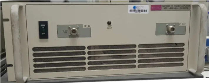
(10) Thèse de Grecia Romero, Lille 1, 2017. 10. CONTENTS. 1.8 1.9. 1.7.1 Data frame . . . . . . 1.7.2 Control frame . . . . . 1.7.3 Management frames . IEEE 802.11n communication Conclusion . . . . . . . . . . .. . . . . .. . . . . .. . . . . .. . . . . .. . . . . .. . . . . .. . . . . .. . . . . .. . . . . .. . . . . .. . . . . .. . . . . .. . . . . .. . . . . .. . . . . .. . . . . .. . . . . .. . . . . .. . . . . .. . . . . .. . . . . .. . . . . .. . . . . .. . . . . .. 43 44 45 46 50. 2 Electromagnetic interference 51 2.1 Unintentional electromagnetic interference . . . . . . . . . . . . . . . . . 52 2.1.1 Introduction to the different kind of emissions in the transport system . . . . . . . . . . . . . . . . . . . . . . . . . . . . . . . . . 52 2.1.2 Characteristics of the EM interferences produced by contact losses between the catenary and the pantograph . . . . . . . . . . . . . 56 2.1.3 Mathematical model of EM interference produced by contact losses between the catenary and the pantograph . . . . . . . . . . . . . 58 2.2 Intentional electromagnetic interference . . . . . . . . . . . . . . . . . . 60 2.2.1 Classification of jamming . . . . . . . . . . . . . . . . . . . . . . . 61 2.2.2 Analysis of conventional jammers . . . . . . . . . . . . . . . . . . 62 2.2.3 Mathematical model of the frequency sweeping jamming . . . . . 67 3 Measurements and interpretations 3.1 Experimental approach . . . . . . . . . . . . . . . . . . . 3.1.1 Testing tools . . . . . . . . . . . . . . . . . . . . 3.1.1.1 Iperf . . . . . . . . . . . . . . . . . . . . 3.1.1.2 Wireshark . . . . . . . . . . . . . . . . . 3.1.2 Measurement equipment . . . . . . . . . . . . . . 3.1.2.1 Tektronix AWG7102 Signal Generator . 3.1.2.2 LeCroy WaveMaster 813Zi Oscilloscope . 3.1.2.3 J7211A Attenuation Control Unit . . . . 3.1.2.4 GRF5060 RF Power Amplifier . . . . . . 3.1.2.5 Antennas . . . . . . . . . . . . . . . . . 3.1.3 Experimental setup . . . . . . . . . . . . . . . . 3.1.3.1 Equipment setup . . . . . . . . . . . . . 3.1.3.2 Measurement Setup . . . . . . . . . . . 3.2 Frequency sweeping jamming . . . . . . . . . . . . . . . 3.2.1 Signal Parameters . . . . . . . . . . . . . . . . . . 3.2.1.1 Interference to signal power ratio (ISR) 3.2.1.2 Sweep Period (SP) . . . . . . . . . . . .. © 2017 Tous droits réservés.. . . . . . . . . . . . . . . . . .. . . . . . . . . . . . . . . . . .. . . . . . . . . . . . . . . . . .. . . . . . . . . . . . . . . . . .. . . . . . . . . . . . . . . . . .. . . . . . . . . . . . . . . . . .. . . . . . . . . . . . . . . . . .. . . . . . . . . . . . . . . . . .. . . . . . . . . . . . . . . . . .. 69 70 70 70 71 71 71 72 72 73 73 74 74 76 77 77 78 78. lilliad.univ-lille.fr.
(11) Thèse de Grecia Romero, Lille 1, 2017. CONTENTS 3.2.2 3.2.3 3.2.4. 3.3. Experimental setup . . . . . . . . . . . . . . . . . Measurement results . . . . . . . . . . . . . . . . Interpretation of the measurements . . . . . . . . 3.2.4.1 Observations based on the spectrum . . 3.2.4.2 Observations based on the CCA . . . . . 3.2.5 Conclusions on frequency sweeping jamming . . . Transient EM interferences . . . . . . . . . . . . . . . . . 3.3.1 Signal Parameters . . . . . . . . . . . . . . . . . . 3.3.1.1 Repetition period (T) . . . . . . . . . . 3.3.1.2 Interference to signal power ratio (ISR) 3.3.2 Experimental setup . . . . . . . . . . . . . . . . . 3.3.3 Measurement results . . . . . . . . . . . . . . . . 3.3.4 Interpretation of the measurements . . . . . . . . 3.3.5 Conclusion on the transient EM interferences . . .. 11 . . . . . . . . . . . . . .. . . . . . . . . . . . . . .. . . . . . . . . . . . . . .. . . . . . . . . . . . . . .. . . . . . . . . . . . . . .. . . . . . . . . . . . . . .. . . . . . . . . . . . . . .. . . . . . . . . . . . . . .. . 78 . 80 . 82 . 82 . 89 . 93 . 94 . 94 . 94 . 95 . 95 . 97 . 103 . 105. General conclusion and perspectives. 107. Bibliography. 111. © 2017 Tous droits réservés.. lilliad.univ-lille.fr.
(12) Thèse de Grecia Romero, Lille 1, 2017. © 2017 Tous droits réservés.. lilliad.univ-lille.fr.
(13) Thèse de Grecia Romero, Lille 1, 2017. List of Figures. 1.1 1.2. OSI model. . . . . . . . . . . . . . . . . . . . . . . . . . . . . . . . . . . Representation of OFDM subcarriers with a frequency spacing (∆f ) of 312.5 kHz. . . . . . . . . . . . . . . . . . . . . . . . . . . . . . . . . . . . 1.3 Some IFS relationships [Sta12, p.826.] . . . . . . . . . . . . . . . . . . . . 1.4 RTS/CTS/data/ACK settings [Sta12]. . . . . . . . . . . . . . . . . . . . 1.5 IEEE 802.11 Frame format. . . . . . . . . . . . . . . . . . . . . . . . . . 1.6 RTS frame [Sta12]. . . . . . . . . . . . . . . . . . . . . . . . . . . . . . . 1.7 CTS frame [Sta12]. . . . . . . . . . . . . . . . . . . . . . . . . . . . . . . 1.8 ACK frame [Sta12]. . . . . . . . . . . . . . . . . . . . . . . . . . . . . . . 1.9 Connection scheme between a client and a server connected through an AP. 1.10 Representations of an IEEE 802.11n communication between AP and client. 1.11 Time domain and Time-Frequency representations of an IEEE 802.11n communication between AP and client by oscilloscope. . . . . . . . . . . 1.12 Time-Frequency representation of an IEEE 802.11n communication between AP and client by real-time spectrum analyzer. . . . . . . . . . . . 2.1 2.2 2.3 2.4 2.5 2.6. Road freight transport powered by electricity [Sie17]. . . . . . . . . . . . APS system by Alstom [Als17]. . . . . . . . . . . . . . . . . . . . . . . . SRS system by Alstom [Als17]. . . . . . . . . . . . . . . . . . . . . . . . Elways system [Elw17] . . . . . . . . . . . . . . . . . . . . . . . . . . . . Interference signals measured in the railway environment; (a) Time domain representation, (b) Time-Frequency representation. . . . . . . . . . The double exponential signal represented in time domain and frequency domain, applying a 40 ns window. . . . . . . . . . . . . . . . . . . . . . .. 28 32 39 41 42 44 45 45 47 48 49 49 53 54 54 55 57 59. 13. © 2017 Tous droits réservés.. lilliad.univ-lille.fr.
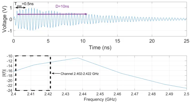
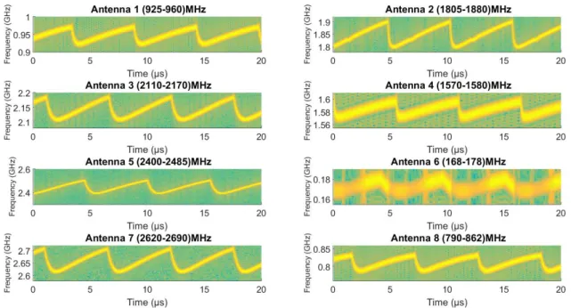
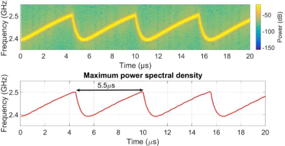
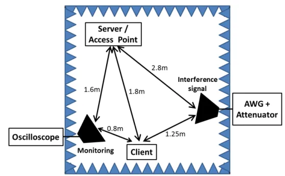
(14) Thèse de Grecia Romero, Lille 1, 2017. 14. LIST OF FIGURES 2.7. 2.8 2.9 2.10 2.11 2.12 2.13 2.14 3.1 3.2 3.3 3.4 3.5 3.6 3.7 3.8 3.9 3.10 3.11 3.12 3.13. © 2017 Tous droits réservés.. Time and frequency representations of a double exponential signal with D=10 ns, Trise = 0.5 ns and T = 10 µs. The frequency representation is obtained with a 20 µs time window. . . . . . . . . . . . . . . . . . . . . . Experimental setup; (a) with spectrum analyser, (b) with oscilloscope. . . Spectrum representation of each output of the commercial jammer (Table 2.1). . . . . . . . . . . . . . . . . . . . . . . . . . . . . . . . . . . . . . . Time-Frequency representation of each output of the commercial jammer (Table 2.1). . . . . . . . . . . . . . . . . . . . . . . . . . . . . . . . . . . Spectrogram of the antenna 5 of the commercial jammer (Table 2.1). . . Spectrum representation of the antenna 5 of the commercial jammer (Table 2.1). . . . . . . . . . . . . . . . . . . . . . . . . . . . . . . . . . . . . Time-Frequency representation of the frequency sweeping interference signal. . . . . . . . . . . . . . . . . . . . . . . . . . . . . . . . . . . . . . . . The frequency sweeping interference signal with a sweep period of 10 µs in the time domain and Time-Frequency representations. . . . . . . . . . Tektronix AWG7102 Signal Generator. . . . . . . . . . . . . . . . . . . . LeCroy Wave Master 813Zi Oscilloscope. . . . . . . . . . . . . . . . . . . J7211A Attenuation Control Unit. . . . . . . . . . . . . . . . . . . . . . . GRF5060 RF Power Amplifier. . . . . . . . . . . . . . . . . . . . . . . . Types of antennas used; (a) Double ridge guide horn antenna, (b) EM6116 omnidirectional antenna. . . . . . . . . . . . . . . . . . . . . . . . . The general scheme of the experimental setup, including the monitoring system, the interference system, and the IEEE 802.11n test network. . . . The scheme of the experimental setup, including: the monitoring system, the interference system, and the test network. . . . . . . . . . . . . . . . Experimental setup in the semi-anechoic chamber. . . . . . . . . . . . . . Location diagram of the equipment inside the semi-anechoic chamber. . . Bit Rate measurements, as a function of the ISR. . . . . . . . . . . . . . Required value of the ISR to completely interrupt the communication, as a function of the SP. . . . . . . . . . . . . . . . . . . . . . . . . . . . . . Bit Rate measurements, as a function of the ISR for SP = 0.64, 1.06, 1.6 and 5.5 µs. . . . . . . . . . . . . . . . . . . . . . . . . . . . . . . . . . . Spectra of the frequency sweeping interference signals obtained by FFT over a 3.2 µs window, for SP = 0.64, 1.06, 1.6 and 5.5 µs, between 2.4 GHz and 2.45 GHz. . . . . . . . . . . . . . . . . . . . . . . . . . . . . . .. 60 63 64 64 66 66 68 68 72 72 73 73 74 75 79 79 80 81 82 83. 84. lilliad.univ-lille.fr.
(15) Thèse de Grecia Romero, Lille 1, 2017. LIST OF FIGURES 3.14 Bit Rate measurements, as a function of the ISR for SP = 20, 30, 40 and 50µs. . . . . . . . . . . . . . . . . . . . . . . . . . . . . . . . . . . . . . . 3.15 Spectra of the frequency sweeping signals obtained by FFT over a 3.2 µs window, for SP = 20, 30, 40 and 50µs. . . . . . . . . . . . . . . . . . . . 3.16 Bit Rate measurements, as a function of the ISR for SP = 6.4, 10, 20 and 30 µs. . . . . . . . . . . . . . . . . . . . . . . . . . . . . . . . . . . . . . 3.17 Spectra of the frequency sweeping signals obtained by FFT over a 3.2 µs window, for SP = 6.4, 10, 20 and 30 µs. . . . . . . . . . . . . . . . . . . 3.18 Illustration of the STFT processing. . . . . . . . . . . . . . . . . . . . . . 3.19 Highest average power over the 20 MHz communication channel for different sweep periods. . . . . . . . . . . . . . . . . . . . . . . . . . . . . . 3.20 Illustration of the relationship between the sweep period and the signal processing time window used for average power measurement at the reception. . . . . . . . . . . . . . . . . . . . . . . . . . . . . . . . . . . . . 3.21 The scheme of the experimental setup, including: the monitoring system, the interference system, and the test network. . . . . . . . . . . . . . . . 3.22 Experimental setup in the semi-anechoic chamber. . . . . . . . . . . . . . 3.23 Location diagram of the equipment inside the semi-anechoic chamber. . . 3.24 Bit Rate measurements, as a function of the T for A = 1 V. . . . . . . . 3.25 Bit Rate measurements, as a function of the T for A = 1 V and 10 V. . . 3.26 Bit Rate measurements, as a function of ISR for A = 1 V and T= 27 µs, 25 µs and 24 µs. . . . . . . . . . . . . . . . . . . . . . . . . . . . . . . . 3.27 Bit Rate measurements, as a function of the attenuation levels, for A = 1 V and different T values. . . . . . . . . . . . . . . . . . . . . . . . . . 3.28 Bit Rate measurements, as a function of the ISR for A = 1 V and different T values. . . . . . . . . . . . . . . . . . . . . . . . . . . . . . . . . . . . . 3.29 Attenuation value required to completely interrupt the communication, as a function of the T . . . . . . . . . . . . . . . . . . . . . . . . . . . . . 3.30 ISR value required to completely interrupt the communication, as a function of the T . . . . . . . . . . . . . . . . . . . . . . . . . . . . . . . . . . 3.31 Bit Rate measurements, as a function of ISR for A = 1 V and T= 27 µs and 25 µs. . . . . . . . . . . . . . . . . . . . . . . . . . . . . . . . . . . . 3.32 Example of capturing packets with Wiresharkof traffic flow over the network in the presence of a interference signal. . . . . . . . . . . . . . . . .. © 2017 Tous droits réservés.. 15. 86 87 88 89 91 92. 93 96 96 97 98 99 100 101 101 102 102 104 105. lilliad.univ-lille.fr.
(16) Thèse de Grecia Romero, Lille 1, 2017. © 2017 Tous droits réservés.. lilliad.univ-lille.fr.
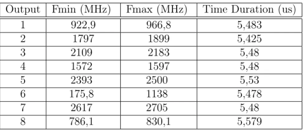
(17) Thèse de Grecia Romero, Lille 1, 2017. List of Tables. 1.1 1.2 1.3 2.1 2.2. PHY layer specifications of the IEEE 802.11n standards [Sta12]. . . . . Modulation and coding schemes in single stream for IEEE 802.11n [Sta12, pp.1771-1780]. . . . . . . . . . . . . . . . . . . . . . . . . . . . . . . . . . Values of some parameters in DFC of IEEE 802.11n [Sta12, p.1761] . . . Jammer characteristics. . . . . . . . . . . . . . . . . . . . . . . . . . . . . Spectrogram measurement results of the commercial jammer with 8 output port . . . . . . . . . . . . . . . . . . . . . . . . . . . . . . . . . . . .. 32 34 39 62 65. 17. © 2017 Tous droits réservés.. lilliad.univ-lille.fr.
(18) Thèse de Grecia Romero, Lille 1, 2017. © 2017 Tous droits réservés.. lilliad.univ-lille.fr.
(19) Thèse de Grecia Romero, Lille 1, 2017. List of acronyms and variables. 19. List of acronyms. ACK AP APS ARF AWG BCC BPSK CCA CCA-ED CCK CRC CS CS/CCA CSMA/CA CTS CW DCF DFT DSSS DIFS EIFS EM EMC EMI EQM FC FCS FEC. © 2017 Tous droits réservés.. Acknowledgment Access Point Alimentation Par le Sol Auto Rate Fallback Arbitrary Waveform Generator Binary Convolutional Code Binary Phase Shift Keying Clear Channel Assessment Clear Channel Assessment-Energy Detect Complementary Code Keying Cyclic Redundancy Check Carrier Sense Carrier Sense/Clear Channel Assessment Carrier Sense Multiple Access with Collision Avoidance ll Clear To Send Contention Window Distributed Coordination Function Discrete Fourier Transform Direct Sequence Spread Spectrum Distributed Interframe Space Extended Interframe Space Electromagnetic Electromagnetic Compatibility Unintentional Electromagnetic Interference Equal Modulation Frame Control Frame Check Sequence Forward Error Correction. lilliad.univ-lille.fr.
(20) Thèse de Grecia Romero, Lille 1, 2017. 20. List of acronyms and variables FFT GI IEEE IEMI IFS ISI ISM LDPC NAV MAC MCS MIMO OFDM OSI PHY PLCP PMD QAM QPSK RIFS RBAR RSSI RTS SDM SIFS SNR ST STBC STFT SRS TCP UEQM UDP WECA Wi-Fi WLAN. © 2017 Tous droits réservés.. Fast Fourier Transform Guard Interval Institute of Electrical and Electronics Engineers Intentional Electromagnetic Interference Inter Frame Space Inter Symbol Interference Industrial Scientific and Medial Low-Density Parity-Check Network Allocation Vector Media Access Control Modulation and Coding Scheme Multiple Input Multiple Output Orthogonal Frequency Division Multiplexing Open System Interconnection Physical Physical Layer Convergence Procedure Physical Medium Dependant Quadrature Amplitude Modulation ll Quadrature Phase Shift Key Reduced Inter Frame Space Receiver Based Auto Rate Received Signal Strength Indicator Request to Send Spatial Division Multiplexing Short Interframe space Signal to Noise Ratio Slot Time Space-Time Block Coding Short Time Fourier Transform Systeme de Recharge Statique Transmission Control Protocol Unequal Modulation User Datagram Protocol Wireless Ethernet Compatibility Alliance Wireless Fidelity Wireless Local Area Network. lilliad.univ-lille.fr.
(21) Thèse de Grecia Romero, Lille 1, 2017. List of acronyms and variables. 21. List of variables ∆f A D fs f0 i(t) ISR PI PS SP T Trise Tu. © 2017 Tous droits réservés.. Subcarrier spacing Interference signal amplitude Time duration Sampling rate Center frequency of Wi-Fi channel ll Interference signal Interference to Signal Power Ratio Interference signal power IEEE 802.11n communication signal power Sweep period or time duration to scan the frequency band of interest Repetition interval between successive transients Rise time Duration of the useful part of the OFDM symbol. lilliad.univ-lille.fr.
(22) Thèse de Grecia Romero, Lille 1, 2017. © 2017 Tous droits réservés.. lilliad.univ-lille.fr.
(23) Thèse de Grecia Romero, Lille 1, 2017. Introduction. These days, wireless communications are anywhere and become indispensable for people. By the broadcast nature of wireless communications, the electromagnetic (EM) spectrum must be shared by all forms of wireless communication, including WLAN, cellular telephones, radio and television broadcasting, GPS position locating, aeronautical and maritime radio navigation, and satellite command and control. The growth of these systems has caused the spectrum’s overload because the usable frequency bands are limited. Therefore, the spectrum must be used more efficiently in order that these wireless technologies coexist without interfering among them. Indeed, one possible solution is that these systems become intelligent, that means they may be able to sense the EM environment in order to be configured optimally and to be robust in this environment. To allow an optimal configuration, it is necessary to understand precisely the interference mechanisms on the communication systems. Therefore, we seek to comprehend how an interference signal affects a communication signal. In particular, we are interested in the transportation sector. This sector is rapidly evolving and the wireless communications are essential to optimize new transport services and to enhance the passenger experience. For instance, wireless communications offer the possibility of Internet connection on board transports, as well as to provide quick and updated information to the passengers about the journeys. Moreover, the transportation sector is innovating in order to reduce CO2 emissions by using renewable energies and to follow the ecological transition towards electric ve23. © 2017 Tous droits réservés.. lilliad.univ-lille.fr.
(24) Thèse de Grecia Romero, Lille 1, 2017. 24. Introduction. hicles. These electric vehicles comprise a set of electrical components (a high-voltage power source, a frequency converter, an electric motor and high-power cables) which constitutes new sources of EM interference (EMI) able to disturb wireless communications. Another significant evolution of the transportation sector is the intelligent autonomous transport systems. For instance, the ATO (Automatic Train Operation) is a device used to automate train operations. One of the challenges for this transportation system is the cybersecurity. Therefore, we must also take into account that the wireless systems have to be able to be resilient to cyber attacks. Among diverse cyber attacks, we are interested in communication jammers, which are intentional EM interference (IEMI) transmitters. Thus, this research work is focused on both the EMI and the IEMI, which can be found in the transportation sector, especially in high speed trains. To carry out this study, we consider a Wi-Fi communication network due to the current development of several applications in the automotive and railway sectors based on the Wi-Fi technology. For example, the solution studied to provide Internet on board trains is based on the deployment of Wi-Fi hot spot on board coaches. Can also be mentioned the IEEE 802.11p standard, which is a specific Wi-Fi version dedicated to automotive applications and which will permit the information transmission between cars. Thereby, the first chapter is dedicated to the description of the IEEE 802.11n which is the Wi-Fi version studied in this thesis. We will give an overview of this standard, introduce its main characteristics and highlight the key parameters which will be necessary to analyze the measurement results in chapter 3. Then, the second chapter presents the EM interferences which can be present in the transportation sector. They are classified as unintentional and intentional EM interferences. Among the unintentional EM interference (EMI), we focus on the transient EM interferences produced by contact losses between the catenary and the pantograph in high speed trains. Next, the intentional EM interferences (IEMI) are presented, including an analysis of a conventional jammer. In order to understand the impact of these intentional and unintentional EM interferences on an IEEE 802.11n communication network, this thesis will assess the communication performance under the presence of each interference type.. © 2017 Tous droits réservés.. lilliad.univ-lille.fr.
(25) Thèse de Grecia Romero, Lille 1, 2017. Introduction. 25. The third chapter gives the details of the whole experimental approach, including testing tools, measurement equipment and the general test setup used during the tests. This is followed by the description of each experiment carried out to evaluate the vulnerability of the IEEE 802.11n standard to the IEMI and the EMI. Different tests were carried out by varying the characteristics of the interference signals and identifying the relationship between the parameters of the interference signals and the communication performance degradation. Then, the measurement results and their interpretations will be presented, taking into account the impact of the signal processing performed at the receiver stage. Finally, we present our general conclusions and the perspectives of this work. Publications: The results of this research work have been published in IEEE Transactions on electromagnetic compatibility and in two conference publications URSI 2017. I received the Young Scientists Award for the paper [2]. Those are listed below: 1 Virginie Deniau, Christophe Gransart, Grecia L. Romero, Eric Pierre Simon, and Joumana Farah. "IEEE 802.11n Communications in the Presence of FrequencySweeping Interference Signals", IEEE Transactions on Electromagnetic Compatibility. Volume : 59. Issue: 5. 2017 2 Grecia Romero, Eric Pierre Simon, Virginie Deniau, Christophe Gransart and Mohamed Kousri. "Evaluation of an ieee 802.11n communication system in presence of transient electromagnetic interferences from the pantograph-catenary contact", 2017 URSI General Assembly and Scientific Symposium (GASS), august 19-26, 2017. 3 Mohamed Raouf Kousri, Virginie Deniau, Jean Rioult, Grecia Romero and Eric Simon. "Comparative study of transient disturbances impact on 2G and 4G telecommunication systems in a railway context", 2017 URSI General Assembly and Scientific Symposium (GASS), august 19-26, 2017.. © 2017 Tous droits réservés.. lilliad.univ-lille.fr.
(26) Thèse de Grecia Romero, Lille 1, 2017. © 2017 Tous droits réservés.. lilliad.univ-lille.fr.
(27) Thèse de Grecia Romero, Lille 1, 2017. Chapter. 1. IEEE 802.11n standard Nowadays, everyone wants to have Internet connection at all time, to access to their online services anywhere. In order to fulfill this expectation, Wi-Fi networks are deployed in different places, including transports (trains, buses, etc ) to offer Internet connection and service access. These new services permit to the passengers to optimize their travel time and feeling productive. Then, the quality of the Internet connection is important for the attractiveness and the image of public transports. However, the transport environment can be exposed to significant electromagnetic interferences. For this reason, Wi-Fi service should work well in different electromagnetic environments. In order to study the vulnerability of the IEEE 802.11 standard face to specific electromagnetic environments, the most determinant features of the Wi-Fi vulnerability have to be identified and their effect on the communication robustness in the presence of electromagnetic interferences has to be assessed. Indeed, this can permit to design future communication solutions more robust in specific electromagnetic environments. We chose the IEEE 802.11n standard which incorporates the most recent technology solutions, such as OFDM (Orthogonal Frequency Division Multiplexing) signals that can be used in the 5G communications for example in a filtered version. Moreover, IEEE 802.11n uses the 2.4 GHz band, which is the most common band in Wi-Fi communication systems nowadays. In this first chapter, the evolution of the IEEE 802.11 standard up to 802.11n is briefly described. We then focus on the main characteristics of the IEEE 802.11n stan27. © 2017 Tous droits réservés.. lilliad.univ-lille.fr.
(28) Thèse de Grecia Romero, Lille 1, 2017. © 2017 Tous droits réservés.. lilliad.univ-lille.fr.
(29) Thèse de Grecia Romero, Lille 1, 2017. CHAPTER 1. IEEE 802.11N STANDARD. 29. The Media Access Control (MAC) and Physical (PHY) layer specifications are covered by the IEEE 802.11 standard. This standard is developed by the Institute of Electrical and Electronics Engineers (IEEE) for Wireless Local Area Networks (WLANs). The first IEEE 802.11 standard was released in 1997 under the name of IEEE 802.11 with nominal data rates of 1 and 2 Mbps. Two years later, two amendments were added to the IEEE 802.11 standard:. • IEEE 802.11a-1999, known as 802.11a, enables raw data rates up to 54 Mbps in the Industrial Scientific and Medial (ISM) frequency band of 5 GHz using Orthogonal Frequency Division Multiplexing (OFDM) technology. • IEEE 802.11b-1999, known as 802.11b, is an extension of the original IEEE 802.11 specification by using Direct Sequence Spread Spectrum (DSSS) 1 technology . 802.11b employs the modulation technique known as Complementary Code Keying (CCK)2 that provides raw data rates up to 11 Mbps in the 2.4 GHz ISM band.. The 802.11b implementation was introduced on the market before the 802.11a [Cos10]. The 802.11b obtained a larger part of the market than 802.11a even reaching lower transmission rates. Indeed, the chips for the 2.4 GHz band were easier and cheaper to manufacture than the ones for the 5 GHz band. In 1999, a group of leading industry companies came together to form the Wireless Ethernet Compatibility Alliance(WECA), now known as Wi-Fi Alliance [Wi-17]. This group aims to facilitate a better interoperability, quality, and user experience for IEEE 802.11 devices from a broad range of vendors. The Wi-Fi Alliance adopted the term Wi-Fi - that means Wireless Fidelity - for products that satisfy interoperability certification testing. 1. DSSS is a spread spectrum modulation technique that is performed by multiplying the original data signal and a pseudo-noise (PN) digital signal. The result is in a wideband time continuous scrambled signal. 2 CCK is a modulation scheme similar to DSSS which uses a shorter chipping sequence in order to obtain higher data rate.. © 2017 Tous droits réservés.. lilliad.univ-lille.fr.
(30) Thèse de Grecia Romero, Lille 1, 2017. 30. 1.2. IEEE 802.11N STANDARD. Since then, the family of specifications developed by the IEEE for WLAN communications has had subsequent amendments with increasingly higher data rates. Each new amendment is incorporated in the latest version of the standard. The standard and the amendments provide the basis for wireless network products. We distinguish the particular specifications (e.g. 802.11a, 802.11b, 802.11g...) by the last letter. In 2009, the IEEE 802.11n [Sta12] was officially released. This amendment improved the previous 802.11 standards by adding Multiple Input Multiple Output (MIMO) technology. IEEE 802.11n employs Orthogonal Frequency Division Multiple (OFDM), operates on both 2.4 GHz and 5 GHz frequency bands and it allows wider channel bandwidths (40 MHz versus 20 MHz). As a result, 802.11n increased the theoretical data throughput from 54 Mbps to 300 Mbps in a 20 MHz channel, and 600 Mbps in a 40 MHz channel [Ins].. 1.2. IEEE 802.11n standard. IEEE 802.11n - Amendment 5: Enhancements for Higher Throughput has been included in the IEEE 802.11-2007 standard. In contrast to the previous version, the IEEE 802.11n has a number of additional attributes in both the MAC and PHY layers, to get a significant increase of data throughput. The more significant attributes are:. • The use of MIMO, with Spatial Division Multiplexing (SDM) and Space-Time Block Coding (STBC). • The possibility to employ 20 MHz or 40 MHz bandwidths. All previous versions have a 20MHz channel bandwidth. IEEE 802.11n has an optional mode where the channel bandwidth is 40 MHz. While the channel bandwidth is doubled, the number of data subcarriers is slightly more than doubled, going from 52 to 108. • The use of 52 data subcarriers per 20 MHz channel instead of 48 subcarriers to its predecessors 802.11a/g. The number of subcarriers reaches 108 with a 40 MHz. © 2017 Tous droits réservés.. lilliad.univ-lille.fr.
(31) Thèse de Grecia Romero, Lille 1, 2017. CHAPTER 1. IEEE 802.11N STANDARD. 31. channel.. • The frame aggregation, which permits to transmit several frames into one large frame instead of sending separate frames. In this way, the efficiency is improved by reducing the amount of overhead necessary to transmit each individual frame.. • The introduction of new Modulation and Coding Scheme (MCS) indexes. These new indexes are obtained by the evolution of the maximum FEC (Forward Error Correction) coding rate of 5/6, the possibility to use a reduced guard interval of 400 ns instead of 800 ns and the increases of the maximum data rate by spatial streams. The achieved highest data rate is 600 Mbps, by using 4 spatial streams in a 40 MHz channel with a 400 ns guard interval.. 1.3. PHY Layer Characteristics. The physical layer of IEEE 802.11n is the interface between the wireless medium and the MAC layer. As described above, it can operate on both 2.4 GHz and 5 GHz frequency bands with a high varying data rate from 65 Mbps up to 600 Mbps due to the use of MIMO and OFDM. A summary of the PHY layer specifications is presented in Table 1.1. 1.3.1. Orthogonal Frequency Division Multiplexing (OFDM). OFDM is a parallel transmission scheme, where a high-rate serial data stream is split up into a set of N low-rate substreams, each of which are modulated on a separate subcarrier. The subcarrier spacing is denoted by ∆f . To obtain high spectral efficiency, adjacent subcarriers are modulated by selecting orthogonal subcarrier frequencies, i.e., ∆f = 1/Tu , where Tu is the duration of the useful part of the OFDM symbol, as shown in Figure 1.2.. © 2017 Tous droits réservés.. lilliad.univ-lille.fr.
(32) Thèse de Grecia Romero, Lille 1, 2017. © 2017 Tous droits réservés.. lilliad.univ-lille.fr.
(33) Thèse de Grecia Romero, Lille 1, 2017. CHAPTER 1. IEEE 802.11N STANDARD. 33. This modulation technique is a robust solution to counter the adverse effects of multipath propagation and Inter-Symbol Interference (ISI), because the bandwidth of the subcarriers is short compared to the coherence bandwidth of the channel; that is the individual subcarriers experience flat fading. This implies that the symbol period of the substreams is long compared to the delay spread of the time-dispersive radio channel. Besides, a guard interval (GI) is added to the useful part of each OFDM symbol in order to prevent ISI [Ano13, Pra04]. IEEE 802.11n on 20 MHz channel uses an FFT (Fast Fourier Transform) of 64, of which: 56 OFDM subcarriers, 52 are for data and 4 are pilot tones with a carrier sepHz aration of ∆f = 312.5 kHz ( 20M ) (3.2 µs) or 114 subcarriers on a 40 MHz channel. 64 Besides, each of these data subcarriers can be modulated by BPSK, QPSK, 16-QAM or 64-QAM modulations, with a total symbol duration of 3.6 µs or 4 µs, which includes a guard interval of 0.4 µs or 0.8 µs respectively (see Table 1.1). In any case, the subcarrier spacing is always fixed to ∆f = 312.5 kHz. Note that, as will be seen in chapter 3, this parameter is a key parameter which plays a crucial role in the performance of communication when electromagnetic interferences are present. Then, depending on the characteristics of the PHY layer, the IEEE 802.11n standard supports multiple transmission rates corresponding to different Modulation Coding Scheme (MCS) index values.. 1.3.2. Modulation Coding Scheme (MCS) index. The MCS is also a key parameter for the interpretation of communication performances in the presence of interferences. Modulation Coding Scheme index is a value that determines the modulation type (e.g., BPSK, QPSK, 16-QAM, 64-QAM), forward error correction (FEC) coding rate (e.g., 1/2, 2/3, 3/4, 5/6) and number of spatial channels, as shown in Table 1.2. Each MCS index has an associated data rate and the values are given for both 20 MHz and 40MHz channel bandwidths and for both 800 ns and 400 ns GI. 800 ns GI is the legacy mode as well as the default mode for 802.11n devices, and 400 ns GI is an optional mode for 802.11n devices [Lit12]. The table 1.2 gives rate-dependent parameters for MCSs with indices 0 to 76. MCSs with indices 0 to 7 and 32 have a single spatial stream; MCSs with indices 8 to 31 have. © 2017 Tous droits réservés.. lilliad.univ-lille.fr.
(34) Thèse de Grecia Romero, Lille 1, 2017. 34. 1.3. PHY LAYER CHARACTERISTICS. multiple spatial streams using equal modulation (EQM) on all the streams; MCSs with indices 33 to 76 have multiple spatial streams using unequal modulation (UEQM) on the spatial streams. MCSs indices 77 to 127 are reserved [Sta12, p.1688].. MCS index Spatial streams 0 1 2 3 4 5 6 7 8 9 10 11 12 13 14 15 16 17 18 19 20 21 22 23 24 25 26 27 28 29 30 31 32 33-38 39-52 53-76 77-127. 1 1 1 1 1 1 1 1 2 2 2 2 2 2 2 2 3 3 3 3 3 3 3 3 4 4 4 4 4 4 4 4 1 2 3 4. Modulation type. Coding rate. BPSK QPSK QPSK 16-QAM 16-QAM 64-QAM 64-QAM 64-QAM BPSK QPSK QPSK 16-QAM 16-QAM 64-QAM 64-QAM 64-QAM BPSK QPSK QPSK 16-QAM 16-QAM 64-QAM 64-QAM 64-QAM BPSK QPSK QPSK 16-QAM 16-QAM 64-QAM 64-QAM 64-QAM BPSK UEQM UEQM UEQM (reserved). 1/2 1/2 3/4 1/2 3/4 2/3 3/4 5/6 1/2 1/2 3/4 1/2 3/4 2/3 3/4 5/6 1/2 1/2 3/4 1/2 3/4 2/3 3/4 5/6 1/2 1/2 3/4 1/2 3/4 2/3 3/4 5/6 1/2. Data rate (Mbps) 20 MHz channel 40 MHz channel 800 ns GI 400 ns GI 800 ns GI 400 ns GI 6.5 7.2 13.5 15 13 14.4 27 30 19.5 21.7 40.5 45 26 28.9 54 60 39 43.3 81 90 52 57.8 108 120 58.5 65 121.5 135 65 72.2 135 150 13 14.4 27 30 26 28.9 54 60 39 43.3 81 90 52 57.8 108 120 78 86.7 162 180 104 115.6 216 240 117 130 243 270 130 144.4 270 300 19.5 21.7 40.5 45 39 43.3 81 90 58.5 65 121.5 135 78 86.7 162 180 117 130 243 270 156 173.3 324 360 175.5 195 364.5 405 195 216.7 405 450 26 28.8 54 60 52 57.6 108 120 78 86.8 162 180 104 115.6 216 240 156 173.2 324 360 208 231.2 432 480 234 260 486 540 260 288.8 540 600 N/A N/A 6 6.7 Depends Depends Depends Depends Depends Depends Depends Depends Depends Depends Depends Depends. Table 1.2 – Modulation and coding schemes in single stream for IEEE 802.11n [Sta12, pp.1771-1780].. © 2017 Tous droits réservés.. lilliad.univ-lille.fr.
(35) Thèse de Grecia Romero, Lille 1, 2017. CHAPTER 1. IEEE 802.11N STANDARD. 35. IEEE 802.11n has the capacity to learn the channel conditions in order to select the right MCS in run-time in order to improve the received signal quality. A continuous decision-making process is applied and based on the feedback from the receiver about the channel conditions. The system has the ability to adjust the modulation system to get the best compromise between data rate and error rate for the payload. In our study, the test network employs two spatial streams and a 20 MHz channel. Thus, the network supports MCSs indices from 8 up to 15. Depending on the channel conditions the standard changes the modulation type and coding rate in order to reduce the transmission errors.. 1.3.3. Rate adaptation algorithms. The main rate adaptation algorithms are named Auto Rate Fallback (ARF) and Receiver Based Auto Rate (RBAR). • The ARF changes the transmission rate based on the success or failure of previous frame transmissions. The MAC protocol indicates a successful transmission by sending back an ACK (Acknowledgment) to the transmitter and a failed transmission is detected by the absence of an ACK (there is no Negative ACK). So, ACKs are used as implicit feedback. If two consecutive ACKs are not received, the current rate is assumed to be too high and the rate is lowered. If ten consecutive ACKs are received in a row, the transmission rate is increased to a higher data rate. ARF assumes that failure to receive an ACK is due to the rate being too high, even though the failure may have an other cause, such as a collision. • In RBAR, the RTS (Request to Send ) frame is used to measure the SNR (Signal to Noise Ratio). The receiver then determines the best rate based on this SNR and returns this rate to the transmitter, which uses it to transmit the data [LMT04, KKT+ 09].. 1.4. MAC Layer Characteristics. The Media Access Control layer manages and maintains the communication between multiple stations in the network. The standard [Sta12] defines the Distributed Coordina-. © 2017 Tous droits réservés.. lilliad.univ-lille.fr.
(36) Thèse de Grecia Romero, Lille 1, 2017. 36. 1.4. MAC LAYER CHARACTERISTICS. tion Function (DCF) as the fundamental access method of the IEEE 802.11 MAC layer which is known as Carrier Sense Multiple Access with Collision Avoidance (CSMA/CA).. 1.4.1. Distributed Coordination Function (DCF). The Distributed Coordination Function (DCF) is a distributed channel access mechanism. The DCF is designed for asynchronous data transport. It allows medium sharing between compatible WLAN nodes through the use of CSMA/CA. In CSMA/CA when a station wants to transmit data, it previously senses the channel by the Carrier Sense (CS) mechanism over a fixed time duration to determine if another station is transmitting. If the medium is found to be idle, the station may initiate its transmission, otherwise the transmission is deferred, and the station waits for the medium to be idle. Once the medium remains idle during a Distributed Inter Frame Space (DIFS) period, the station has to perform a backoff procedure with a backoff timer and then it can start to send the frames to the receiving (Rx) station. If the receiving station correctly receives the frame, it sends back an acknowledgement (ACK) frame to the transmitting (Tx) station within the Short Interframe space (SIFS) period. The ACK frame indicates a successful reception. In the case that the ACK frame is not received due to frame transmission errors or an ACK frame transmission error, the Tx station assumes that the frame transmission failed and it defers its own transmission for an Extended Interframe Space (EIFS) period and schedules a retransmission of the same frame after the backoff procedure [PS13].. 1.4.2. The backoff procedure. The backoff procedure is invoked by a station in two cases. It can be to transfer a frame once the medium is idle during a DIFS period and following a busy detection by the CS mechanisms. Or, it can be when the transmitting station infers a failed transmission. The random backoff procedure is very useful in a loaded network in order to avoid collision. Indeed, when several stations are waiting an idle medium to initiate their frame transmissions, each one will select a random time, and as a result, it is unlikely that two. © 2017 Tous droits réservés.. lilliad.univ-lille.fr.
(37) Thèse de Grecia Romero, Lille 1, 2017. CHAPTER 1. IEEE 802.11N STANDARD. 37. or more stations start transmission at the same time. The backoff time is calculated using the following equation: Backof f T ime = Random() × SlotT ime. (1.1). where • Slot Time (ST): is a system parameter that depends on the characteristics of the PHY layer. It is defined as the minimum duration to determine the channel state (CCATime), plus the round-trip time, the propagation time and the processing time of the MAC layer. • Random: refers to the number of slots and it is an integer in the range of [0, CW], where CW is the Contention Window and can vary 3 between CWmin and CWmax (Table 1.3)[Cos10, Sta12, TWT+ 13, MAE07].. 1.4.3. Inter Frame Space (IFS). As its name suggests, Inter Frame Space(IFS) is the time interval between frames. The CSMA/CA distributed algorithm defines several IFSs as part of channel access rules to provide control and access to the wireless medium at different priority levels as well as to avoid interferences. The length of each IFS interval is determined from attributes specified by the PHY layer. The different IFSs related with the DCF for IEEE 802.11n are presented in Table 1.3 and defined below: Short Inter Frame Space (SIFS) is the minimum gap between frames in a sequence used by the station to maintain the control of the medium. As soon as the station has accessed to the medium, the station respects the SIFS between the successive frames during the exchange sequence 3. If the medium is determined busy due to interferences or other transmissions at any time during the backoff time, the backoff procedure is suspended. That means, the backoff timer shall not decrement for that slot. A new independent random backoff value is selected for each new transmission attempt by the exponential backoff algorithm, where the CW value is increased by (oldCW × 2 + 1), with an upper bound given by CWmax (Table 1.3). The medium must be sensed idle for the duration of a DIFS period or EIFS period, as appropriate, before the backoff procedure is resumed. Once the backoff timer reaches zero, the station can start its transmission.. © 2017 Tous droits réservés.. lilliad.univ-lille.fr.
(38) Thèse de Grecia Romero, Lille 1, 2017. 38. 1.4. MAC LAYER CHARACTERISTICS. in progress. It avoids that other stations use the medium. SIFS is also the time interval between the acknowledgement (ACK) frame and the previous data frame as well as between RTS (Request To Send ) and CTS (Clear To Send ) frames exchanges, which will be defined later. Reduced Inter Frame Space (RIFS) is the shortest IFS defined in 802.11n. RIFS can be used in place of SIFS to separate multiple transmissions from one only transmitting station. 4 Distributed Interframe Space(DIFS) is used by the stations in a DCF network to transmit a data frame or management frame for the first time if the CS mechanism determines that the medium is idle during the DIFS period. In case the medium is detected as busy, the station has to sense again the medium during the DIFS period of plus the backoff time before occupying the medium. DIFS period is defined by the following equation: DIF S = SIF S + 2 × SlotT ime. (1.2). Extended Interframe Space (EIFS) as mentioned before, must be used instead of DIFS period after an erroneous frame reception. EIFS is used as an inhibitor to prevent serial collisions. EIFS is defined by the sum of SIFS, plus the DIFS and the time that takes an ACK frame transmission (ACKTxTime)5 , as you can see in Equation 1.3: EIF S = SIF S + DIF S + ACKT xT ime. (1.3). 4. RIFS is used only with Block Acknowledgement (ACK), in this case several data frames can be continuously sent without wait for each ACK frame. At the end of transmission, the Tx station will simply send a request to Rx station of all ACK in block (BAR - BlockACKRequest). The Rx station replies with a only block with all ACK (BA-Block Acknowledgement). 5 The ACK frame are not transmitted with the same data rate than the data frame.. © 2017 Tous droits réservés.. lilliad.univ-lille.fr.
(39) Thèse de Grecia Romero, Lille 1, 2017. CHAPTER 1. IEEE 802.11N STANDARD. RIFS SIFS DIFS Slot Time CWmin CWmax. 39. 2.4 GHz band 5 GHz band 2 µs 10 µs 16 µs 28 µs 34 µs 9 µs 15 1023. Table 1.3 – Values of some parameters in DFC of IEEE 802.11n [Sta12, p.1761]. In Figure 1.3, a successful packet transmission and the different IFSs are illustrated. In this example, the frame is transmitted after the DIFS period plus the backoff time formed by a contention window of seven slot times (i.e. 28µs + 7 × 9µs = 91µs, for 2.4 GHz band and short preamble).. Figure 1.3 – Some IFS relationships [Sta12, p.826.]. Note that the DISF value is the minimum time period during which the channel has to be idle to allow the station to access to the medium. DIFS period is then one of the important parameters of IEEE 802.11n to be considered to analyze the impact of EM interferences on the communication.. © 2017 Tous droits réservés.. lilliad.univ-lille.fr.
(40) Thèse de Grecia Romero, Lille 1, 2017. 40. 1.5.. 1.4.4. CARRIER SENSE (CS) MECHANISMS. CSMA/CA with RTS/CTS. The CSMA/CA with RTS/CTS (Request To Send/Clear To Send ) is another mode more refined than the CSMA/CA method, which can also be used by the DCF. The CSMA/CA with RTS/CTS is used to further minimize collisions and avoid hidden station problems 6 . Once the transmitting (Tx) station determines that the medium has been idle for a DIFS or a EIFS period (plus the backoff times), the transmission and reception stations exchange short control frames (called RTS and CTS frames) before the data transmission. Figure 1.4 shows the time diagram for a transmission using the IEEE 802.11 CSMA/CA with RTS/CTS scheme. The transmitting station (source) sends a Request To Send (RTS) frame once it has observed the medium is idle during the DIFS period. Note that the only case where the backoff procedure is not used is when a station is ready to transmit a data frame and the medium has been idle for a time longer than the DIFS period. When the receiving station (destination) receives the RTS, it will send back a Clear To Send (CTS) frame after a SIFS period if it is available to receive data. Then, the source is enable to send the data after a SIFS period. Once that this procedure is completed and the destination successfully receives the data frame, the destination sends back a positive acknowledgment (ACK frame) after a SIFS period, without considering the state of the medium.. 1.5. Carrier sense (CS) mechanisms. The CS mechanism is used to determine the state of the medium. The CS can be performed in two ways at the PHY or MAC layers levels. The MAC layer CS is used by other users to abstain from using the medium. Note that since in our experiments, 6. The hidden station problem is due to the physical obstacles in the environment or the distance between the A and C stations. This problem can do that the CS mechanisms of station A detects the idle channel and station A starts a transmission towards the station B when it is already receiving a frame from the station C. Thus, station B gets both frames from different stations causing a collision.. © 2017 Tous droits réservés.. lilliad.univ-lille.fr.
(41) Thèse de Grecia Romero, Lille 1, 2017. CHAPTER 1. IEEE 802.11N STANDARD. 41. Figure 1.4 – RTS/CTS/data/ACK settings [Sta12]. detailed in chapter 3, only one user is considered, the MAC layer CS will not be investigated in this thesis. At the PHY layer, the CS mechanism is the physical carrier sense process which is detailed as follows [RR07].. 1.5.1. Physical carrier sense. PHY CS performs a Clear Channel Assessment (CCA) at the physical layer to detect the presence of ongoing transmissions on the wireless medium and indicates the state of medium to the MAC layer. CCA is performed by all stations that are not transmitting or receiving data, in such a way that the sensing station knows if it can transmit. The CCA mechanism can be based on energy detection (ED) or on carrier sense (CS). Clear Channel Assessment-Energy Detect (CCA-ED) This mechanism verifies the power of the received signal on the operating channel. CCA-ED detects the busy medium if it measures a power greater than the CCA-ED threshold [Sta12, p.1614]. Carrier Sense/Clear Channel Assessment (CS/CCA) The carrier sense/clear channel assessment uses coherent detection. CS/CCA reports a busy medium if it detects a valid frame, by recognizing the preamble. In that case, a power measurement is also performed but only over a specific part of the frame which is called the PLCP (Physical Layer Convergence Procedure) header [Sta12, p.1614].. © 2017 Tous droits réservés.. lilliad.univ-lille.fr.
(42) Thèse de Grecia Romero, Lille 1, 2017. © 2017 Tous droits réservés.. lilliad.univ-lille.fr.
(43) Thèse de Grecia Romero, Lille 1, 2017. CHAPTER 1. IEEE 802.11N STANDARD. 43. MAC header The MAC header notably contains the frame control (FC) which indicates the nature of the data (signaling or information), the duration and the MAC addresses.. Frame body The Frame body of variable length contains information specific to the frame type.. FCS (Frame Check Sequence) The FCS field contains a Cyclic Redundancy Check (CRC) of 32 bit used to detect any corruption of data in transit. This value is calculated by the transmitting station from all the data included in the MAC header and the Frame Body field. When the destination station receives the frame, the FCS value is recalculated and compared with the FCS value included at the end of the frame. If the two values are different, an error is assumed and the frame is discarded. Therefore the destination station requests to send again the frame. In the IEEE 802.11n standard, there are three MAC frame types: data frames, control frames and management frames. These frame types are specified in the MAC header 7 . A brief description of these frames is presented below.. 1.7.1. Data frame. Data frames are the frames which contain the packets that are transmitted, which come from higher layers. As MAC frames, Data frames include different fields: the MAC header, the frame body (data to transmit) and the FCS. In the case of the Data frame, the MAC header can contain up to 4 addresses. These addresses correspond to the addresses of the transmitting and receiving stations, the station address which is at the origin of the data and finally, the station address which has to receive the data. The four addresses are specified only if the data has to progress between different networks [Sta12, PS13]. The frame body length is variable, depending on the frame aggregation process. 7. © 2017 Tous droits réservés.. specifically in the frame control (FC) field. lilliad.univ-lille.fr.
(44) Thèse de Grecia Romero, Lille 1, 2017. 44. 1.7.2. 1.7.. 802.11 MAC FRAME FORMAT. Control frame. Control frames are used to control access to the wireless medium between stations. The most frequent control frames are RTS, CTS and ACK [Sta12, RR07].. The RTS frame. The Request To Send frame is the first frame transmitted by a station to get the approval to send data. The RTS frame as shown in Figure 1.6 includes 20 Bytes. The MAC header of the RTS frame includes the frame control, the duration, the transmitting (TA) and receiving (RA) addresses. The Duration field is the time in microseconds, required to transmit the frame exchange sequence formed by the CTS frames, data frame, and ACK frame, plus three SIFS periods. The frame body of the RTS frame is empty.. Figure 1.6 – RTS frame [Sta12].. The CTS frame. As explained above, a receiving station replies to a RTS frame by sending a Clear To Send (CTS) frame after a SIFS period if the medium is idle. The CTS frame format contains 14 Bytes (see Figure 1.7). Its length is reduced in comparison to the RTS frame because its MAC header specifies only the receiving station address. The duration field is obtained from the duration field of previous RTS frame minus the time required to transmit the CTS frame and minus one SIFS period.. © 2017 Tous droits réservés.. lilliad.univ-lille.fr.
(45) Thèse de Grecia Romero, Lille 1, 2017. CHAPTER 1. IEEE 802.11N STANDARD. 45. Figure 1.7 – CTS frame [Sta12]. The ACK frame. The Acknowledgement(ACK) frame is sent by the receiving station to notify to the transmitting station the successful data frame reception. Like CTS frames, ACK frames contain the same fields and have the same 14 Bytes length (see Figure 1.6). The duration field is the value of the duration field of the previous frame minus the time required to transmit the ACK frame and the SIFS period.. Figure 1.8 – ACK frame [Sta12].. 1.7.3. Management frames. Management frames are used to manage access to wireless networks. They correspond to the frames which permit to inform of the existence of the network and to connect/disconnect the stations to the network (association, deauthentication, authentication, disassociation). The Beacon frame is one of the management frames in IEEE 802.11. It is broadcast periodically to announce the presence of the wireless network by the AP (Access Point). The Beacon frame contains all the information about the network, including:. © 2017 Tous droits réservés.. lilliad.univ-lille.fr.
(46) Thèse de Grecia Romero, Lille 1, 2017. 46. 1.8. IEEE 802.11N COMMUNICATION • The channel frequencies (frequency center and bandwidth) • The time period during which the AP has been active (Time Stamp). • The time interval between two consecutive beacon frames (Beacon Interval). This interval is a configurable parameter and it is measured in Time Units (TUs), where each TU equals 1024 microseconds. The beacon interval is generally set to 100 TUs, approximately 100 milliseconds. • The name and address of the wireless network. • The supported rates by this wireless network. • The security capabilities to access the network.. The beacon frame can have a variable length, depending on the transmitting status and its transmission rate is a constant of 1 Mbps [PS13, MZM+ 14].. 1.8. IEEE 802.11n communication. To end this chapter about the IEEE 802.11n standard, we will provide a general overview of the process of communication between a user and a server connected through an access point (AP), in order to illustrate the main protocols and layers involved during the IEEE 802.11n communication. Figure 1.9 depicts a connection scheme between a user (from now on called a client) and an access point (AP) connected to a server. It is noted that the connection between the client and the AP goes through an IEEE 802.11n communication network, whereas the AP is connected to the server by IEEE 802.3 network. Taking into account that this research is centered on the IEEE 802.11n vulnerability, we are going to focus on the process of communication between the client and the AP, which is based on CSMA/CA with RTS/CTS.. © 2017 Tous droits réservés.. lilliad.univ-lille.fr.
(47) Thèse de Grecia Romero, Lille 1, 2017. © 2017 Tous droits réservés.. lilliad.univ-lille.fr.
(48) Thèse de Grecia Romero, Lille 1, 2017. © 2017 Tous droits réservés.. lilliad.univ-lille.fr.
(49) Thèse de Grecia Romero, Lille 1, 2017. © 2017 Tous droits réservés.. lilliad.univ-lille.fr.
(50) Thèse de Grecia Romero, Lille 1, 2017. 50. 1.9. 1.9. CONCLUSION. Conclusion. We have presented in details all the steps and mechanisms which are involved in the communications based on the 802.11n standard. Therefore, in the following analysis, this precise description will permit us to understand the exchanges collected during our experiments and to distinguish the messages coming from the AP and the client. We also introduced the different parameters and mechanisms which characterized the 802.11n standard, at the PHY and MAC layers. Some of these parameters and mechanisms will have to be taken into account to understand the impact of specific interferences on the degradation of the communication. In particular, in the interpretations, we will highlight the impact of the CS and CCA-ED mechanisms and the MCS adjustment mechanism. We will also compare the characteristics of the interference signals with the different parameters of the 802.11n standard, such as the symbol duration, the subcarrier frequency spacing and the DIFS period.. © 2017 Tous droits réservés.. lilliad.univ-lille.fr.
(51) Thèse de Grecia Romero, Lille 1, 2017. Chapter. 2. Electromagnetic interference The transportation world evolves to improve transport efficiency, the safety, mobility, as well as reduce environmental impacts. New transportation technologies are developed to respond to these requests, including a connected system and electricity highways to fight against air pollution.. However, the implementation of these technologies in the transportation sector could produce electromagnetic (EM) interferences. That are referred to as the electromagnetic compatibility (EMC).. In general, the electromagnetic interferences could be categorized according to several criteria. We can consider the type of source (low and high power electromagnetics [Gir04, TG94]) from natural or industrial origin, their time domain characteristics (transient or continuous signal), their bandwidth (wide band or narrow band) and the type of propagation (conducted or radiated interferences). This work focuses on the radiated electromagnetic interferences from industrial origin that could be intentionally or unintentionally generated. The first section of this chapter is dedicated to unintentional electromagnetic interferences and the second section deals with intentional electromagnetic interferences. 51. © 2017 Tous droits réservés.. lilliad.univ-lille.fr.
(52) Thèse de Grecia Romero, Lille 1, 2017. 52. 2.1. UNINTENTIONAL ELECTROMAGNETIC INTERFERENCE. 2.1. Unintentional electromagnetic interference. Unintentional EM interference could be caused by another type of electronic or electrical equipment present in a transport electromagnetic environment. The diversity of unintentional interferences makes they can be categorized according to different criteria. In the following subsection an overview of two main cases of unintentional EM interference sources in a transport environment powered by electricity is presented: EM interference produced by the catenary-pantograph contact and EM interference generated by ground-level power supply.. 2.1.1. Introduction to the different kind of emissions in the transport system. This subsection briefly presents some of the different kinds of unintentional electromagnetic interference present in the transport system, including the emissions generated by the electrical networks and the power electronic system, whose interference signals reach high power levels. However, they can not perturb the IEEE 802.11n communications because their interference signals just reach up to a few dozen MHz [Oua11], without generating any kind of impact over IEEE 802.11n communications whose frequency bands are 2.4 GHz or 5 GHz. On the other hand, radiated interferences generated by sliding contact solutions such as pantograph-catenary systems or the third rail systems (also known as, ground-level power supply) are known to be of short duration and as very wide band signals [RM14]. Nowadays, there are new power supplies for transportation sectors that incorporate these sliding contact solutions mainly known in the railway sector, and now appear in road transport. One of these solutions, called eHighway system by Siemens [Sie17], is based on a hybrid truck with a conventional combustion engine and an electric motor with battery. Electrical operations include an intelligent pantograph system that unfolds over the truck either manually or automatically connected to a catenary once it has been detected by the sensor. Figure 2.1 shows a road freight transport powered by electricity. Another solution named APS (Alimentation Par le Sol ) is developped by Alstom. © 2017 Tous droits réservés.. lilliad.univ-lille.fr.
(53) Thèse de Grecia Romero, Lille 1, 2017. CHAPTER 2. ELECTROMAGNETIC INTERFERENCE. 53. Figure 2.1 – Road freight transport powered by electricity [Sie17]. [Als17]. It is a ground-level power supply system for tramways through a third rail placed between the running rails, as can be seen in Figure 2.2. This third rail is formed by two types of segments: powered segments (about 10 meters) and neutral segments (about 3 meters). Each tramway has contact shoes to collect electricity from powered segments which are activated by antennas placed under the tramway when it passes over these segments. Thus, only the segments covered by the tramway are powered while the other segments are not. This system eliminates the use of catenaries, thus preserving the aesthetics of the city. Another system proposed by Alstom, is a ground-level static charging system, called SRS (Systeme de Recharge Statique). The SRS is for tramways, electric buses and hybrid trucks with on board energy storage. This technology makes it possible to recharge the battery by quick high power level transfers at each stop of the vehicle, during the normal dwell time (about 20 seconds). The recharge is performed by contacting the vehicle to the ground based charging slots, which are connected to a compact power supply cabinet integrated into transport stations. Figure 2.3 illustrates the slots used for fast charging of trams and buses. The coded signal transmitted by an antenna located at the ground-based charging slot allows the. © 2017 Tous droits réservés.. lilliad.univ-lille.fr.
(54) Thèse de Grecia Romero, Lille 1, 2017. © 2017 Tous droits réservés.. lilliad.univ-lille.fr.
(55) Thèse de Grecia Romero, Lille 1, 2017. © 2017 Tous droits réservés.. lilliad.univ-lille.fr.
(56) Thèse de Grecia Romero, Lille 1, 2017. 56. 2.1. UNINTENTIONAL ELECTROMAGNETIC INTERFERENCE. However, to our knowledge, no work dealt with the impact of this kind of interferences on a 802.11n communication.. 2.1.2. Characteristics of the EM interferences produced by contact losses between the catenary and the pantograph. This subsection presents the main characteristics of EM interferences generated by contact losses between the catenary and the pantograph, in order to study the effect of these transient discontinuities on an IEEE 802.11n communication network. When the contact between catenary and pantograph is lost, important current variations are generated. These fast current variations are broadband transient [RM14]. Moreover, this contact loss will be more frequent as the speed of the railway vehicle increases [JK17]. Experimental results presented in [Wan09] show that the spectrum of these pulses are very wide. Thus, these high and transient interferences may cover the Wi-Fi band, i.e., 2.4 GHz . Note that the study of the EM interferences in the railway environment at high frequencies generally requires to filter the low frequency signals. Indeed, the railway environment is characterized by the presence of very high power low frequency signals. Due to the significant difference of powers between the low frequency and high frequency signals, the high frequency signals are generally undetectable in the measurement results. By consequence, the major part of the studies in the literature [DPOS+ 08], employs measurement methods and sampling rates which do not allow to characterize the interference signals above 1 GHz. However, within the scope of the ANR Metaphort project [met09], specific measurements were carried out to characterize the high frequency EM noises present on board trains. An 1 GHz - 9 GHz wide frequency band antenna (Model 3181 1 GHz - 9 GHz) was placed on the train roof and the measurements were performed with an oscilloscope (LeCroy WavePro 760Zi). To allow the high frequency signals analysis, a 2 GHz- high pass filter was connected to the oscilloscope input and a 20 Gsamples/s sampling rate was applied.. © 2017 Tous droits réservés.. lilliad.univ-lille.fr.
(57) Thèse de Grecia Romero, Lille 1, 2017. © 2017 Tous droits réservés.. lilliad.univ-lille.fr.
Figure
![Table 1.2 – Modulation and coding schemes in single stream for IEEE 802.11n [Sta12, pp.1771-1780].](https://thumb-eu.123doks.com/thumbv2/123doknet/3660832.108183/34.892.103.774.322.943/table-modulation-coding-schemes-single-stream-ieee-sta.webp)
![Table 1.3 – Values of some parameters in DFC of IEEE 802.11n [Sta12, p.1761]](https://thumb-eu.123doks.com/thumbv2/123doknet/3660832.108183/39.892.275.634.194.351/table-values-of-some-parameters-dfc-ieee-sta.webp)
![Figure 1.6 – RTS frame [Sta12].](https://thumb-eu.123doks.com/thumbv2/123doknet/3660832.108183/44.892.226.642.605.721/figure-rts-frame-sta.webp)
![Figure 2.1 – Road freight transport powered by electricity [Sie17].](https://thumb-eu.123doks.com/thumbv2/123doknet/3660832.108183/53.892.188.731.194.499/figure-road-freight-transport-powered-electricity-sie.webp)
+7
Documents relatifs
