HAL Id: tel-01731491
https://tel.archives-ouvertes.fr/tel-01731491
Submitted on 14 Mar 2018HAL is a multi-disciplinary open access
archive for the deposit and dissemination of sci-entific research documents, whether they are pub-lished or not. The documents may come from teaching and research institutions in France or abroad, or from public or private research centers.
L’archive ouverte pluridisciplinaire HAL, est destinée au dépôt et à la diffusion de documents scientifiques de niveau recherche, publiés ou non, émanant des établissements d’enseignement et de recherche français ou étrangers, des laboratoires publics ou privés.
Shabab Samimi
To cite this version:
Shabab Samimi. Modélisation et commande des convertisseurs MMC en vue de leur intégration dans le réseau électrique. Autre. Ecole Centrale de Lille, 2016. Français. �NNT : 2016ECLI0014�. �tel-01731491�
C L
THESE
Présentée en vue d’obtenir le grade deDOCTEUR
En
Spécialité : Génie Électrique
Par
SAMIMI Shabab
DOCTORAT DELIVRE PAR CENTRALE LILLE
Titre de la thèse :
Modélisation et Commande des Convertisseurs MMC en vue de leur Intégration dans le Réseau Electrique
Soutenue le 9 Novembre devant le jury d’examen :
Président Philippe LADOUX, Professeur, Université de Toulouse
Rapporteur Stephen FINNEY, Professeur, University of Strathclyde
Rapporteur Abdelkrim BENCHAIB, Ingénieur R&D, HDR, GE/SGI
Examinateur Oriol GOMIS, Professor Titular d’Universitat, Université de Politècnica de Catalunya
Examinateur Stybille DIECKERHOFF, Professeur, T.University of Berlin
Directeur de thèse Xavier GUILLAUD, Professeur, École Centrale Lille
Encadrant Philippe DELARUE, Maître de conférences, Université de Lille1
Encadrant François GRUSON, Maître de conférences, A&M Paris Tech
Thèse préparée dans le Laboratoire L2EP
A mes enfants:
Lili et Anna
In future, the capability of the electric power transmission continues to grow due to renewable energy production and the needs of electrical market. Consequently many HVDC transmission systems are developed. Definitely the power electronic interfaces will play a key role to provide high reliability, good efficiency and cost effectiveness for this AC/DC conversion.
Recently, the Modular Multilevel Converter (MMC) has taken the advantage over the more classical converter as three-level VSC. Since MMC topology is complex, two different control levels may be distinguished: the control of the switches mainly orientated on the balance of hundreds of voltage on the elementary submodules, the higher level control whose aim is to control the currents, power and energy in the system.
This thesis is oriented mainly on the latter. It discusses a hierarchical and formal approach for the MMC to control the energy in all the storage elements. At first it is shown that an energy control is required mandatory. Secondly, it supposes to develop an energetic model which is inverted to design the energy control. Then different solutions of control have been developed and discussed.
In the majority of applications, MMC is integrated in an HVDC point to point link where the two AC/DC substations have different roles. A specific attention has to be paid on the station which controls the voltage since the way to manage the energy in the MMC has a critical role in the DC voltage stability.
Finally, all these types of control have been tested and discussed on an HVDC. It is shown that the exchange between the DC bus and the MMC placed on both sides play a key role in the DC bus voltage regulation.
KEYWORDS
Modular Multilevel Converters, energy and Power Control, Modeling, High Voltage Direct Current (HVDC),
Je tiens en premier lieu à remercier les membres du Jury, M. Stephen FINNEY, M. Abdelkrim BENCHAIB, M. Philippe LADOUX, M. Oriol GOMIS et Mme. Stybille DIECKERHOFF, pour avoir accepté d’expertiser ma thèse. J’ai apprécié vos remarques et je suis très honorée de vous avoir eus comme jury.
Je remercie mes trois encadrants, M. Xavier GUILLAUD, M. Philippe DELARUE et M. François GRUSON pour leurs conseils avisés, leur patience et l’énergie qu’ils ont apportée à ce projet, grâce à vous cette thèse a été appréciée par le jury et a été à la hauteur de mes espérances.
Je remercie aussi M. Frédéric Colas de l’Université de Art et Métier Paris Tech pour ses conseils.
Et je finis par adresse ma gratitude à mes collègues, mes parents et mon époux pour avoir fait oublier les moments difficiles.
1- Contexte de l’étude
Les réseaux AC fonctionnants au plus près de leurs limites et l’intégration de plus en plus importante en termes de proportion dans le mix énergétique rendent le transport et la distribution d’électricité de plus en plus vulnérables devant les perturbations et incertitudes. EN effet, le système de transport d’électricité doit évoluer pour satisfaire aux besoins du marché de l’électricité et de l’insertion de la production renouvelable. En modifiant le paysage de la production d'électricité, cela va changer fondamentalement le comportement du réseau électrique que nous connaissions jusque-là, ce qui pourrait constituer un défi majeur du 21eme siècle. Dans ce contexte, les instances européennes ont convenu de faire évoluer le réseau européen et ont défini une cible de 20% d'énergies renouvelables dans la consommation énergétique de l'UE d'ici à 2020.Par conséquent, et sur la base de la conception du marché d’électricité et afin de ramener plus flexibilité et augmenter la sécurité d'approvisionnement, de nouvelles technologies, philosophies de contrôle et d'exploitation doivent être mis en place afin de satisfaire aux nouvelles exigences.
Pour atteindre cet objectif, le transport d’énergie en courant continu et à haute tension (HVDC) est actuellement en pleine expansion. La Figure 1 montre le développement des systèmes de transport HVDC en Europe. Les nouveaux actionneurs à base d’électronique de puissance vont jouer un rôle clé dans la maitrise du réseau électrique du futur en aidant le système à augmenter sa marge de stabilité et ainsi augmenter la part des énergies renouvelables dans le mix énergétique. Ces actionneurs à base d’électronique de puissance vont permettre plus de flexibilité en interconnectant les liens HVDC et systèmes de stockage tout en fournissant des services systèmes nécessaires au bon fonctionnement du réseau électrique
Figure 1: Plan de développement du réseau HVDC en Europe
En ce qui concerne les lignes de transmission à courant continu (HVDC), une structure MTDC (multi-terminaux DC) peut être vue comme une solution rentable qui améliorerait la fiabilité et la flexibilité. Par conséquent, les interfaces d’électroniques de puissance vont jouer un rôle majeur. Ces interfaces doivent notamment faire preuve d’une extrême fiabilité, d’une bonne efficacité tout en assurant une conversion AC/DC qui soit économiquement abordable.
Ces dernières années, la technologie MMC (convertisseur modulaire multi-niveaux) connaît un essor par rapport à des technologies de convertisseurs classiques, comme le convertisseur trois-niveaux (VSC). La technologie MMC a permis de surmonter les limites des autres topologies multi-niveaux pour les applications HVDC. Cette topologie est constituée de plusieurs sous-modules (SMs) connectés en séries. Chaque sous-module contient deux IGBTs avec leurs diodes antiparallèles et un condensateur qui sert d’accumulateur d’énergie. En fonction de l'application et de la capacité de puissance requise, les niveaux du MMC peut varier de quelques dizaines à des centaines de sous-modules par demi-bras. Pour les systèmes HVDC, un MMC peut comprendre des milliers de commutateurs de puissance.
Compte tenu du nombre très élevé de composants semi-conducteurs dans la topologie du MMC, il est très difficile de modéliser, contrôler et simuler l'ensemble de ces composants dans un même environnement de simulation. En conséquence, le contrôle/commande de ce type de convertisseur a été scindée en deux niveaux distincts dont le premier niveau porte sur le contrôle des interrupteurs et vise à l’équilibrage d’une centaine de tensions des sous-modules. Le second niveau a pour objectif le contrôle des courants, de la puissance et de l’énergie dans le système [14,15]. Cette thèse est axée sur ce deuxième niveau de contrôle. Le sujet de la thèse est tout à fait dans la préoccupation du moment et s’attaque à la l’identification des degrés de liberté d’un convertisseur MMC permanant son contrôle ainsi que son intégration dans système HVDC tout en mettant en lumières l’influence des choix de réglage sur les comportements dynamiques.
2- Plan de la thèse
Le but de ce travail est d’évaluer les stratégies de contrôle global du MMC axées sur le contrôle des courants, de la puissance et de l’énergie dans le système. Plus spécifiquement, une approche hiérarchisée et formelle basée sur l’inversion du modèle pour le contrôle de l’énergie de l’ensemble des éléments de stockage du MMC en vue de l’intégration du MMC dans une liaison HVDC est proposée.
La thèse est organisée comme suit :
Le chapitre 1 est dédié à la présentation de la topologie du MMC. Les différentes configurations sont notamment exposées. Puisque la topologie est relativement complexe, deux niveaux de contrôle distincts peuvent être définis : le contrôle des interrupteurs pour l’équilibrage des centaines de tension des sous-modules, et le contrôle haut niveau pour la gestion des courants, des puissances et de l’énergie du système.
Le chapitre 2 se focalise sur le contrôle des courants du MMC, à savoir le courant différentiel et le courant du réseau. Différentes méthodes de contrôle sont étudiées. Le contrôle
proposé est comparées avec le contrôle classique CCSC. Enfin, ce chapitre se termine par un état de l’art détaillé sur les différentes méthodes de linéarisation.
Le chapitre 3 s’intéresse aux différents types de contrôle de l’énergie du MMC. Tout d’abord, les différentes topologies pour le modèle énergétique du MMC sont exposées. Ensuite, les bases des stratégies de contrôle de l’énergie stockée dans un MCC sont présentées. Finalement, la méthode développée dans ces travaux est comparée à la méthode classique CCSC via des simulations.
Le chapitre 4 traite de la connexion de deux stations MMC par une liaison HVDC. Ce chapitre est divisé en deux grandes sections. La première considère une seule station MMC connectée à un bus DC variable. L’objectif est le contrôle de la tension de bus DC. Dans la deuxième section, les interactions causées par la connexion du MMC contrôlant le flux de puissance sont analysées. Par ailleurs, une stratégie de contrôle d’énergie du MMC est proposée pour obtenir les dynamiques souhaitées du bus DC et de la liaison HVDC. La solution retenue pour la gestion de l’énergie joue un rôle crucial sur la stabilité de la liaison HVDC.
Le chapitre de conclusion dresse un bilan des travaux et ouvre sur des perspectives de recherche.
3- Les conclusions de la thèse
Ces travaux ont pour objectifs d’évaluer les stratégies de contrôle haut niveau pour le MMC afin d’obtenir les dynamiques souhaitées dans une liaison HVDC. Dans cette étude, le contrôle bas niveau est supposé idéal. C’est pourquoi, un modèle équivalent du MMC basé sur l’énergie stockée dans un bras peut être développé. Les stratégies présentées se concentrent sur le contrôle de la puissance du MMC et de la tension du bus DC. Les boucles de contrôle associées sont développées et validées pour le point de fonctionnement nominal. Les simulations sont réalisées dans l’environnement EMPT-RV.
Le chapitre 1 rappelle les principes généraux du MMC, à savoir, les différentes topologies, les structures de sous-modules et les méthodes d’équilibrages des tensions des sous-modules. Un modèle équivalent du MMC considérant les modèles moyens de chaque bras est présenté préalablement à l’élaboration d’une méthode de contrôle haut-niveau. La dernière partie de ce chapitre est un état de l’art des stratégies de contrôle haut niveau.
Les contrôles du MMC sont basés sur une boucle interne rapide de contrôle de courant, et une boucle externe, plus lente, de contrôle de tension ou de puissance. Le chapitre 2 est dédié au contrôle des courants. On distingue les courants de réseau et les courants différentiels. La méthode basique de contrôle, qui comprend un contrôle des courants de réseau dans la base dq, présente de bonnes performances dynamiques uniquement pour les courants de réseau et les oscillations sur les autres variables. Ensuite, le contrôle classique CCSC possède de meilleurs performances en régime établi, mais les oscillations du courant différentiel en transitoire montrent le besoin d’un contrôle de ces courants. De manière générale, afin d’avoir un contrôle complet du système, il est nécessaire que le nombre de contrôleurs soit égal aux nombres de
variables d’état indépendantes de ce même système. C’est pourquoi, d’autres boucles de contrôles doivent être ajoutées à cette première proposition. Un contrôle actif des courants différentiels est proposé. Ses performances sont satisfaisantes par rapport aux différents courants du MMC. Par ailleurs, the influence of the MMC insert index calculating on the differential currents oscillations is investigated.
Dans le chapitre 3, les principes du contrôle d’énergie du MMC sont exposés. Dans une première partie, les différentes topologies de modèles énergétiques sont développées. Pour faciliter ce contrôle, deux variables d’énergies sont introduites : la somme et la différence d’énergie par phase (𝑊∑, 𝑊∆) suivi d’une analyse montrant l’indépendance des valeurs
moyennes de des deux variables ainsi que leur contrôlabilité. L’analyse proposée inclue les boucles de contrôle de la somme et différence de l’énergie du MMC connecté au bus DC de tension constante.
Utilisant toujours les méthodes d’obtention de structures de contrôle basées sur le model inverse, deux possibilités de modélisation sont suggérées dans ce chapitre: model instantané et model moyen. La comparaison des résultats de simulation obtenus avec chacune des méthodes montrent des différences significatives en termes de pertes.
A partir des résultats obtenus de la modélisation de l’énergie, il apparait clairement que la somme peut être commandée soit par la puissance AC soit par la puissance DC. La comparaison de ces méthodes de contrôle montre bien que cette manière de gérer l’énergie change fondamentalement les dynamiques.
Dans le chapitre 4, le contrôle d’une liaison MMC-HVDC point à point est étudié. Un modèle simplifié du câble DC est considéré. Dans cette topologie, contrairement aux liaisons classiques VSC-HVDC à deux ou trois niveaux, aucune capacité n’est connectée directement sur le bus DC. C’est pourquoi, dans un tel lien HVDC, la tension de bus DC est plus volatile que celle d’une structure VSC-HVDC. Une solution d’échange d’énergie entre l’énergie stockée et le bus DC a été proposée pour améliorer la stabilité de la tension du bus DC.
Les perspectives de travail sont les suivantes :
Etudes d’un système MTDC (dynamiques des tensions et des échanges de puissances) avec les stratégies de contrôle développées.
Evaluation de la robustesse des méthodes de contrôle proposées suite à des défauts AC équilibrés ou non.
Amélioration des contrôleurs PI classiques et étude des performances des stratégies de contrôle du MMC avec des contrôleurs plus élaborées.
Mise en œuvre de la méthodologie proposée pour le développement du contrôle du MMC avec une topologie de sous-modules « full bridge ».
Pour satisfaire aux besoins du marché de l’électricité et de l’insertion de la production renouvelable, le système de transport d’électricité doit évoluer. En particulier, les systèmes de transport dits « HVDC » (courant continu très haute tension) se développent. Les interfaces d’électroniques de puissance vont donc jouer un rôle majeur. Ces interfaces doivent faire preuve d’une extrême fiabilité, d’une bonne efficacité et rester économiquement abordables.
Récemment, la technologie MMC (convertisseur modulaire multi-niveaux) connaît un essor par rapport à des technologies classiques, comme le convertisseur trois-niveaux (VSC). Sa topologie étant relativement complexe, deux niveaux principaux de contrôle peuvent être définis. Le premier niveau, porte sur le contrôle des interrupteurs pour l’équilibre des tensions des centaines de sous-modules. Le second niveau contrôle les courants, la puissance et l’énergie dans le système.
Cette thèse est axée sur ce deuxième niveau de contrôle. Une approche hiérarchisée et formelle, basée sur l’inversion du modèle pour le contrôle de l’énergie du MMC est présentée. Pour ce contrôle, différentes méthodes ont été proposées et comparées. Cela implique de développer de nouveaux types de modélisation, à inverser pour la mise en place du contrôle. A nouveau, différentes solutions ont été développées.
Le MMC est généralement intégré dans une liaison HVDC où les deux stations AC/DC ont des rôles différents. Un soin particulier doit être apporté à la station dédiée au contrôle de la tension. En effet, la gestion de l’énergie dans le MCC a un rôle critique pour la stabilité de la tension.
En conclusion, les différents types de contrôle évoqués ont été étudiés dans le cas d’une liaison HVDC. Il a été montré que les échanges entre le bus DC et les MMC jouent un rôle important pour la régulation de la tension du bus DC.
MOTS CLES
:Convertisseur modulaire multiniveau, Contôle de l’enérgie et la puissance, Modélisation, Haute Tension Courant Continu (HVDC)
Symbols
C SM capacitance
tot
C Equivalent Arm capacitance of Phase i
DC
C Cable capacitance
c i
v SM capacitor voltage
ul i
m Upper or Lower Arm Insertion Index
i
n Number of the SM in an arm
m ul i
v Upper or Lower arm modulated voltage
m ul i
i Equivalent Upper or Lower arm capacitor current
ul i
i Upper or Lower arm current
c ul i tot
v Equivalent Upper or Lower arm capacitor voltage
g i i AC grid current g i v AC grid Voltage dc I DC current diff i
v Internal voltage (drivingidiff i).
v i
v Internal voltage (driving ig i).
diff
v High Voltage Direct Current
i
W Per-phase stored energy
i
W Differential stored energy
tot
W Total 3-phases stored energy
AC i
p Average per-phase active power
AC
p Total 3-phases active power
DC i p Per-phase dc power arm R Arm Resistance arm L Arm Inductance R AC filter Resistance L AC filter Inductance s Grid Angular t Time
T Period-time of periodic signal
f Frequency 𝜁 Damping Ratio
Subscripts
ul Upper or Lower Arm
g Grid variable
i ‘a’ or ‘b’ or ‘c’ phase in a three-phase quantities in natural refrence frame K Generic phase ‘K’
dq Quantities in the rotating synchronous dq reference frame
pu Variable in per unit system SI Variable in SI system
Sum between the upper and lower arm
Difference between the upper and lower arm
ref Reference Value
Abbreviations
SM Sub-Module HB Half Bridge FB Full Bridge
THD Total harmonic Distortion PWM Pulse Width Modulation NLC Nearest Level Control
BCA Balancing Control Algorithm HVDC High Voltage Direct Current VSC Voltage Source Converter MMC Modular Multilevel Converter
Figure 1: EWEA’s 20 year offshore network development master plan . ... 18
Figure 2: HVDC connections in Europe ... 19
Figure 1-1: Multilevel converter topology classification ... 25
Figure 1-2: Multilevel converter topology classification ... 26
Figure 1-3: MMC –hybrid topologies found in the literature ... 27
Figure 1-4: A general topology of 3-phased MMC ... 28
Figure 1-5: The MMC main sub-module topologies ... 29
Figure 1-6: The SM active state ... 30
Figure 1-7:The SM bypassed state... 31
Figure 1-8:The SM blocked state ... 31
Figure 1-9:The MMC based on half bridge SM ... 32
Figure 1-10:MMC model evolution in decreasing complexity ... 34
Figure 1-11:switching function model of MMC arm ... 36
Figure 1-12:The general MMC control structure ... 37
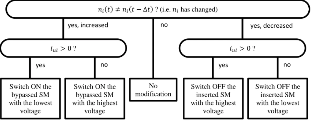
Figure 1-13:Basic BCA flowchart ... 38
Figure 1-14:BCA with Voltage tolerance ... 39
Figure 1-15:Min-Max BCA... 39
Figure 1-16: A general structure of the energy based scheme. ... 41
Figure 2-1: MMC based on the arm-average model ... 45
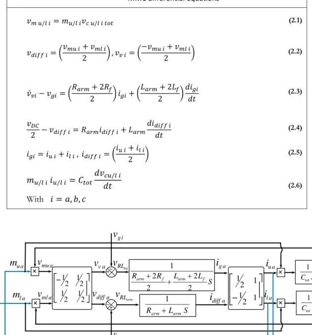
Figure 2-2: Bock diagram of current loops via model inversion ... 46
Figure 2-3: Equivalent model of MMC currents via model inversion ... 48
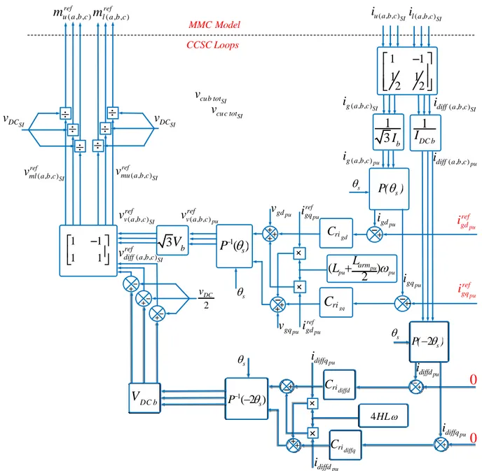
Figure 2-4: MMC Grid current loops in per unit ... 51
Figure 2-5: MMC AC current simulation results. ... 52
Figure 2-6: Spectrum of differential current with AC current control ... 52
Figure 2-7: Structure of circulating current suppression controller in dq frame (CCSC) ... 54
Figure 2-8: MMC AC current simulation results. ... 55
Figure 2-9: Structure of circulating current suppression controller in dq frame (CCSC) with insertion index by 𝐾 𝑣𝐷𝐶 ... 56
Figure 2-10:CCSCdq simulation results by modifying the insertion indices. ... 58
Figure 2-11: Simulation results for an MMC unstable case controlled by CCSC scheme. ... 60
Figure 2-12: MMC Differential current loop ... 61
Figure 2-13: Differential current control simulation results. ... 62
Figure 2-14: Simulation results for MMC with inner current controls. ... 63
Figure 2-15: Comparison of the different types of insert index calculation. ... 65
Figure 2-16: Resonant controller for differential currents in case of linearization by 𝑣𝐷𝐶.. ... 67
Figure 3-1: MMC energy based simulation model ... 71
Figure 3-2: Equivalent up-arm circuit configuration ... 71
Figure 3-3: MMC equivalent model based on instantaneous equations ... 74
Figure 3-4: Whole stored energy equivalent model based on instantaneous equations ... 75
Figure 3-5: MMC equivalent average model ... 77
Figure 3-6: Block diagram of per-phase stored energy controlled by DC link- compensation by𝑝𝐴𝐶 𝑖 ... 79
Figure 3-7: Simulation results for whole MMC stored energy: 𝑊𝑡𝑜𝑡∑, control based on instantaneous MMC model ... 80
Figure 3-8: Block diagram of total MMC stored energy controlled by AC power ... 81
Figure 3-9: Simulation results for whole MMC stored energy: Wtot∑ , control based on instantaneous MMC model ... 82
Figure 3-10: Block diagram of per-phase stored energy controlled by DC link-compensation by 𝑝𝐴𝐶 𝑖 ... 83
Figure 3-11: Simulation results for comparison of the MMC energy control:: 𝑊𝑖∑ controlled with compensation𝑝𝐴𝐶 and: 𝑊𝑖∑ controlled with compensation 𝑝𝐴𝐶 ... 84
Figure 3-12: MMC equivalent model based on per-phase stored energy ... 85
Figure 3-13: Simulation results for control of 𝑊𝑖∆ . ... 86
Figure 3-14: Simulation results for comparison of the MMC energy control:𝑊𝑖∑ controlled ... 88
Figure 3-15: Simulation results for the MMC energy control .(I): 𝑊𝑖∑ controlled by the DC power ,(II)𝑊𝑡𝑜𝑡∑ controlled by the AC power ... 90
Figure 4-1: Point-to point MMC-HVDC transmission scheme ... 92
Figure 4-2: Schematic representation of an HVDC link:(a) Classical VSC applied in an HVDC link and (b) MMC applied in an HVDC link ... 93
Figure 4-3: MMC station connected to a variable DC bus voltage ... 94
Figure 4-4: MMC connected to a variable DC bus voltage when the energy is controlled by the DC power ... 96
Figure 4-5: Energy controlled by the DC power in two cases: ... 97
Figure 4-6: MMC connected to a variable DC link when the energy is controlled by the AC power ... 98
Figure 4-7: Energy controlled by the AC power in two cases: ... 99
Figure 4-8: Block diagram of an MMC with DC voltage control by active power ... 100
Figure 4-9: Comparison results between CCSC and energy-based control with variable DC bus voltage in two cases if DC voltage controlled by AC power ... 101
Figure 4-10: Block diagram of an MMC with DC voltage control by DC power ... 102
Figure 4-11: Simulation results when DC voltage is controlled by DC Power ... 103
Figure 4-12: Two terminals HVDC studied case based on MMC stations ... 105
Figure 4-13: Simulation results for Case A: (𝑆𝐾1 = 1, 𝑆𝐾2 = 2 with 𝐾 = 1)... 107
Figure 4-14: Simulation results for Case B: (𝑆𝐾1 = 2, 𝑆𝐾2 = 2 with 𝐾 = 1) ... 107
Figure 4-15: Simulation results for Case B: (𝑆𝐾1 = 2, 𝑆𝐾2 = 2 with 𝐾 = 1.21) ... 108
Figure 4-16: Simulation results for comparison of the three cases ... 109
Figure A-1 : Step response for different damping values and same response time ... 123
Table 1-1: Comparisons of various SM circuits ... 30
Table 2-1: MMC main equations ... 46
Table 2-2: Parameter of the simulated MMC ... 51
Table 2-3: Parameter for the simulated instable case ... 59
Table 4-1: The electrical circuit parameters considered for the DC cable ... 104
ABSTRACT ... 2
REMERCIMENTS ... 3
RESUME ETENDU ... 4
SYMBOLS & ABBREVIATIONS... 9
LIST OF THE FIGURES & TABLES ... 11
CONTENTS ... 14
INTRODUCTION ... 17
1 Context and Motivation for an HVDC Transmission ... 18
2 Project objectives and outline of this thesis ... 20
3 Scientific contribution of this work ... 21
4 List of publication derived from this work ... 23
CHAPTER 1 : MMC STATE OF THE ART ... 24
1.1 HVDC Converter Topology ... 25
1.1.1. Introduction ... 25
1.1.2. MMC topologies ... 26
1.1.3. Submodules topologies ... 28
1.1.4. Half–bridge SM operating principles ... 30
1.1.5. Description of MMC with half bridge SMs ... 32
1.2 Different Levels of MMC Modeling ... 34
1.3 Low level Control ... 37
1.4 State of art on the High Level Control ... 40
1.4.1. Non energy based control... 40
1.4.2. Energy based control ... 40
1.4.3. Advanced control ... 41
1.5 Conclusion ... 43
CHAPTER 2 : MMC CURRENT CONTROL DESIGN ... 44
2.1 Introduction... 45
2.2 AC Current Control Structure ... 47
2.3 Design of the AC Current Controller ... 48
2.3.1. Structure of the controller ... 49
2.3.2. Design of the AC current controller based on per unit model ... 49
2.3.3. Analysis of the simulation results ... 50
2.4 Circulating Current Suppression Controller (CCSC) ... 53
2.4.1. Expression of the differential current equation in per unit ... 53
2.4.2. CCSC approach analysis ... 55
2.4.3. Focus on an unstable operation point with CCSC... 59
2.5 Differential Current Control ... 60
2.6 Different Solutions for Calculating the MMC Insert Index ... 64
2.7 Resonant Controller for the Differential Currents ... 65
2.8 Conclusion ... 68
CHAPTER 3 : MMC ENERGY BASED CONTROL DESIGN ... 69
3.1 Introduction... 70
3.2 Different Types of MMC Energy-Based Model ... 71
3.2.1. Instantaneous-energy based model ... 72
3.2.1.1. Instantaneous model of the MMC per- phase stored energy ... 73
3.2.1.2. Instantaneous model of the total energy stored in the MMC ... 75
3.2.2. MMC average energy based model ... 75
3.3 MMC Energy Based Control Strategies ... 77
3.3.1. Control of the MMC stored energy ... 78
3.3.1.1. Control of the per phase stored energy based on the instantaneous model 78 3.3.1.2. Control of the MMC total stored energy based on the instantaneous model ... 81
3.3.1.3. Control of the per phase stored energy based on the averaged model ... 82
3.3.2. Control of the difference of the stored energy between up and low arms... 84
3.4 Conclusion and Comparison Between the Different Proposed Strategies ... 87
CHAPTER 4 : CONTROL OF AN HVDC LINK BASED ON MMC ... 91
4.1 Introduction... 92
4.2 Point-to-Point HVDC Link Principles ... 92
4.3 MMC DC Voltage Control Principles ... 93
4.3.1. MMC model associated to a variable DC bus voltage ... 94
4.3.1.1. MMC and DC bus model when the MMC energy is controlled by the DC power ... 95
4.3.1.2. MMC and DC bus model when the MMC energy is controlled by the AC power ... 97
4.3.2. DC bus voltage control ... 99
4.3.2.2. Control by DC Power ... 102 4.4 Control of an HVDC Link ... 104 4.5 Conclusion ... 110 CONCLUSION ... 111 REFERENCES ... 114 APPENDICES ... 121 A. Controller tuning ... 122
A.1. Current controller tuning ... 122
A.2. Power controller tuning ... 123
A.3. Voltage controller tuning ... 123
A.4. PLL tuning ... 124
B. HVDC perunit system ... 125
C. Cable ... 130
1 CONTEXT
AND
MOTIVATION
FOR
AN
HVDC
TRANSMISSION
Over the last century, AC has been the dominant form of electrical transmission systems. Since then, high-voltage AC transmission has some limitations, starting with transmission capacity and distance constrains and the impossibility of directly connecting two AC power networks of different frequencies. With the penetration of the new energy sources and the world global need to transmit more and more energy for the economy growth, high-voltage DC transmission is expected to grow far beyond its traditional position as a supplement to AC transmission.
Nowadays, the HVDC transmission systems are developed as the method for subsea electrical transmission, the interconnection of asynchronous AC grids and in case of any geography constraints. It is also the chosen technology for the long distance power transmission, able to deliver high power with low electrical losses. That makes it a suitable technology in overcoming the problem of decentralization of the production within the renewable generation like wind and solar resources.
With the dawn of a new energy era and the need to build a smarter grid, the European leaders agreed to develop the renewable energies in Europe. The fixed target by the European Council in 2008 [1] is to have a 20 % share of renewable energies in EU energy consumption by 2020.To reach this target, large offshore wind farms have already been installed and others are expected in the coming years, notably in the North Sea due to shallow water. Following EWEA’s recommendations (see Figure 1), the European Network Transmission System Operators (ENTSO-E) has sketched a grid development plan for the next ten years [2]. The scenario proposed by ENTSO-E until 2020 is the building of 9600 km of new HVDC lines in Europe, which should be compared to the 32500 km of new and refurbished HVAC lines. .
Figure 1: EWEA’s 20 year offshore network development master plan [2].
In Europe HVDC transmission has been used since 1954, mostly for submarine cable transmission, as shown Figure 2 [3]. Current HVDC options are: point-to-point link,
back-to-Currently operating offshore cable
Under construction or planned offshore cable Under study by TSO
Under study by TSO/EWEA recommendation Proposed by EWEA in the 2020 timeframe Proposed by EWEA in the 2030 timeframe Proposed offshore node
back link and multi-terminal link (MTDC). The latter configuration is progressing toward the super-grids by interconnecting multiple HVDC and MTDCs associated to large wind farms.
Figure 2: HVDC connections in Europe [3]
HVDC provides efficient, stable transmission and control capability. Definitely the power electronic interfaces between AC and DC system play a key role. Power electronic interfaces are changing through the introduction of new components as transistors. They play an important role to achieve high efficiency and performance in power systems
The use of power electronics in transmission systems is not a new idea since it has been used for decades, but mostly with thyristor components. The first thyristor-based link was built in the early seventies for the Eel River project (2×80 MW). Capacity rose quickly (e.g. the IFA 2000 France-UK link was built in 1986 with a power capability of 2 GW).The capacity of the newest thyristor based links installed in 2013 exceeds 7 GW. Transistors have also been used in HVDC applications for about 15 years, with the first installation on the Island of Gotland at the end of the previous century. These first installations used “simple” 2-level converters. The Cross Sound Cable (330 MW, 150 kV) between Long Island and the American continent was installed in 2002 using a 3-level converter. Because of the high voltage levels, a very large number of transistors are placed in series. However, this large stack of series switches needs to have nearly identical parameters and synchronized ignition to avoid excessive stresses on single components during switching actions. The high frequency switching operation of the PWM (≈1 kHz) was also responsible for significant losses in the range of 3 % per converter for the first generation down to 1.4 % per converter for the 3rd generation PWM based converters [5]
The appearance of VSC-HVDC, having a smaller converter size, reduced filters, dynamic reactive power support and fast power reversal, has facilitated the implementation of HVDC technology in a wider range of applications [6, 7]. Since the first successful application of
VSC-HVDC in 1997 in Gotland, Sweden; many other installations provided asynchronous interconnections of AC grids all-over the world. Due to its smaller footprint and ability to act as a virtual synchronous generator, VSC is especially suitable for connecting offshore wind power plants.
In 2002, Marquardt and Lesnicar proposed the modular multilevel converter (MMC) topology [8]. Due to the fact that it can achieve high power and high voltage levels using proven semiconductor technology, MMC has been widely accepted in the industry [9].The HVDC-from Siemens, HVDC-Light from ABB and HVDC-MaxSine from Alstom are examples of the implementation of the MMC concept in applications for HVDC transmission [10, 11, 12].
With advantages such as modularity, increased efficiency and reliability, the MMCs is now the preferred power electronic topology that has replaced the three-level converters in VSC-HVDC applications, becoming a suitable solution for the VSC-HVDC transmission systems [13].
2 PROJECT OBJECTIVES AND OUTLINE OF THIS THESIS
The motivation for this work is drawn from MMC application for the HVDC transmission. As its name implies, the main characteristics of such a converter topology regards the series connection of dozens to hundreds of identical sub-modules within a branch. This characteristic makes the suitability of MMC application for high power and high voltage transmission. However, the important number of MMC variables creates significant difficulties for synthetizing a control system. With high numbers of level, the control of SMs (balancing SM capacitor voltages) can be separated from the global control (current and power controls) [14, 15].
The aim of this work is to assess the global control of the MMC and its integration in an HVDC transmission system. This work develops and discusses control strategies used for MMC to assume its dynamics. In-depth analyses were performed to achieve control of all MMC states variables. The outline of this thesis is organized as follows:
Chapter 1 is an introduction of MMC topology; it explains the different MMC configurations. Since this topology is complex, two different control levels are distinguished: the control of the switches mainly orientated on the balance of hundreds of voltage on the elementary submodules, the higher level control whose aim is to control the currents, power, and energy in the system. Finally as a step before MMC high-level control, the MMC main parameters are introduced.
Chapter 2 is focused on the control of MMC current variables: the grid and differential currents. Several methods for control of these currents are investigated. A comparison of the presented control with the well-known control scheme of CCSC is provided. At the end of this chapter, different existing methods of linearization in the literature have been discussed and compared.
Chapter 3 investigates the different types of energy based control of the MMC. Firstly different topologies for MMC energy-based model are introduced. Then, the fundamentals of the different control strategies in order to control the stored energy in an MMC are provided. Finally a comparison between CCSC scheme as a well-known MMC control and the proposed energy based control is exposed by simulation results.
Chapter 4 deals with the connection of the two MMC stations in an HVDC link. This chapter is divided in two main sections; one is dealing with the control of the MMC station which controls the DC bus voltage in an HVDC and the other is analyzing interactions caused by its connection to the MMC station which controls the power flow. Once studied the MMC connected to a variable DC-bus, the DC bus voltage control is used to manage the DC-bus voltage and the MMC system dynamics. In the second section, a control strategy based on the MMC energy based control enables to achieve the desired dynamics for DC bus and MMCs dynamic in an HVDC link. This study shows that the way to manage the energy in the MMC may have a critical role in the DC voltage stability in an HVDC link.
Conclusions and perspectives chapter summarizes the work findings, and recommend some improvements and further investigations.
3 SCIENTIFIC CONTRIBUTION OF THIS WORK
Many works have already been achieved on the MMC control with already very good dynamic performances. We do not claim a higher performance of the current or energy controls developed in this PhD but the main contribution of this work is to propose a rigorous methodology to build step by step the control based on the principle of inversion of the model, developed for many years in the lab. The methodology allows identifying clearly all the degrees of freedom in the control and outlines the influence of the choices on the dynamic behavior of an MMC alone or integrated in an HVDC system.
The main contributions of this work are summarized below:
A rigorous methodology to design the current controllers from the MMC model including the discussion on different linearization methodologies (Chapter 2).
The development of the mathematical model of MMC energy variables: per-phased stored energy (𝑊𝑖∑) and per-phased balanced energy (𝑊𝑖∆) (Chapter 3).
Different strategies for control of MMC energy variables: per-phased stored energy (𝑊𝑖∑) and per-phased balanced energy (𝑊𝑖∆) (Chapter 3).
An in-depth analysis on DC–bus voltage variation based on different strategies to manage the energy in the MMC. It may have a critical role in the DC voltage stability in an HVDC link. This analysis has led to the idea of exchanging the MMC stored energy with the DC link which improves the DC bus voltage dynamics (Chapter 4).
A comparison of proposed energy based control and the well-known CCSC scheme for an MMC associated to a variable DC-bus voltage.(Chapter 4).
4 LIST OF PUBLICATION DERIVED FROM THIS WORK
This work has resulted in the following publications:
SAMIMI Shabab, GRUSON François, DELARUE Philippe, GUILLAUD Xavier, COLAS Frédéric P. "Représentation Energétique Macroscopique et Diagramme PQ des Convertisseurs Modulaires Multi-niveaux," in Symposium de Génie Électrique France,2014.
SAMIMI Shabab, GRUSON François, DELARUE Philippe, GUILLAUD Xavier, "Synthesis of different types of energy based controllers for a modular multilevel converter integrated in an HVDC link," in Proc. IEEE ,ADDC Conf. Birmangham,UK,2015.
SAMIMI Shabab, GRUSON François, DELARUE Philippe, GUILLAUD Xavier, "Control of DC bus voltage with a Modular Multilevel Converter," in Proc. IEEE PowerTech. Conf.Eidenhoven,
2015.
GRUSON François, FREYTES Julian, SAMIMI Shabab, DELARUE Philippe, GUILLAUD Xavier, COLAS Frédéric, BELHAOUNE Moez, "Impact of control algorithm solutions on Modular Multilevel Converters electrical waveforms and losses," in 15th EPE ECCE Europe
2015.
SAMIMI Shabab, GRUSON François, DELARUE Philippe, COLAS Frédéric, BELHAOUNE Moez, GUILLAUD Xavier, "MMC stored energy participation to the DC bus voltage control in an HVDC link," Revue,IEEE Trans. Power Del.2016.
1.1 HVDC CONVERTER TOPOLOGY
1.1.1. IntroductionDuring the last years, several multilevel converter topologies, as synthesized on Figure 1-1 [16] have been introduced for high power and medium or high voltage solutions like grid application and electrical drives [17]. The main characteristics of such multilevel converters were to achieve higher power by using power semiconductor switches in series with several lower voltage DC sources to perform power conversion via a staircase voltage waveform. The commutation of the power switches permits the addition of the DC sources which reach high voltage at the output.
Figure 1-1: Multilevel converter topology classification [16]
Compared to two-level converters, multilevel converters present great advantages such as:
Staircase waveform quality: Multilevel converters output voltage improves, the quality of the modulated voltage since the number of levels increases, reducing the total harmonic distortion (THD) and reducing the dv/dt stresses. Therefore electromagnetic compatibility (EMC) problems can be reduced.
Input current: Multilevel converters can draw input current with low distortion. The classical VSC topologies (flying capacitor converter, neutral point clamped converter) were developed long time ago for low voltage or medium voltage electrical drive applications. They were limited to three levels or five levels application at most. The increase on the number of levels was limited by the complexity on the possible topologies.
In the same time, the increase on the DC voltage induced to use many standard switches in series. The Modular Multilevel Converter represents a real breakthrough compared with the previous converters. It brings some new capabilities:
Multilevel Converters Single DC sources Multiple DC sources Neutral point clamped converter Flying Capacitor converter Cascaded H-bridge Converter
Multi-cell topologies Floating capacitor topologies
Modular Multilevel Converter
Modularity quality: MMC stability meets different voltage level requirements
Efficiency: MMC high efficiency is a significant importance for high power applications
Harmonic Performance: MMC has a superior harmonic performance for high voltage applications where a large number of identical SMs with low voltage ratings are stacked up, thereby the size of passive filters can be reduced
1.1.2. MMC topologies
The MMC was initially used for AC/DC applications [8]. Today, although a wide range of applications have been considered, leading to the MMC family [18-21], as illustrated in Figure 1-2
Figure 1-2: Multilevel converter topology classification [18-21]
Figure 1-2 (a) shows cases of the three-phase Cascaded H-Bridge converter in either star or delta configurations whose implementation requires only three converter branches. This topology has started being investigated for static synchronous compensator (STATCOM) applications [22].
Figure 1-2 (b) is the most frequently encountered member of the MMC family proposed by Marquardt in [21]. This variant is used in systems requiring a AC/DC conversion. This topology developed mainly for HVDC systems [23] as well as medium voltage electric drives [24].
b c a b c a a b c u v w a b c Source DC or AC a u c v w b ) a b ) c) d )
The common DC link can be substituted by an AC source. This leads to a single/phase direct AC/AC conversion structure, which can be used for the interconnection of a three-phase industrial grid with a single-three-phase railway supply (16.33 Hz) available in several European countries [20].
Finally, the Hexverter [25] and Matrix converter [26, 27] topologies are shown in Figure 1-2(c) and (d) respectively. These MMC topologies directly connect two three phase systems, for example the supply grid and an electrical machine, in contrast to two DC/AC inverters connected in back-to-back configuration. They seem to be a candidate for AC/AC converters with a low to medium power applications.
Figure 1-3: MMC –hybrid topologies found in the literature
In addition to above topologies in order to achieve more features, such as implementation with a lower number of required submodules, a number of hybrid MMC related topologies have been proposed in literature especially for AC/DC operation such as: the Alternate Arm Converter (AAC) developed by Alstom Grid [28],as well as the MMC with a middle cell [29] as shown in Figure 1-3 (a) and (b) respectively.
Since starting this thesis the available topologies are constantly evolving and changing depends on the pursued objectives. Due to the objective of this thesis, this work deals with the well-known structure labeled as MMC by its inventor illustrated in Figure 1-2(b) which is applied wildly for HVDC systems.
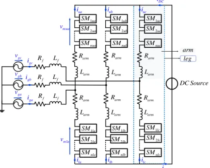
The general structure constituted by three legs, each of them consists of two arms per phase-leg. The upper arm and the lower one are denoted by the sub index “u” and “l” respectively. Each arm comprises N series-connected, nominally identical submodules (SMs) and a series inductor (𝑅𝑎𝑟𝑚, 𝐿𝑎𝑟𝑚), as shown in Figure 1-4. Inside the arms, each submodule is
individually controllable therefore the converter can act as a controllable voltage source, with a large number of available discrete voltage steps. While the SMs in each arm are controlled to generate the required phase voltage, the arm inductor filters the high-frequency components in
a b c
DC Source
)
a
Director Switches a b c b)DC Source
Director Switchesthe arm current and is mainly used in case of DC short-circuit to limit the gradient of the DC current.
Figure 1-4: A general topology of 3-phased MMC 1.1.3. Submodules topologies
Depending on the MMC application and its topology, different types of SMs can be used. 1) The half-bridge circuit or chopper-cell shown in Figure 1-5(a): The output voltage of an
half-bridge SM is either equal to its capacitor voltage
v
c. (switched- on/inserted state) or zero (switched-off/bypassed state), depending on the switching states of the complimentary switch pairs, i.e., S1 and S2. This structure is the most evident choice for AC/DC applications, where only unipolar arm voltage is required. It is simultaneously the simplest option and the one that features the lowest conduction losses [21, 30, 31]. However, the antiparallel diodes are creating an uncontrollable current path in case of a DC-bus short circuit fault, what leads to a unsatisfying behavior under such conditions, as for any other VSC topologies.2) The full-bridge circuit or bridge-cell shown in Figure 1-5(b): The output voltage of a full-bridge SM is either equal to its capacitor voltage 𝑣𝑐 (switched-on/inserted state) or
zeros (switched-off/bypassed state), depending on the switching states of the four switches S1 to S4. Since the number of semiconductor devices of a full-bridge SM is twice of a half-bridge SM, the power losses as well as the cost of an MMC based on the full-half-bridge SMs are significantly higher than that of an MMC based on the half-bridge SMs [21, 32].Certain applications require bipolar arm voltages such as direct AC/AC, matrix topologies or the AAC topology). Since full-bridges can actively break arm currents by imposing appropriate voltages in the arms, they can provide DC short –circuit current breaking capability. However, the double number of power switches almost doubles the conduction losses,
DC Source
1ua
SM
Cou ran t alternatif
Cou ran t alternatif
Cou ran t alternatif
1ub SM 2ub SM 2ua SM nub SM nua SM 1uc SM 2uc SM nuc SM nla SM SMnlb SMnlc 2la SM 1la SM SM1lb SM1lc 2lb SM SM2lc ua i iub iuc la i ilb ilc arm R arm L Larm Larm arm R Rarm arm R Rarm Rarm arm L Larm Larm gc i gb i ga i f R f R f R f L f L f L gc v gb v ga v DC i mua v mla v arm leg DC i
what seriously restrains their attractiveness for AC/DC applications and is the main motivation for the development of the clamped double submodules.
3) The clamp-double circuit shown in Figure 1-5(c): A clamp-double SM consists of two half-bridge SMs, two additional diodes and one extra integrated gate bipolar transistor (IGBT) with its anti-parallel diode. During normal operation, the switch S5 is always switched –on and the clamp-double SM acts equivalent to two series connected half-bridge SMs. Compared to the half- and full-bridge MMCs with the same number of voltage levels, the clamp-double MMC has higher semiconductor losses than the half-bridge MMC and lower than the full-bridge MMC. This cell structure was proposed by Marquardt in 2010 [21] as a specific answer to DC short circuit protection issues. In fact, with an additional switch that can temporarily reconfigure two half-bridges as one full-bridge, the converter arms can impose counter-voltages up to half their nominal blocking voltage. In addition, since the additional switch is not operated in normal conditions, it can be considered with good conduction characteristics and hence, contribute only marginally to the conduction losses [21].
4) The five-level cross-connected circuit shown in Figure 1-5 (d), a five-level cross-connected SM also consists of two half-bridge SMs connected back-to-back by two extra IGBTs with their anti-parallel diodes. Its semiconductor losses are the same as the clamp double SM [33].
Figure 1-5: The MMC main sub-module topologies
A comparison of various SM circuits, in terms of voltage levels, DC-side short-circuit fault handling capability, and power losses, is provided in Table 1-1.
Among all of the SM circuit configurations, the half-bridge topology has been wildly applied in the MMC-HVDC applications. This is due to the presence of only two switches in the SM which results in a lower number of components and higher efficiency for the MMC.
1 D 2 D C vC 2 S 1 S 4 S 3 S 3 D 4 D 1 D 2 D C vC 2 S 1 S 1 D 2 D C vC2 2 S 1 S 4 S 3 S 3 D 4 D 5 S D5 6 D 7 D 1 D 2 D C vC2 2 S 1 S 4 S 3 S 3 D 4 D 7 S ) a 7 D 1 C v 6 S b) c) d) 1 C v D6
Hereafter, the MMC based on the half-bridge SM is considered since the losses are regarded as the first priority in MMC-HVDC applications.
Among all of the SM circuit configurations, the half-bridge topology has been widely applied in the MMC-HVDC applications. However, ULTRANET project in Germany is expected to be realized with full bridge MMC to improve the behavior in case of DC short-circuit [34].This is due to the presence of only two switches in the SM which results in a lower number of components and higher efficiency for the MMC. Hereafter, the MMC based on the half-bridge SM is considered since the losses are regarded as the first priority in MMC-HVDC applications.
1.1.4. Half–bridge SM operating principles
The SMs have three possible states (without short-circuiting the capacitor): • Active state: The IGBT S1 is turned ON while the IGBT S2 is turned OFF.
This SM state leads to two different electrical paths depending on the sign of the current that is entering into the SM (iSM). For a positive current iSM > 0, when the capacitor charges through the diode D1 (Figure 1-6(a)) and for a negative current iSM < 0; when the current is leaving the SM, the capacitor discharges through the IGBT S1 (Figure 1-6(b)). For both cases, the output voltage of the SM will be equal to the voltage of the capacitor vC , hence the SM is considered in the active state, irrespective of the direction of the SM current.
Table 1-1: Comparisons of various SM circuits
SM circuit Voltage levels DC-fault
handling
Losses
Half-Bridge 0, 𝑣𝐶 No Low
Full-Bridge 0,±𝑣𝐶 Yes High
Clamp-double 0,±𝑣𝐶1, ±𝑣𝐶2, (𝑣𝐶1+ 𝑣𝐶2) Yes Moderate
Five–level cross connected 0,±𝑣𝐶1, ±𝑣𝐶2, +(𝑣𝐶1+ 𝑣𝐶2) Yes Moderate
Figure 1-6: The SM active state
1 D 2 D C vC 2 S 1 D 2 D C vC 2 S 1 S mi C v v 1 S S M i S M i 1 , 2 , SM 0 S ON S OFF i S1ON S, 2OFF i, SM0 mi C v v
• Bypassed State: The IGBT S2 is turned ON while the IGBT S1 is turned OFF.
This case, depending on the sign of iSM, has two electrical paths. For positive currents iSM > 0, the current flow will pass through IGBT S2 (Figure 1-7(a)), whereas negative currents will circulate through the diode D2 (Figure 1-7(b)). The bypassed state refers to the voltage output of the SM (𝑣𝑐) which is zero irrespectively of the direction of the current. In this state the
SM capacitor will neither charge nor discharge since it is “isolated” from the rest of the system.
• Blocked State: Both IGBTs S1 and S2 are turned OFF.
For this state, only the free wheel diodes operate and it can be seen in Figure 1-8 that the SM capacitor can be charged through D1 for positive currents and for negative currents the diode D2 offers a path, even if the SM is blocked. It can be conclude that the SM capacitor never can be discharged in blocked state. This state refers to MMC DC short-circuit situations.
Based on mentioned SM normal operations, only active state and bypassed state are considered. A general function of the𝑆𝑀𝑖 based on “SM insertion index” (𝑛𝑖) can be derived as
following:
𝑛𝑖=1 when 𝑆𝑀𝑖 is in active state then 𝑣𝑚𝑖i= 𝑣𝑐
𝑛𝑖=0 when 𝑆𝑀𝑖 is in bypassed state then 𝑣𝑚𝑖= 0
Then it is possible to write general function of SMi capacitor voltage: mi i SMi dv C n i dt (1.1)
Figure 1-7:The SM bypassed state
Figure 1-8:The SM blocked state
1 D 2 D C vC 2 S 1 S ) a 0 mi v 1 D 2 D C vC 2 S 1 S b) S M i iS M 1 , 2 , SM 0 S OFF S ON i S1OFF S, 2ON i, SM0 0 mi v 1 D 2 D C
v
C 1 , 2 S OFF S OFF S M i1.1.5. Description of MMC with half bridge SMs
A three phase MMC converter connected to the grid is depicted in Figure 1-9.
Let the sum of the SMs voltages with in an arm be 𝑣𝑚𝑢/𝑙 𝑖 with phase index of i=a,b,c .
By applying Kirchhoff current and voltage equations to the upper and lower loops of the MMC in Figure 1-9 result in (1.2), (1.3) and (1.4)
g i u i l i i i i (1.2) 2 u i g i DC mu i arm u i arm g i f g i f NO di di v v R i L v R i L v dt dt (1.3) 2 DC l i g i ml i arm l i arm g i f g i f NO di di v v R i L v R i L v dt dt (1.4)
From above equations it is possible to present the MMC in the matrix form:
2 2 u i DC mu i g i NO u i f arm f f arm f f f arm l i f f arm l i DC ml i g i NO di v v v v i L L L dt R R R L L L di R R R i v v v v dt (1.5)
Figure 1-9:The MMC based on half bridge SM
2 DC v 1ua SM SM1ub 2ub SM 2ua SM nub SM nua SM 1uc SM 2uc SM nuc SM nla SM SMnlb SMnlc 2la SM 1la SM SM1lb SM1lc 2lb SM SM2lc ua i iub iuc la i ilb ilc arm R arm L Larm Larm arm R Rarm arm R Rarm Rarm arm L Larm Larm DC i muc v mlc v DC i 1 D 2 D C vC 2 S mi v 1 S S M i mlb v mla v mub v mua v DC v Half bridge Sub Module 2 DC v O N Courant alternatif Courant alternatif Courant alternatif gc i gb i ga i f R f R f R f L f L f L gc v gb v ga v
It can be noticed from (1.5) that the MMC system matrixes are not diagonal which means that the MMC converter is a coupled system. In order to control the inner dynamics as well as to control the AC and DC power exchange in the MMC system, it is interesting to decouple the AC and DC parts.
MMC AC part:
By adding term by term the main equations of (1.3) and (1.4) it can obtain:
2 u i l i 2 2 g i 2 mu i ml i NO arm u i l i arm g i f f g i di di di v v v R i i L v L R i dt dt dt (1.6) MMC DC part:By subtracting term by term the main equations of (1.3) and (1.4) it results:
u i l i 0 DC mu i ml i arm u i l i arm di di v v v R i i L dt dt (1.7)Regarding to (1.2), (1.6) and (1.7) it is possible to present system in the matrix form:
2 2 2 2 2 2 u i f arm f arm l i arm arm u i g i NO mu i ml i f arm f arm l i mu i ml i DC arm arm di L L L L dt di L L dt i v v v v R R R R i v v v R R (1.8)
The matrix diagonalization procedure leads to the variable changes that clearly reveal the MMC inner parameters participate in power exchange between AC grid and DC link.
Matrix diagonalization leads to the following variable changes:
2 u i l i diff i i i i (1.9) 2 mu i ml i diff i v v v (1.10) 2 mu i ml i v i v v v (1.11) v i vi NO v v v (1.12) With: diff
diff
v : MMC inner unbalance voltage of phase i which relates to idiff flows through MMC leg
v i
v : MMC inner AC voltage of phase i
Regarding the above MMC variables, (1.6) and (1.7) can be written as following:
2 2 2 2 g i arm f arm f vi g i g i di R R L L v v i dt (1.13) 2 diff i DC
diff arm diff i arm
di v
v R i L
dt
(1.14)
Representation of the system presented in (1.15) demonstrates the decoupled MMC system:
2 2 0 2 2 1 0 2 f arm g i vi g i gi f arm f arm diff i diff i arm DC diffi arm arm R R di v v i L L L L dt i di R v v L L dt (1.15)It is important to notice that ,since the sum of the grid currents is equal to zero there are 5 state values (𝑖𝑔 𝑎 , 𝑖𝑔 𝑏 , 𝑖𝑑𝑖𝑓𝑓 𝑎 , 𝑖𝑑𝑖𝑓𝑓 𝑏 , 𝑖𝑑𝑖𝑓𝑓 𝑐 ).
1.2 DIFFERENT LEVELS OF MMC MODELING
There are many variables in a MMC due to the high number of IGBTs. Different modeling approaches can be used according to the type of study and required accuracy. Model evolution in decreasing complexity is depicted in Figure 1-10 [35]. It is expected that by decreasing model complexity, computational performance can be increased. Model 1 is the most detailed. Model 2 uses a simplified power switch circuit model. Model 3 makes a simplified arm circuit equivalent.
A. Model 1: Detailed IGBT-Based Model
Figure 1-10:MMC model evolution in decreasing complexity 1
This model considers a detailed representation of power switches. The model presented in [36] uses an ideal controlled switch, based on the half-bridge SM topology, and using the classical V-I characteristics of the power switches besides manufacturer data sheets or field measurements for non-linear characteristics.
High and Low Level controls can be implemented with this model and it is suitable model for switching and conduction losses study with any topological conditions in the converter. Although, the detailed model has a high degree of fidelity and accuracy for related switching studies it requires a large computation time in order to simulate the MMC power system with a large number of SMs. In this thesis this model will be considered as the reference model.
B. Model 2: Equivalent Circuit-Based Model [37]
In this model the SM power switches are replaced by ON/OFF resistors: 𝑅𝑂𝑁(small value
in milliohms) and 𝑅𝑂𝐹𝐹 (large value in mega ohms). This approach allows performing an arm
circuit reduction for eliminating internal electrical nodes and allowing the creation of a Norton equivalent for each MMC arm. The resistances are controlled and used for replacing the two IGTB/diode combinations. With the trapezoidal integration rule, each SM capacitor is replaced by an equivalent current source in parallel with a resistance; where is the numerical integration time-step. The derivation of these equations can be found in [37]. However, the blocked state condition and other implementation details have not been addressed. The main advantage of Model 2 is the significant reduction in the number of electrical nodes in the main system of network equations. The algorithm still considers each SM separately and maintains a record for individual capacitor voltages. It is applicable to any number of SMs per arm.
C. Model 3: MMC Arm Switching Function
In this model, each MMC arm is averaged by using the switching function concept of a half-bridge converter based on equation (1.1) and SM index.
Assuming that there is an ideal capacitor voltage balancing with in each arm, the following assumption can be made:
1 2 tot i C C C C v v v ... v N (1.16)
Where 𝑣𝐶 𝑡𝑜𝑡 represents the sum of all capacitor voltages within an arm. The accuracy of
assumption increases when the number of SMs per arm is increased and/or when the fluctuation amplitudes of capacitor voltages are decreased. This assumption allows deducing an equivalent capacitance 𝐶𝑎𝑟𝑚 = 𝐶 𝑁⁄ for each arm. By defining the switching functions of an arm as follows:
1 1 N i i i n m N
(1.17)Including the linear conductivity losses for each SM, the following switching functions can be derived for each arm when the SMs are in ON/OFF states [38]: