HAL Id: hal-01114383
https://hal.archives-ouvertes.fr/hal-01114383
Submitted on 9 Feb 2015
HAL is a multi-disciplinary open access
archive for the deposit and dissemination of
sci-entific research documents, whether they are
pub-lished or not. The documents may come from
teaching and research institutions in France or
abroad, or from public or private research centers.
L’archive ouverte pluridisciplinaire HAL, est
destinée au dépôt et à la diffusion de documents
scientifiques de niveau recherche, publiés ou non,
émanant des établissements d’enseignement et de
recherche français ou étrangers, des laboratoires
publics ou privés.
Multiple RF Continuous-Wave Generation Using a
Single Signal Generator for Carrier Agrregation in
LTE-Advanced
M. Abdi.Abyaneh, A. Kaissoine, B. Huyart, Jean-Christophe Cousin
To cite this version:
M. Abdi.Abyaneh, A. Kaissoine, B. Huyart, Jean-Christophe Cousin. Multiple RF Continuous-Wave
Generation Using a Single Signal Generator for Carrier Agrregation in LTE-Advanced. European
Microwave Conference (EUMC) 2014, Oct 2014, Rome, Italy. �hal-01114383�
Multiple RF Continuous-Wave Generation Using a
Single Signal Generator for Carrier Agrregation in
LTE-Advanced
M.Abdi.Abyaneh, A. Kaissoine, B. Huyart & J.Cousin
Communication & Electronics Dept Institut Télécom, Télécom-ParisTech, 46 rue Barrault, 75634 Paris cedex 13, France [email protected]
[email protected] [email protected] [email protected]
Abstract— Multiple Continuous-Wave (CW) Radio Frequency (RF) signals are used in many telecommunication applications, such as frequency aggregation in LTE-Advanced (LTE-A), intermodulation distortion measurements and …, in order to use more efficiently the frequency bands that are available. In this work a new method for generating three frequencies and more, with no a-priori condition on the frequency allocation, is elaborated in theory and practical results are presented, as well.
Keywords— frequency aggregation; CW RF signals; multi carrier; LTE-Advanced;
I. INTRODUCTION
LTE-A uses two techniques to obtain a superior data rate than its preceding technologies; Input Multiple-Output (MIMO) and Carrier Aggregation (CA). For downlink transmission a system of up to 8x8 MIMO and for uplink transmission a system of up to 4x4 MIMO should be used depending on the user equipment [1]. CA technique permits us to exploit up to 100MHz distributed bandwidth, using up to five carriers with a maximum of 20MHz bandwidth for each carrier , over the RF spectrum. Hence, the data rates up to 3Gbps in downlink and 1.5Gbps in uplink would be achievable.
There are three types of frequency aggregation; the first one is the contiguous intra-band frequency aggregation in which all the carriers are placed, consecutively, in one frequency band. The second type is the non-contiguous intra-band frequency aggregation in which the carrier intra-bands are not located consecutively in a single band. Finally, the third type is the inter-band frequency aggregation in which the carriers are separated in more than one frequency band [2].
Generating multiple carriers at unequal distances are, normally, performed using multiple signal generators which is not suitable for mobile application, since low battery consumption, cheap fabrication and light weight are important factors in mobile designs. There are several studies that have been made for multiple CW generation; in [3]a
method for generating four CW signals is elaborated with the expense of using four digital signal generators. In [4] 14 consecutive frequency bands are generated at multiples of 528MHz, which might be suitable, with some modifications, only for the case of intra-band CA. Also, in [5]a method for generating coherently phased multiple tones for measuring linear responses over finite bandwidths is proposed, in which an M-tone baseband signal b(t) is created and modulated on the carrier frequency fc:
N n n n
n
ft
A
t
b
1)
2
cos(
)
(
Where N= (M-1)/2, Δf is the frequency spacing between tones and An, αn are amplitude and phase of each tone n. Using this
method one may generate non-contiguous bands by creating many tones and disabling the undesired tones but the tones are always placed at integer multiples of Δf. obviously, this method cannot be the optimum since, firstly, many tones are generated just to be turned off after, secondly, the remaining tones are integer multiples of Δf which does not give us the freedom to generate any frequency that would be desired.
In section II the mathematical procedure to generate a multitone signal with any frequency spacing is elaborated. Then, in section III the practical results supporting the theory is presented in which one 3-tone and one 4-tone signals are generated using a single signal generator and a direct application of this technique in a demodulation process is elaborated. The last part, section IV, contains the conclusion of this work.
II. M-TONE SIGNAL GENERATION METHOD
Let’s take a look at a simple case of generating a 2-tone signal, hence:
)
(
)
(
j2 f1t j2 f2t ee
e
t
x
With x(t) as the RF signal with tones at f1 and f2. By a simple
calculation one may obtain:
) 2 2 ) 2 2 1 2 cos( 2 ( ) ( 2 1 f t f j e t f f e t x
In the case of 3-tone RF signal:
)
3
2
2
2
1
2
(
)
(
t
e
e
j
f
t
e
j
f
t
e
j
f
t
x
Using (3) one can obtain
) 3 2 ) 3 3 (( ) (t e I JQ ej fc t x Where ) 4 2 2 cos( )) 2 2 cos( 2 1 ( ) ( 1 2 1 2 3 3 t f f f t f f t I ) 4 2 2 sin( )) 2 2 cos( 2 1 ( ) ( 1 2 1 2 3 3 t f f f t f f t Q 4 2 3 2 1 3 f f f fc
One may develop the case with 4 tones using the same concept as:
)
)
((
)
(
2 4 4 4 t f j eI
JQ
e
Ct
x
WhereI4(t) I3(t)cos(2 fkt) Q3(t)sin(2 fkt) cos(2 fkt)
()sin(2 ) sin(2 ) 3 ) 2 sin( ) ( 3 ) ( 4t I t f t Q t f t f t Q k k k 8 4 2 3 3 2 1 f f f f fk 8 4 2 3 3 2 1 4 f f f f fc
By continuing this method, any multiple-tone signal can be generated.
III. EXPERIMENTAL RESULTS
A. Signal generation:
Two practical cases were studied to generate 3-tone and 4-tone signal. The in-phase and quadrature components were generated using MATLAB® and loaded to the Agilent EXG vector signal generator N5172B. The downloaded I/Q data were modulated using the I/Q modulator integrated in N5172B. The spectrums are depicted by MATLAB® using the data obtained by the Rohde & Schwarz FSIQ-40 spectrum analyzer
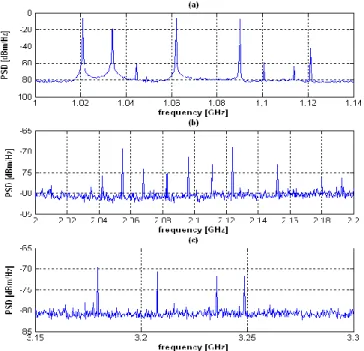
Fig. 1(a) shows the three desired fundamentals at unequally spaced frequencies of 1.021 GHz, 1.034GHz and 1.09GHz. Also, due to nonlinearities of the mixer, that up-converts the baseband signal to RF frequency range, some intermodulation components appear which are not disturbing, since the Spurious Free Dynamic Range (SFDR) is more than 51dB, moreover, in Fig. 1(b) and (c) the 2nd and 3rd harmonics, generated due to mixer nonlinearities, are presented, respectively.
Fig. 1. (a) Fundamental frequencies of a 3-tone signal with frequencies at 1.021 GHz, 1.034GHz and 1.09GHz. (b) Weak 2nd harmonics. (c) Weak 3rd harmonics.
Fig. 2(a) shows the four desired fundamentals that are generated at unequally spaced frequencies of 1.021 GHz, 1.034GHz, 1.062GHz and 1.075GHz, also, due to nonlinearities of the mixer, that up-converts the baseband signal to RF frequency range, same as the case of 3-tone
signal generation, some intermodulation components appear which are not disturbing, since the SFDR is more than 52dB, moreover, in Fig. 2(b) and (c) the levels of the 2nd and 3rd harmonics, generated due to mixer nonlinearities, are shown, respectively.
B. 3-tone signal application
In this section, a 3-tone signal with tones at 2.8 GHz, 2.818 GHz and 2.85 GHz, is applied to the test bench depicted in fig.3, which is a modified version of the test bench in [6], as a Local Oscillator (LO) signal. The 3-tone LO signal must down-convert the 3 RF signals, with bandwidths of 67.5 KHz, at 2.8002 GHz, 2.8187 GHz and 2.8512 GHz to the baseband frequencies at 200 KHz, 700 KHz and 1200 KHz, respectively. Once the signal is down-converted, the demodulation can be proceeded as explained in [6].
Fig. 4 shows the three down-converted RF signals at desired baseband frequencies of 200 KHz, 700 KHz and 1200 KHz. Also, one can observe that the channels are not disturbed by any spurious signal as it was required for the demodulation of the signals in [6].
IV. CONCLUSION
A new method for generating multitone signals with any frequency spacing using a single generator was proposed in this work. The I/Q components of the multitone signal were generated and the baseband signal is modulated using a dummy carrier, which does not appear among the final tones. The experimental results for two cases of 3-tone and 4-tone signals were illustrated, moreover, an application of this technique was given as a 3-tone LO generator in an LTE-A demodulation process.
Fig. 2. (a) Fundamental frequencies of a 4-tone signal with frequencies at 1.021 GHz, 1.034GHz, 1.062GHz and 1.075GHz. (b) Weak 2nd harmonics. (c) Weak 3rd harmonics.
Fig. 3. Test bench for the demodulation of RF signal aggregated in frequency.
Fig. 4. Three clean baseband channels at 200 KHz, 700 KHz and 1200 KHz with no spurious frequency
REFERENCES
[1] “ETSI TS 136 211 V10.0.0 (2011-01) LTE; Evolved Universal Terrestrial Radio Access (E-UTRA); Physical channels and modulation.” .
[2] M. Iwamura, K. Etemad, M.-H. Fong, R. Nory, and R. Love, “Carrier aggregation framework in 3GPP LTE-advanced [WiMAX/LTE Update],” IEEE Commun. Mag., vol. 48, no. 8, pp. 60–67, Aug. 2010. [3] A. K. Lu and G. W. Roberts, “An oversampling-based analog multitone
signal generator,” IEEE Trans. Circuits Syst. II Analog Digit. Signal
Process., vol. 45, no. 3, pp. 391–394, Mar. 1998.
[4] S. Traverso, M. Ariaudo, J.-L. Gautier, I. Fijalkow, and C. Lereau, “A 14-Band Low-Complexity and High-Performance Synthesizer Architecture for MB-OFDM Communication,” IEEE Trans. Circuits Syst. II Express Briefs, vol. 54, no. 6, pp. 552–556, June 2007. [5] L. J. Greenstein and P. Fitzgerald, “Phasing Multitone Signals to
Minimize Peak Factors,” IEEE Trans. Commun., vol. 29, no. 7, pp. 1072–1074, juillet 1981.
[6] A. Kaissoine, B. Huyart, and K. Mabrouk, “Demodulation of aggregated RF signal in three frequencies bands with a unique Rx chain,” in