Mixed matrix membranes based on Pebax
® MH-1657
for gas separation
Thèse
Shadi Meshkat Alsadat
Doctorat en génie chimique
Philosophiæ doctor (Ph. D.)
Mixed matrix membranes based on Pebax
®
MH-1657 for gas separation
Thèse
Shadi Meshkat-Alsadat
Sous la direction :
Denis Rodrigue (directeur de recherche)
Serge Kaliaguine (codirecteur de recherche)
Résumé
Dans ce travail, nous avons réussi à améliorer la perméabilité au CO2, ainsi que la sélectivité
CO2/CH4 et CO2/N2, de membranes à matrice mixte (MMM) à base de
poly(éthylène-b-amide) (Pebax MH-1657) en incluant des cadres métalliques-organiques (MOF) et des additifs aromatiques. La première partie des travaux a porté sur l’ajout de MOF de synthèse (MIL-53 et NH2-MIL-53) au Pebax. Les interactions favorables entre les groupes fonctionnels des MOF et du CO2, ainsi que l’absence de défauts morphologiques majeurs,
ont conduit à une meilleure performance de séparation du CO2 des membranes. Dans la
deuxième partie, une approche différente a été adoptée en étudiant l’effet des acides carboxyliques aromatiques (acide benzoïque et acide isophtalique) sur les membranes planes de Pebax MH-1657. Les groupes fonctionnels carboxyle ont une forte affinité pour le CO2
facilitant le transport du CO2 à travers les membranes conduisant à une sélectivité CO2/CH4
et CO2/N2 plus élevée. Dans la dernière partie, deux MOF isoréticulaires (ZIF-8 et ZIF-67)
ont été introduits dans le Pebax MH-1657 pour modifier ses propriétés discriminantes pour le CO2. Le ZIF-67 s’est avéré plus efficace pour faciliter la diffusion du CO2 en raison de sa
taille plus appropriée d’ouverture des pores, tandis que le ZIF-8 était meilleur pour améliorer la solubilité du CO2 en raison de fortes interactions électrostatiques avec le CO2. Dans
l’ensemble, les résultats obtenus ouvrent la voie au développement de membranes polymères pour la séparation des gaz.
Abstract
In this work, we improved the CO2 permeability, as well as CO2/CH4 and CO2/N2 selectivity, of mixed
matrix membranes (MMM) based on poly(ethylene-b-amide) (PebaxÒ MH-1657) by including
metal-organic frameworks (MOF) and aromatic additives. The first part of the work investigated the addition of as-synthesized MOF (MIL-53 and NH2-MIL-53) in PebaxÒ. The favorable interactions between the
MOF functional groups and CO2, as well as the absence of major morphological defects, led to
improved CO2 separation performance of the membranes. In the second part, a different approach was
adopted by studying the effect of aromatic carboxylic acids (benzoic acid and isophthalic acid) on PebaxÒ MH-1657 flat membranes. The carboxyl functional groups have strong affinity for CO2
facilitating the CO2 transport through the membranes leading to higher CO2/CH4 and CO2/N2
selectivity. In the final part, two isoreticular MOF (ZIF-8 and ZIF-67) were introduced in PebaxÒ
MH-1657 to modify its discriminating properties for CO2. ZIF-67 was found to be more effective in
facilitating CO2 diffusion due to its more appropriate size of pore aperture, while ZIF-8 was found to improve CO2 solubility due to strong electrostatic interactions with CO2. Overall, the results obtained
Contents
Résumé ... ii
Abstract ... iii
List of Figures ... vi
List of Tables ... ix
List of Abbreviations and Acronyms ... x
Acknowledgement ... xii
Foreword ... xiii
General introduction ... 1
Objectives and research contribution ... 12
Structure of this thesis ... 13
1.
Literature review ... 16
1.1. Material selection for mixed matrix membranes for gas separation ... 16
1.2. Homopolymers ... 16 1.2.1. Polyimides (PI) ... 18 1.2.2. Polysulfone ... 22 1.2.3. Polydimethylsiloxane (PDMS) ... 23 1.3. Block copolymers ... 24 1.4. Poly(ether-b-amide): PebaxÒ ... 26 1.5. Fillers ... 28
1.5.1. Metal-Organic frameworks (MOF) ... 29
1.5.2. Mixed matrix membranes based on MIL-53 ... 33
1.5.3. Mixed Matrix Membranes based on PebaxÒ ... 36
1.5.4. Polymer/acid membranes for gas separation ... 42
1.6. Conclusion ... 43
2.
Mixed matrix membranes based on amine and non-amine MIL-53(Al) in
Pebax MH-1657 for CO
2separation ... 44
2.1. Résumé ... 45
2.2. Abstract ... 46
2.3. Introduction ... 47
2.4. Materials and methods ... 50
2.4.1. Materials ... 50
2.4.2. MIL-53 and NH2-MIL-53 Synthesis ... 50
2.4.3. MMM Preparation ... 50
2.4.4. Characterization ... 51
2.4.5. Gas Permeation Test ... 53
2.5. Results and Discussion ... 54
2.5.1. MOF and MMM Characterization ... 54
2.5.4. TGA-DTG ... 60
2.5.5. Density ... 62
2.5.6. Mechanical properties ... 63
2.6. Gas permeation analysis ... 64
2.6.1. Single gas test: Permeability ... 64
2.6.2. Single gas test: Ideal selectivity, diffusivity and solubility ... 68
2.6.3. Mixed gas permeation ... 70
2.6.4. Comparative study between amine and non-amine MOF ... 73
2.7. Conclusion ... 75
3.
Enhancing CO
2separation performance of Pebax MH-1657 with
aromatic carboxylic acids ... 77
3.1. Résumé ... 78 3.2. Abstract ... 79 3.3. Introduction ... 80 3.4. Experimental ... 82 3.4.1. Materials ... 82 3.4.2. Membrane preparation ... 83 3.4.3. Membrane characterization ... 83 3.4.4. Gas permeation ... 84
3.5. Results and discussion ... 85
3.5.1. Membrane characterization ... 85
3.5.2. Gas permeation results ... 93
3.5.3. Comparison between benzoic acid and isophthalic acid ... 102
3.6. Conclusion ... 104
4.
Comparison between ZIF-8 and ZIF-67 in Pebax
®MH-1657 mixed matrix
membranes for CO
2separation ... 106
4.1. Résumé ... 107 4.2. Abstract ... 108 4.3. Introduction ... 109 4.4. Experimental ... 111 4.4.1. Materials ... 111 4.4.2. Synthesis of ZIF-67 ... 111
4.4.3. Mixed matrix membranes fabrication ... 112
4.4.4. MOF and MMM characterization ... 112
4.4.5. Gas permeation ... 113
4.5. Results and discussion ... 114
4.5.1. Characterization of ZIF-67 ... 114
4.5.2. Gas permeation results ... 126
4.5.3. Comparison of ZIF-8 and ZIF-67 in MMM ... 129
4.6. Conclusion ... 131
Conclusion ... 132
Recommendations for future works ... 134
List of Figures
Figure 1. Typical biogas composition [2]. ... 1
Figure 2. Number of biogas upgrading plants per year as of December 2017 [14]. ... 3
Figure 3. A schematic representation of membrane separation [23]. ... 5
Figure 4. Left: Molecular sieving and Right: Solution-diffusion [25]. ... 6
Figure 5. CO2/CH4 Robeson curve [27]. ... 8
Figure 6. (a) SEM image of a MMM [31] and (b) schematic representation of a dense MMM [32]. ... 9
Figure 7. Comparison between glassy and rubbery polymer membranes on a Robeson plot [26]. ... 17
Figure 8. Permeability of CO2 as a function of feed pressure for a typical glassy and rubbery polymer [36]. ... 18
Figure 9. Typical interface between MatrimidÒ/Zeolite 4A MMM [43]. ... 19
Figure 10. Structure of MatrimidÒ [54]. ... 21
Figure 11. Structure of 6FDA-DAM [61]. ... 22
Figure 12. Structure of polysulfone (PSF) [67]. ... 23
Figure 13. PDMS repeating unit. ... 24
Figure 14. Chemical structure of PebaxÒ MH-1657 [83]. ... 27
Figure 15. A typical MOF crystal. The yellow sphere represents the pore cavity [104]. .... 30
Figure 16. Terephthalic acid or BDC [115]. ... 31
Figure 17. Narrow-pore (NP) and large-pore framework of MIL-53 [119]. ... 31
Figure 18. The single crystal structure of ZIF-8 and ZIF-67. Left and center show the sodalite topology, while on the right the largest cage is shown with CoN4 or ZnN4 tetrahedra in blue [108]. ... 32
Figure 19. Left: MIL-53 particles. Right: Cross-sectional SEM image of Matrimid/MIL-53 30 wt.% [124]. ... 34
Figure 20. Top-view (left) and cross-sectional view (right) of CA/NH2-MIL-53 (15 wt.%) [131]. ... 36
Figure 21. The low-magnification (left) and high-magnification (right) structure of a dual-layer membrane [132]. ... 37
Figure 22. The thin selective layer of Pebax/ZIF-7 deposited on PAN with PTMSP as the gutter layer intermediate [135]. ... 38
Figure 23. Structures of free IL dispersed in MMM (left) vs. IL confined in MOF fillers (right) [138]. ... 40
Figure 24. Preparation of ZIF-8@GO [146]. ... 42
Figure 25. Flowchart of the production of the mixed matrix membranes. ... 51
Figure 26. Pebax MH-1657 chemical structure. ... 52
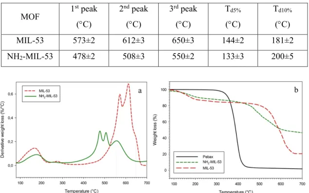
Figure 27. (a) DTG and (b) TGA curves of MIL-53 and NH2-MIL-53. ... 56
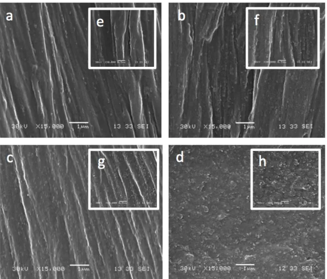
Figure 28. Typical SEM images of the MMM at different magnifications (15K,30K) for: (a,e) 5, (b,f) 10, (c,g) 15 and (d,h) 20 wt.% NH2-MIL-53. ... 57
Figure 29. Typical SEM images of the MMM at different magnifications (15K,30K) for: (a,e) 5, (b,f) 10, (c,g) 15 and (d,h) 20 wt.% MIL-53. ... 58
Figure 30. FTIR curves of MIL-53 and NH2-MIL-53. ... 59
Figure 32. DTG curves for: (a) Pebax/MIL-53 MMM and (b) Pebax/NH2-MIL-53 MMM.
... 62 Figure 33. Single gas permeability of CH4, N2 and H2 and ideal selectivity of CO2/CH4 and
CO2/H2 as a function of MOF loading (wt.%) in: (a) Pebax/MIL-53 MMM and (c)
Pebax/NH2-MIL-53 MMM. Single gas permeability of CO2 and ideal selectivity of
CO2/N2 as a function of MOF loading (wt.%) in: (b) Pebax/MIL-53 MMM and (d)
Pebax/NH2-MIL-53 MMM. All tests were done at 35°C and 10 bar. ... 67
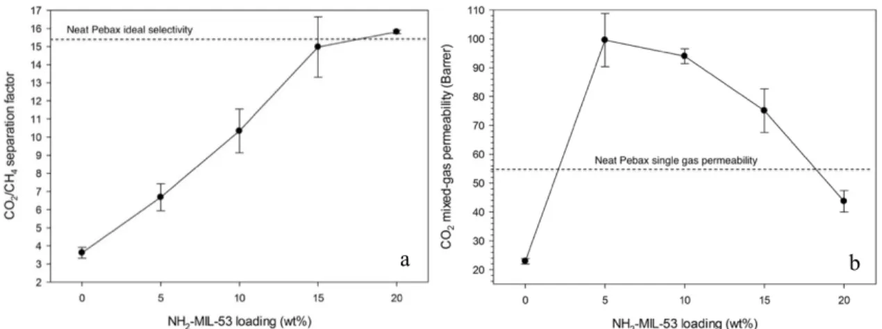
Figure 34. (a) CO2/CH4 (50:50 vol.%) separation factor and (b) CO2 mixed gas
permeability as a function NH2-MIL-53 loading in MMM (35°C and 22 bar total
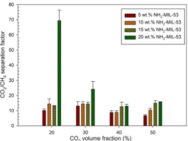
upstream pressure). ... 71 Figure 35. Effect of CO2/CH4 feed gas composition on the binary mixture separation factor
(35°C and 22 bar total upstream pressure). ... 73 Figure 36. Comparison between: (a) CO2/N2 ideal selectivity and (b) single CO2
permeability of amine and non-amine MMM. ... 74 Figure 37. Performance of the as-synthetized MMM with optimum MOF loading on
Robeson plot. ... 75 Figure 38. Chemical structure of: (a) PebaxÒ MH1657, (b) benzoic acid and (c) isophthalic
acid. ... 83 Figure 39. FTIR spectra of: (a) mid-range bands of Pebax/B membranes, (b) mid-range
bands of Pebax/I membranes, (c) high-range bands of Pebax/B membranes and (d) high-range bands of Pebax/I membranes. ... 87 Figure 40. TGA curves of: (a) Pebax, benzoic acid and Pebax/B-8 membrane, (b) Pebax,
isophthalic acid and Pebax/I-8 membrane and (c) DTG curve of Pebax/B-8 and
Pebax/I-8 compared to neat Pebax. ... 89 Figure 41. DSC thermographs of neat Pebax, Pebax/I and Pebax/B membranes. The Tg of
PEO soft segment of each membrane is encircled. ... 90 Figure 42. Schematic view of interactions between CO2, N2 and CH4 with benzoic acid
[238]. ... 95 Figure 43. Effect of acid content on CO2 permeability, as well as CO2/CH4 and CO2/N2
selectivity for: (a) Pebax/B and (b) Pebax/I membranes at 10 bar and 35°C. ... 96 Figure 44. Effect of operating pressure on CO2 permeability for: (a) Pebax/B and (b)
Pebax/I membranes at 35°C. ... 98 Figure 45. Effect of temperature on permeation at 10 bar. Ln P of CO2 for: (a) Pebax/B
membranes and (b) Pebax/I membranes versus (1/T) *1000. Variation of apparent activation energy of permeation with acid content for different gases: (c) Pebax/B membranes and (d) Pebax/I membranes. ... 100 Figure 46. Effect of temperature on CO2/CH4 selectivity of: (a) Pebax/B and (b) Pebax/I
membranes, as well as CO2/N2 selectivity of: (c) Pebax/B and (d) Pebax/I membranes
at 10 bar. ... 101 Figure 47. Diffusivity and solubility coefficients of CO2 in Pebax/I and Pebax/B
membranes. ... 102 Figure 48. Performance of Pebax/I and Pebax/B membranes for: (a) CO2/N2 and (b)
CO2/CH4 separation. ... 104
Figure 49. The chemical structure of ZIF-8, ZIF-67 and their crystal [109]. ... 115 Figure 50. SEM images of: (a) ZIF-8 and (b) ZIF-67 particles. ... 116
Figure 51. N2 adsorption and desorption isotherm as well as pore size distribution (DFT
method) of ZIF-67. *The ZIF-8 data is taken from [269]. ... 116 Figure 52. Particle size distribution of ZIF-8 and ZIF-67 obtained from DLS analysis. ... 117 Figure 53. (a) Thermogravimetric analysis (TGA) and (b) derivative of thermogravimetric
analysis (DTG) of ZIF-8 and ZIF-67. ... 117 Figure 54. FTIR spectra of: (a) ZIF-8 and (b) ZIF-67. ... 118 Figure 55. XRD pattern of ZIF-8 and ZIF-67 at ambient temperature. ... 118 Figure 56. Cross-sectional SEM image of: (a) Pebax/ZIF-8 (2) and (b) Pebax/ZIF-67 (5).
(c) Pebax/ZIF-67 (5) casting solution after resting for 24 h showing good stability. 119 Figure 57. DSC curves of neat Pebax and typical Pebax/ZIF-8 and Pebax/ZIF-67 MMM.
The curves are shifted vertically for clarity. ... 121 Figure 58. TGA-DTG curves of neat Pebax and typical 8 (a,b) and
Pebax/ZIF-67 (c,d) from 200 to 450°C in nitrogen. ... 122 Figure 59. FTIR spectra of neat Pebax, Pebax/ZIF-8 (a) and Pebax/ZIF-67 (b) MMM. The
spectra between 1800 and 2700 cm-1 was removed due to the absence of significant
peaks in this region. The curves are shifted vertically for clarity. ... 124 Figure 60. Effect of filler loading on CO2 permeability and CO2/N2 and CO2/CH4 ideal
selectivity of: (a) Pebax/ZIF-8 and (b) Pebax/ZIF-67 at 35 °C and 11 bar. ... 129 Figure 61. CO2 diffusivity coefficient of the MMM as a function of filler content. ... 129
Figure 62. Performance of the MMM on Robeson plots for: (a) CO2/CH4 and (b) CO2/N2.
List of Tables
Table 1. Types of block copolymers with commercial examples [68]. ... 25
Table 2. List of PebaxÒ MH-1657/MOF MMM prepared for CO2 separation. ... 49
Table 3. Physical properties of MIL-53 and NH2-MIL-53. ... 55
Table 4. Characteristic decomposition temperatures of MIL-53 and NH2-MIL-53 obtained from TGA-DTG. ... 56
Table 5. Thermal properties of the membranes as obtained by TGA and DTG. ... 61
Table 6. Density and FFV for Pebax/MIL-53 and Pebax/NH2-MIL-53 MMM. ... 63
Table 7. Tensile properties of membranes. ... 64
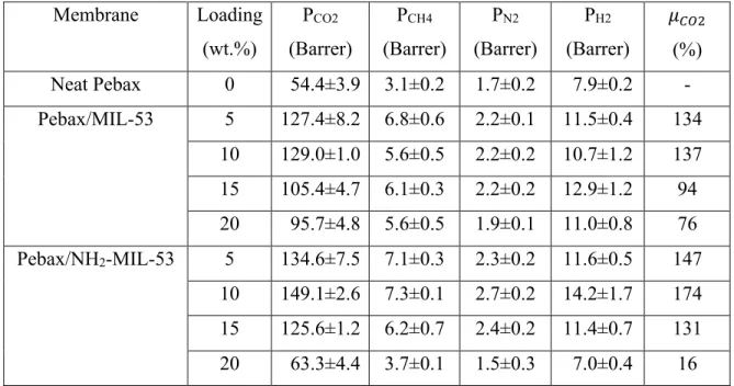
Table 8. Permeability of different gases in the membranes (35°C and 10 bar). ... 65
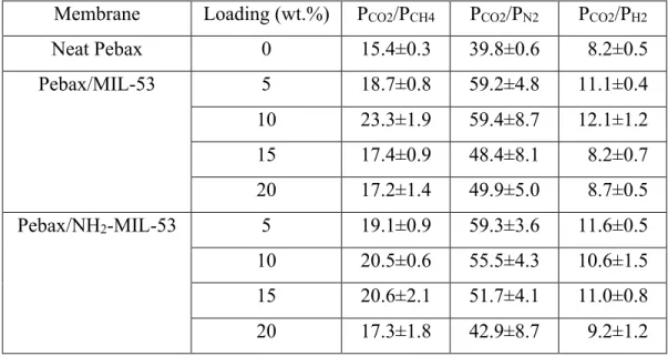
Table 9. Ideal selectivity of CO2 over CH4, N2 and H2 (35°C and 10 bar). ... 69
Table 10. Diffusivity (10-7cm2 s-1) and solubility (10-3 cm3 (STP) cm-3 cmHg-1) coefficients of the membranes (35°C and 10 bar). ... 70
Table 11. Mixed gas permeation results for 10 wt.% and 20 wt.% Pebax/NH2-MIL-53 MMM as a function of CO2 volume fraction in a binary mixture of CO2:CH4 (35°C and 22 bar total upstream pressure). ... 73
Table 12. Density and FFV of neat Pebax, Pebax/B and Pebax/I membranes. ... 91
Table 13. Tensile properties of the membranes. The results are the average of three tests with the highest standard deviation being ±15%. ... 93
Table 14. Permeability and selectivity of the membranes at 10 bar and 35°C. ... 96
Table 15. DSC analysis and thermal properties of Pebax-based MMM. ... 121
Table 16. Density and FFV values of neat Pebax, Pebax/ZIF-8 and Pebax/ZIF-67 membranes. ... 125
Table 17. Gas permeability, ideal selectivity, CO2 diffusivity and CO2 solubility coefficient at 35°C and 11 bar. ... 127
List of Abbreviations and Acronyms
6FDA-DAM 6FDA: 2,2′-Bis(3,4-carboxyphenyl) hexafluoropropane dianhydride; DAM:
diaminomesitylene)
AFM Atomic-Force Microscopy APT Attapulgite
BDC benzene 1,4-dicarboxylic acid BTC benzene tricarboxylate
CA Cellulose Acetate
CMS Carbon Molecular Sieve CNT Carbon Nanotube
DMA Dynamic Mechanical Analysis DSC Differential Scanning Calorimetry EO Ethylene Oxide
FFV Fractional free volume
FTIR Fourier Transform Infrared Spectroscopy GO Graphene Oxide
IL Ionic Liquid
MMM Mixed Matrix Membrane MOF Metal-Organic Framework PA Polyamide
PALS Positron annihilation lifetime spectroscopy PAN Polyacrylonitrile
PBT Poly(butylene terephthalate) PDMS Polydimethylsiloxane PEG Polyethylene glycol PES Polyethersulfone PI Polyimide
POSS Polyhedral oligomeric silsesquioxane PSF Polysulfone
PTMO Poly(tetramethylene oxide)
PTMSP Poly[1-(trimethylsilyl)-1-propyne] PU Polyurethane
PVDF Polyvinylidene fluoride SEM Scanning Electron Microscopy TDI 1,4-toluene diisocyanate
TEM Transmission Electron Microscopy Tg Glass transition temperature
TGA Thermogravimetric Analysis XRD X-ray Powder Diffraction ZIF Zeolite Imidazolate Framework
Acknowledgement
First, I would like to express my gratitude to Prof. Denis Rodrigue and Prof. Serge Kaliaguine, my supervisors, for their academic guidance, support and encouragement throughout my doctoral program. They trusted me in pursuing my own way through my project but always allocated time to discuss the ideas and troubleshoot problems.
I would like to thank my colleagues, Dr. Hoang Vinh Thang, Dr. Tien Binh Nguyen and Amin Biriaei in Prof. Kaliaguine Lab, who helped me preparing and characterizing MOF, and my colleagues in Office 0570 for all their supports. I would also like to thank Dr. Xiao Yuan Chen for her valuable comments during my experiments. Thanks to Yann Giroux for his great help in Prof. Denis Rodrigue lab.
I would also like to thank the Research Center on Advanced Materials (CERMA) and the Natural Science and Engineering Research Council of Canada (NSERC) for technical and financial support for this study.
Foreword
The work for this PhD thesis was carried out during 2015-2018 in the Department of chemical engineering of Université Laval. This thesis comprises six chapters starting with a general introduction and ending with a conclusion and recommendations for future works. Chapter 1 presents a literature review while chapters 2-4 present the main results in the form of articles submitted/published in scientific journals. The list of articles and their status of publication is included in this thesis are:
1. Shadi Meshkat, Serge Kaliaguine, Denis Rodrigue
“Mixed matrix membranes based on amine and non-amine MIL-53(Al) in Pebax®
MH-1657 for CO2 separation”,
Separation and Purification Technology, 200 (2018) 177-190.
2. Shadi Meshkat, Serge Kaliaguine, Denis Rodrigue
“Enhancing CO2 separation performance of Pebax® MH-1657 with aromatic carboxylic
acids”,
Separation and Purification Technology, 212 (2019) 901-912.
3. Shadi Meshkat, Serge Kaliaguine, Denis Rodrigue
“Comparison between ZIF-8 and ZIF-67 in Pebax® MH-1657 mixed matrix membranes
for CO2 separation”,
Separation and Purification Technology submitted (2019).
Shadi Meshkat-Alsadat (the first author of the above articles) was responsible for planning and conducting all the experiments, as well as interpretation of the experimental results and writing the initial drafts manuscripts, in collaboration with Prof. Rodrigue and Prof. Kaliaguine who performed manuscripts revision.
General introduction
Global warming and climate change have raised quests for sustainable energy sources to substitute fossil fuels as the primary source of energy. Biogas is generated from landfills, manure and agricultural waste, waste water treatment plants, sewage sludge and organic fraction of household and industry waste through anaerobic digestion [1]. Biogas is composed of 45-70% methane, 30-45% carbon dioxide as well as small amounts of nitrogen, hydrogen sulfide, hydrogen, ammonia , oxygen and traces of volatile organic compounds and siloxanes (Figure 1) [2].
Figure 1. Typical biogas composition [2].
As the main component of biogas is methane, it is usually referred to as biomethane and is consequently considered to be a potential renewable energy source. Methane is known to be a clean and valuable source of energy. Equally important, it is categorized as a harmful greenhouse gas much more effective than CO2 [3]. Consequently, either the biogas is
intended to be emitted to the atmosphere (the flue gas released from landfill) or to serve as a renewable energy source. In both cases, its methane content should be removed due to the methane’s severe greenhouse gas effect, or to remove the impurities such CO2, N2, H2S to
enhance the biogas calorific value [4]. The upgraded biogas, also known as biomethane, can subsequently be used in various applications. As a typical application, the upgraded biogas
can also be used for injection in to the natural gas grid [5]. At a smaller scale, the biogas generated by anaerobic digestion of the organic-based agricultural wastes could be cleaned and used on-site for the farms power needs. Furthermore, the by-product of this process is a digestate which can be used as fertilizer in agriculture [6]. Moreover, based on European Union reports, 21% of the greenhouse gas emission is attributed to transportation [7]. Hence, there is an emerging interest in upgrading biogas to biomethane to be used as vehicle fuel in Nordic and European countries such as Sweden, Switzerland, and Germany [8]. The environmental benefit of biogas is the highest when it is used as a vehicle fuel. This fact accounts for significant reduction in the emission of air pollutants such as NOx and SOx, as
well as substantial greenhouse gas emission decreases. When replacing natural gas by biogas in large heat or power production plants, the environmental benefit is less important and sometimes economically difficult to justify [9].
Generally speaking, upgrading biogas or biogas cleaning means CO2 removal, which is
abundantly present, as well as H2S, water, siloxanes, volatile organic compounds and other
trace impurities. Among the impurities with adverse effects in the biogas generated in sewage treatment plants and landfill are siloxanes, which wear down the internal parts of the machines, damaging them and reducing their useful life, as well as increasing operation costs due to repeated oil changes and internal parts replacement. Siloxanes come from the silicones present in materials such as shampoo, soaps, surfactants, oils and pharmaceutical products which are subject to anaerobic digestion processes.
Among all these impurities, CO2 and H2S are the most problematic because of their lower
calorific value and most importantly corrosive nature. H2S is removed by either dry oxidation
or liquid phase absorption [10]. Dry oxidation is the process of sulfide oxidation to sulfur and is appropriate when the biogas has low sulfur content. In liquid phase absorption, sulfide gases are absorbed in proper solvents like water or amines [11]. For CO2 removal, several
separation technologies can be applied. The main technologies are amine scrubbing in which various combinations of amines are used, and water scrubbing [12]. Also, pressure swing adsorption is in service for biogas cleaning which normally uses adsorbents like molecular sieves to separate CO2 or other impurities [13]. Last but not least, membrane separation for
the removal of CO2 or other gaseous impurities from biogas has attracted major attention
small-scale plants. Based on the last report published by IEA Bioenergy Task 37, functioning within the framework of International Energy Agency (IEA) in December 2017, the number of biogas upgrading plants in Europe combined with Australia, Brazil, and Korea have substantially increased in recent years as presented in Figure 2 [14]. In particular, the share of membrane upgrading plants has increased with a reasonable rate and now makes up about 25% of the operating plants worldwide.
Figure 2. Number of biogas upgrading plants per year as of December 2017 [14]. Among all separation technologies, membrane separation has gained an important place in research and technology [15]. Membranes are attractive due to their ability to control the permeation rate of a specific chemical species through their cross-sections. Membranes have fundamental engineering and economic advantages such as low energy consumption, mild operating conditions, portability, compactness, continuous separation, easily-up-scaled, simplicity and adjustable properties [16,17]. In addition, it is worth mentioning that an important advantage of membrane separation for biogas upgrading is much smaller equipment footprint compared to amine scrubbing as a widely used technology, in which solvent regeneration is a major issue. Despite their compelling potentials, at the present time, membranes are not competitive with large units or where high purity is required [18]. Also, some pre-treatments are required in membrane technology, mainly including particle
0 100 200 300 400 500 600 <2001 2001 2002 2003 2004 2005 2006 2007 2008 2009 2010 2011 2012 2013 2014 2015 2016 2017 No . o f up gr ad in g pl an ts
Water Scrubber Chemical Scrubber Membrane
PSA Organic physical scrubber Other + unknown
removal and dehydration to avoid water condensation inside the membrane system, imposing additional operational costs. Membranes also suffer from low thermal and chemical resistance and they are not appropriate for reaching high purities. Keeping all these negative points in mind, one interesting advantage of membrane technology, which can be used as a way to tackle its drawbacks, is the possibility of combining membrane technology with other separation treatments to optimize the overall process from both cost and environmental aspects [19]. Besides, due to their easy operation, membranes are excellent candidates for small scale separation units such as biogas cleaning in farms to achieve energy sustainability [6].
From a historical point of view, the first known study on gas permeability was carried out by Thomas Graham and dates back to the 1850s. He measured the permeability of different gases over 20 years and proposed the first theory about gas solution- diffusion [20]. Later on, in the 1950s, Barrer made the first systematic study of gas permeability and established the basis of the current theory of gas permeability through the solution-diffusion model [21]. The first industrial implementation of membrane technology in gas separation was done by Monsanto for the separation of hydrogen from the purge-gas streams of an ammonia plant by means of PRISM® membranes in 1980. PRISM® which were fabricated based on the development of anisotropic membranes by Loeb-Sourirajan [22]. These membranes were able to provide high gas flux leading to the development of hollow-fiber and spiral wound modules, which substantially improved the membrane gas productivity [15]. After the success of PRISM®in the 1980, other companies developed membrane plants for CO2
removal from natural gas, such as Cyanara, Separex and Grace Membrane Systems using cellulose acetate (CA) as the membrane material. For instance, Dow chemicals launched its first commercial membrane system for the separation of nitrogen from air. The success of these companies in the market encouraged the development of new materials with higher selectivities by Ube, DuPont and Air Liquide paving the way for further membranes expansion and application [31].
The principle of membrane separation is its ability to control the permeation rate of a chemical specie. In fact, species are separated by a membrane based on the rate at which they can pass through the membrane. In gas transport, the fact that the membrane is dense, porous
or even a combination of both plays a key role in determining the parameters that directly or indirectly affect the gas transport, as well as the mechanisms governing their transport. A pressurized feed gas is introduced to the high-pressure face of the membrane. The gas flow on the other side of the membrane and enriched of the more permeable component is called the permeate and the gas flow on the same side of the membrane and deprived of the permeating component is called the retentate as shown in Figure 3.
Figure 3. A schematic representation of membrane separation [23].
In dense polymeric membranes, gas transport is governed by the solution-diffusion mechanism: the separation is based on the solubility and the mobility of each gas molecule inside the membrane. In the solution-diffusion mechanism, it is assumed that the gas dissolves in the membrane from the high-pressure side, then diffuses through the membranes and desorbs on the low-pressure side. In porous membranes, the dominant mechanism is molecular sieving, in which the molecular discrimination is based on shape and size [24]. To put it differently, the way gases permeate through the membranes strongly depends upon both the membrane pore size and gas kinetic diameters [15]. In Figure 4, the two afore-mentioned gas transport mechanisms are displayed.
Figure 4. Left: Molecular sieving and Right: Solution-diffusion [25].
Permeability (P) is empirically defined from the steady state gas flux (N) through a membrane of thickness (l), while applying a specific pressure drop (Dp) across the
membrane:
𝑃 = 𝑁(&'% ) Eq. 1 The common unit of permeability in symmetric membranes is a non-SI unit called the Barrer defined as:
1 𝐵𝑎𝑟𝑟𝑒𝑟 = 1 × 10123 456(789) 45
45:; 45<= Eq. 2
This unit is defined based on empirical equations. For asymmetric membranes, permeance is usually reported which is the permeability per unit of membrane thickness and the unit is GPU:
1 𝐺𝑃𝑈 = 1 × 101@ 456(789)
45: ; 45<= Eq. 3
By applying Fick’s law and by assuming that the polymer in the membrane is immobile and the permeate side is vacuumed, permeability is the product of diffusivity D and solubility S as:
𝑃 = 𝐷 𝑆 Eq. 4 Another key parameter in membrane separation performance is selectivity. In the case of single gas permeation, it is defined as the ideal selectivity (𝛼DE) which can also be divided
𝛼
DE=
9F 9G=
HF HG×
7F 7G Eq. 5In binary mixed gas tests, the selectivity is termed the separation factor (𝛼DE∗):
𝛼DE∗ = (𝑦D 𝑦 E
K ) × (𝑥EK ) Eq.6 𝑥D where x and y represent the mole fractions of each component in the feed and permeate, respectively.
In terms of performance comparison between different polymeric membranes, Robeson introduced a diagram of selectivity as a function of permeability for the most permeable component for several gas pairs. In 1991, he proposed that all polymer membranes have an “upper bound behavior”, meaning there is a trade-off between these parameters; i.e. by improving permeability, the selectivity drops and vice-versa. Consequently, he drew an “upper-bound” line for each gas pair, based on the experimental data available at that time and the position of the upper-bound represents the best visual fit to the available data. In order to overcome the “upper bound”, both permeability and selectivity are to be simultaneously enhanced for a membrane. Since then, the target of all membrane scientists is to produce membranes with superior separation performance to surpass the “upper bound” trade-off line [26,27]. In 2008, Robeson revised his diagrams as some membranes had overcome the 1991 “upper bound” line. Figure 5 shows the 2008 revised Robeson plot for the CO2/CH4 gas pair.
Figure 5. CO2/CH4 Robeson curve [27].
One approach to target the limitations imposed by the trade-off behaviour of polymeric membranes was by introducing a novel class of membranes designated as mixed matrix membranes (hereafter MMM), which have been explored since the 1970s when Paul and Kemp reported a delayed diffusion time lag for CO2 and CH4 while incorporating zeolite 5A
in polydimethylsiloxane [28]. In general, this hybrid membrane is composed of a polymer matrix (organic phase) as the continuous phase and a filler (usually an inorganic phase) as the dispersed phase. With this in mind (the polymer matrix forms the continuous phase), it is obvious that the gas transport properties in these membranes are mainly governed by the solution-diffusion mechanism. Both polymer and inorganic materials are inherently potential candidates for membrane preparation solely, but practically speaking, each one suffers from specific drawbacks. The principal idea behind the introduction of MMM is combining the processability, low cost and acceptable mechanical properties of polymers with superior separation performance and high thermal/chemical resistance of inorganic fillers. In short, MMM exploit the superior characteristics of polymers and inorganic materials as membranes, while overcoming the downsides of one another simultaneously. It is worth
mentioning that the gas separation performance of MMM is determined not only by the intrinsic properties of its constituents (polymer and filler), but also by the quality of the polymer-filler interface region [29]. A SEM image and a schematic representation of MMM is shown in Figure 6. The most popular polymers used in MMM are from a wide range of glassy and rubbery polymers such as polysulfone (Udelâ), polyethersulfone, cellulose acetate (CA), polydimethylsiloxane (hereafter PDMS), polyimides (Matrimidâ, 6FDA-based), polyetherimide (Ultemâ), etc. Alternative fillers being considered in MMM applications are carbon molecular sieves (CMS), metal-organic frameworks (hereafter MOF), zeolites, nonporous silica, etc. [30]. These materials will be further discussed in Chapter 2.
The conventional MMM fabrication method is solution casting, also known as solvent evaporation. While the details of the method might be different, the main steps are dissolving a polymer in a proper solvent followed by filler dispersion in the solution. Subsequently, the solution is sonicated and casted by hand or a doctor blade on a non-stick levelled surface. Finally, the solvent is evaporated under ambient conditions or in an oven.
Figure 6. (a) SEM image of a MMM [31] and (b) schematic representation of a dense MMM [32].
Various configurations have been introduced for gas transport membranes, based on the market requirements, and we divide them to two large categories of symmetric and asymmetric membranes.
Symmetric membranes consist of a uniform structure across their thickness. Dense membranes are the most studied membranes of this group to date and are extensively used as a starting point for any new material developed for gas separation membranes at the laboratory scale. They usually provide high selectivity but low productivity. Their separation mechanism is mostly solution-diffusion. So the gas molecules can be separated not only by their molecular size and shape, but also by their solubility in the polymer membrane. Dense membranes are fabricated either by melt extrusion or solution casting. In melt extrusion, the polymer is melted at high temperature to shape it as a dense flat sheet. This method is solvent-free. In the solution casting method, the polymer is dissolved in a proper solvent and the polymeric dope is casted by a doctor blade or by hand on a flat leveled surface. By applying special drying protocols, the solvent is evaporated to give a flat dense membrane.
In contrast to symmetric membranes, asymmetric membranes consist of a micrometer thick selective layer supported by a thick porous substrate. The substrate provides sufficient mechanical support for the thin active layer. These types of membranes are usually prepared by phase inversion. In this method, a polymer dope is casted on a supporting layer and then submerged in a coagulation bath containing a non-solvent for a few moments to trigger a solvent/non-solvent exchange. Further elaboration on this method can be found in the literature [19]-[21]. In general, asymmetric membranes can be grouped into the following four basic structures [22]:
1. An integrally asymmetric membrane with a porous skin layer. 2. An integrally asymmetric membrane with a dense skin layer. 3. A thin-film porous composite membrane.
4. A thin-film dense composite membrane.
Groups 1 and 2 are made up of one material, while groups 3 and 4 are made up of at least two different materials.
Hundreds of thousands of square meters of membrane are required to perform the necessary separation tasks in industrial plants. There are several efficient and economical ways to create a large surface area in a membrane module for an effective gas separation. All module types applied for gas separation are based on two types of membrane configurations such as flat
and tubular. Modules based on flat membranes are the plate-and-frame and spiral-wound modules. Tubular-type membrane modules are subdivided into tubular, capillary, and hollow fiber. The differences between tubular, capillary, and hollow fiber modules are their tube’s dimensions [22]. Membrane configuration also depends on the nature of the materials. Glassy polymers are commonly formed into high-performance anisotropic (skinned) membranes by varying the solution precipitation procedure invented by Loeb and Sourirajan [22]. In contrast, rubbery polymer membranes made by this method would collapse under the high pressure used for gas separation processes. Hence, rubbery polymer membranes are formed as composite structures consisting of a mechanically strong, highly permeable microporous support layer coated with a thin film on the selective rubbery material. Hollow fibers are self-supporting and bound together at the free ends with agents such as epoxy resins. Feed flow can go through the bores, with the permeate exiting the membrane sideways, or can run through the fibers on the outside with the permeate exiting through the bores of the membrane. Asymmetric hollow fibers are attractive for membrane-based gas separation, since they provide high active surface area-to-volume ratio, low resistance to gas flow and the ability to support high pressure drops.
Objectives and research contribution
The aim of this thesis is improving the CO2 separation performance, as well as thermal and
mechanical properties, of poly(ether-b-amide) (Pebax® MH-1657). In particular, the
above-mentioned aim is fulfilled through two approaches:
- Exploring MOF as CO2-selective fillers of Pebax-based MMM and comparing them,
- Proposing effective additives to Pebax to enhance its separation properties in the absence of filler.
The target of the membrane research groups in improving polymeric membranes is to overcome the revised Robeson upper-bound trade-off (2008), and subsequently fabricating a commercially attractive membrane. Nevertheless, despite intensive efforts, several challenges are yet to be addressed in this domain. Including MOF in polymeric membranes opens up new horizons to the enhancement of hybrid gas separation membranes, to use the exceptional gas separation properties of MOF. In this work, a number of MOF, known to be effective for CO2 separation, are studied while incorporated in a polymer, known to be
Structure of this thesis
General introduction
This part provides fundamental information and the concepts underlying this thesis, including the objectives and the research contribution to the membrane field.
Chapter 1 Literature review
This chapter includes a thorough review on the conventional polymers and MOF recently used to prepare mixed matrix membranes for gas separation.
Chapter 2 Mixed matrix membranes based on amine and non-amine
MIL-53(Al) in Pebax
®MH-1657 for CO
2
separation
This chapter studies the properties of MMM based on Pebax® as the matrix and
MIL-53(Al)/NH2-MIL-53(Al) metal-organic frameworks (MOF) as fillers, prepared by solution
casting. The objective of the work is to determine the effect of MOF functionalization and concentration on the permeability and selectivity of different gases (CH4, N2, H2 and CO2).
Various characterizations including scanning electron microscopy (SEM), Fourier transform infrared spectroscopy (FTIR), thermogravimetric (TGA) and dynamic mechanical (DMA) analyses confirm that good particle dispersion up to the optimum content is obtained, and the MOF are successfully included in the MMM. Also, the MMM thermal and mechanical stability are verified to be sufficient for industrial operation. Finally, the gas separation performances are investigated via single gas and mixed gas permeation tests at 35°C and 10 bar. The results show that CO2 single gas permeability, as well as CO2/CH4 and CO2/N2 ideal
selectivity, are enhanced by introducing either MIL-53(Al) or NH2-MIL-53 (Al), while the
highest CO2 permeability (149 Barrer) is obtained at 10 wt.% NH2-MIL-53 with a 174%
improvement over the neat Pebax value. The highest ideal selectivity for CO2/CH4 and
CO2/N2 is 23.3 (51% increase) and 59.4 (49% increase) also at 10 wt.% MIL-53, respectively.
Higher CO2 permeability and selectivity is attributed to high porosity introduced by the
it is found that 20 wt.% NH2-MIL-53 has significant CO2/CH4 separation performance,
particularly at low CO2 volume fraction (20 vol.%) with a separation factor as high as 69.4.
Overall, the results show that MOF surface modification can be necessary under specific conditions.
This chapter was published in Separation and Purification Technology, 200 (2018) 177-190.
Chapter 3 Enhancing CO
2separation performance of Pebax
®MH-1657
with aromatic carboxylic acids
This chapter studies the effect of two aromatic carboxylic acids (benzoic acid and isophthalic acid) on modifying the permeability and selectivity of CO2 in Pebax® separation membranes.
The effect of acid content on the gas separation performance of flat membranes is investigated using CO2, CH4 and N2 at different pressures (4-10 bar) and temperatures
(35-65°C). The results show that both aromatic acids substantially improved the CO2
permeability (about 120% above neat Pebax) due to the strong interaction between Pebax and the carboxylic groups of the acids, while CH4 and N2 permeability only slightly increased
due to the restricted polymer chain mobility. This behavior leads to enhanced CO2/N2 and
CO2/CH4 selectivity by about 55% and 80%, respectively. Fourier transform infrared
spectroscopy (FTIR) confirms the coordinative interaction between the amide group of Pebax with the carboxyl functional group of the acids. The membranes thermal and mechanical stability are also determined by thermogravimetric (TGA and DSC) and dynamic mechanical (DMA) analyses. Finally, benzoic acid is found to be of interest since it contributes to superior thermal and mechanical strength as well as enhanced CO2 separation properties.
This chapter was published in Separation and Purification Technology, 212 (2019) 901-912.
Chapter 4 Comparison between ZIF-8 and ZIF-67 in Pebax
®MH-1657
mixed matrix membranes for CO
2separation
This chapter investigates mixed matrix membranes based on Pebax® using a synthetized
ZIF-67 and a commercial ZIF-8 (Basolite® Z1200) to determine the effect of particle content (0,
CO2/N2 ideal selectivity. The MMM morphology is evaluated first by scanning electron
microscopy (SEM) where excellent dispersion without aggregation is observed. The thermal properties are determined by thermogravimetric analysis (TGA) and differential scanning calorimetry (DSC) showing the disruptive role of the fillers on polymer chain mobility. Fourier transform infrared spectroscopy (FTIR) shows that no significant chemical interaction between the polymer and ZIF particles occurred. Finally, gas permeation results at 35°C and 11 bar reveal higher CO2 permeability for all MMM, but especially for
Pebax/ZIF-67 with a 130% increase (162 Barrer) compared to the pristine Pebax membrane (70 Barrer), while the Pebax/ZIF-8 produces a lower (85%) increase (130 Barrer). Due to the smaller pore aperture of ZIF-67, CO2 selectivity over CH4 and N2 is higher compared to
ZIF-8. Overall, the Pebax/ZIF-67 system is able to overcome the Robeson upper bound for the CO2/N2 separation.
This chapter was submitted to Separation and Purification Technology.
Conclusions and recommendations for future works
This part summarizes the significant conclusions and highlights of this work and provides some recommendations for future works.
Chapter 1
1. Literature review
In this chapter, a material selection approach is adopted to review the appropriate materials for the fabrication of a CO2-selective mixed matrix membrane. The chapter starts with
reviewing the most important component of a membrane, which is the polymer matrix. Then, the filler, as the other key component of MMM, is introduced and among all the fillers incorporated in polymers, MOF are chosen for a deeper study. Finally, the most recent Pebax-based mixed matrix membranes containing MOF for gas separation are reviewed.
1.1. Material selection for mixed matrix membranes for
gas separation
The key for a successful MMM is the appropriate selection of the polymer and filler. In fact, the factors mainly affecting the MMM performance are the gas transport rate and mechanism in each individual phase, the morphology of the polymer-filler interface (polymer-filler compatibility) controlling the transport mechanism, and the gas components which are to be separated [29,33,34]. In the following sections, various polymers serving as the matrix for mixed matrix membranes are introduced. Afterwards, the fillers incorporated in MMM are briefly listed, among which MOF and MOF-based MMM are reviewed.
1.2. Homopolymers
To date, several polymers have been studied as gas separation membranes. One way to classify the polymer matrix is based on their glass transition temperature (Tg). So the
polymers are divided in two groups: glassy and rubbery polymers. The Tg of the former is
higher while that of the latter is lower than room temperature. In other words, glassy polymers are normally used well below their Tg, whereas the rubbery polymers are usually processed
polyimides (PI), polyamides (PA) and polyethersulfone (PES), while PDMS is a well-known rubbery polymer. Glassy polymers are more attractive as polymer matrix as shown in Figure 7 where glassy polymers stand above rubbery polymers on a Robeson diagram. They also have superior mechanical strength [35].
Figure 7. Comparison between glassy and rubbery polymer membranes on a Robeson plot [26].
As previously indicated in Chapter 1, although they show promising properties, neat polymer membranes have severe drawbacks such as the trade-off behavior, plasticization and physical aging [36]. Their first constraint is the trade-off behavior between permeability and selectivity. To fabricate a potentially commercial membrane, productivity (high permeability) is of high importance since it determines the required membrane area for a specific separation (directly affecting the capital cost). Selectivity should also be considered because it controls the degree of product purity and whether the separation should be multi-stage. Another major downside of polymers is plasticization induced by strong polar molecules such as CO2, H2O or H2S in a separation system, especially at high pressure. By
definition, plasticization is a pressure dependent phenomenon caused by the dissolution of certain components into the polymer, which disrupt chain packing and increase inter-segmental chain mobility [37]. Plasticization is often encountered in gas separation especially when an aggressive feed like natural gas is involved. Researches on CO2-induced
plasticization in polymers led to a plot (Figure 8) displaying the relationship between permeability and feed pressure. According to Figure 8, for glassy polymers, by increasing pressure from low values up to a critical pressure, permeability decreases due to volume
relaxation and gradual saturation of voids. From a critical CO2 partial pressure, the mobility
of polymer chains starts to increase and a so-called swelling of the polymer chains occurs, leading to increased diffusion coefficients for all gas components. As a result, selectivity substantially drops. The specific pressure at which plasticization starts is referred to as the plasticization pressure [11,38,39]. It is worth mentioning that plasticization is not an issue for rubbery polymers. A common way to tackle plasticization is by crosslinking the polymers. For instance, 6FDA-2,6-DAT hollow fiber membranes were crosslinked by p-xylenediamine and the permeance of all the gases tested decreased with increasing degree of crosslinking, while CO2/CH4 selectivity slightly varied but remained reasonably high [40].
Figure 8. Permeability of CO2 as a function of feed pressure for a typical glassy and
rubbery polymer [36].
Despite their drawbacks, polymers are still compelling candidates for gas separation membranes. Introduction of fillers into a polymer matrix (MMM) is a widely used strategy to overcome the neat polymer membranes drawbacks. Typical fillers include zeolites, carbon molecular sieves and metal-organic frameworks (MOF). In the following sections, a brief literature review is carried out on the main polymers used for gas separation.
1.2.1. Polyimides (PI)
A well-known type of polyimides is MatrimidÒ, which is the forefront of glassy polymers in
separation properties. Simultaneously, MatrimidÒ is a poor choice as MMM matrix due to
interfacial voids at the interface with the fillers because of incompatibility or stress differences [41]. For neat flat MatrimidÒ membrane, Perez et al. [42] reported a CO2
permeability of 9 Barrer and CO2/CH4 ideal selectivity of 42 at 35°C and 2 atm in single gas
test. In terms of MMM, Mahajan et al. [43] reported poor contact between MatrimidÒ and
zeolite 4A based on SEM images and no change in transport properties of oxygen and nitrogen by introducing a filler. As a solution, they added a plasticizer to the MMM system leading to improved selectivity and the polymer-filler adhesion problem was partially solved (Figure 9). On the left, void formation due to incompatibility between the polymer and filler is obvious while on the right, the interface contact is improved by adding a plasticizer which increased the polymer flexibility. Poor polymer-filler contact has been extensively reported when a glassy polymer and a zeolite are involved [42]-[44].
Figure 9. Typical interface between MatrimidÒ/Zeolite 4A MMM [43].
Vu et al. [47] incorporated carbon molecular sieve (CMS) into MatrimidÒ. They found that
by increasing filler loading, CO2 permeability and CO2/CH4 ideal selectivity were enhanced
by up to 26% and 52%, respectively. They claimed that by sonication of smaller CMS particles, forming more viscous MMM solutions, and applying the priming technique, they could reduce agglomeration, sedimentation and poor polymer-sieve adhesion. Also, Ordonez et al. [48] used a common zeolitic imidazolate framework designated as ZIF-8 in MatrimidÒ
to investigate its effect on CO2/CH4 separation. Zeolitic imidazolate frameworks are a
sub-family of MOF with high chemical stability and structural diversity, similar to zeolites. They also studied the effect of filler content up to 60 wt.% in MMM. The optimum filler loading in terms of improving gas separation performance was 40% with 158% and 213% increase
of CO2 permeability and CO2/CH4 ideal selectivity, respectively [49]. Although the
polymer-filler adhesion issue was partially solved in this case, the aforementioned MMM suffered from particle aggregation, meaning that a large part of the high-cost MOF is practically useless to reach this level of performance. This fact makes the final MMM very expensive and industrially unfavorable. It should be noted here that being effective, especially at low loadings, is considered as a major advantage of a filler to be used in MMM. Zhang et al. [50] fabricated MatrimidÒ/ZSM-5 MMM and reported that the best performance was at 20 wt.% with a two-fold CO2/CH4 ideal selectivity increase to reach 66. They claimed that at higher
loadings the selectivity substantially dropped, even though no voids and defects were visible in SEM images. They claim that defects in the range of 5-20 nm affected the gas permeation which is smaller than the scope of their microscopy. Besides, the results of mixed gas test suggest almost similar selectivities as single gas test, which indicates that no competitive adsorption of the gas species exists in ZSM-5 and the separation is mainly dominated by molecular sieving. Last but not least, Basu et al. [51] reported an asymmetric MatrimidÒ/Cu2(BTC)3 MMM prepared by phase inversion for CO2/CH4 and CO2/N2
separation. Cu2(BTC)3 is one of the most studied MOF for gas separation, with high CO2
adsorption capacity. It is also famous for its good thermal stability (300°C). In binary mixture tests (10:90 of CO2:CH4 and 10:90 of CO2:N2), by increasing MOF loading up to 30 wt.%,
CO2 permeance increased up to 18 GPU (44% increase) and CO2/CH4 and CO2/N2 selectivity
were enhanced to 27 (23% increase) and 28, respectively. Improvement in CO2/N2 selectivity
was less pronounced. This research suggested a defect-free MMM based on simultaneous improvement in permeance and selectivity. They claim that in addition to excess porosity introduced by the MOF itself, chain mobility of the polymer was also increased by the presence of a filler. This fact explains the higher permeance in MMM than neat membrane. More interesting is that selectivity was not sacrificed for higher productivity. In a recent study, Thur et al. [52] incorporated a novel bipyridine-based UiO-67 MOF into Matrimid and reported doubled CO2/CH4 selectivity to 75 with only 10 wt.% of MOF, coupled with a
simultaneous increase of CO2 permeability to 26 Barrer (63% increase) due to Lewis
acid-base interactions between CO2 and bipyridine N sites. Ternary mixed matrix membranes
based on Matrimid (i.e. membranes with three components such as polymer, filler and additive) was also shown to be effective in CO2 separation. Castro-Munoz et al. [53] prepared
Matrimid/PEG200/ZIF-8 MMM and tested binary gas permeation showing that CO2
permeability improved to 33 Barrer, about five-fold compared to the neat membrane, but failed to enhance selectivity. The chemical structure of MatrimidÒ is presented in Figure 10.
Figure 10. Structure of MatrimidÒ [54].
Besides MatrimidÒ, 6FDA-based polyimides offer high rigidity, fair intrinsic CO2/CH4
separation properties and tunable transport properties due to versatile co-monomer choices [40],[55],[56],[57]. Its chemical structure is displayed in Figure 11. In terms of MMM, Safak Boroglu et al. [57] prepared dense flat membranes based on 6FDA-DAM and used ZIF-11 as a filler. According to single gas permeation results, MMM with 20 wt.% have a 12-fold enhancement in CO2 permeability while the ideal CO2/CH4 selectivity remained almost
unchanged (about 32), due to well-aligned easy channel paths for gas species permeation, provided by the inclusion of ZIF-11 into the polymer. They also explained the lack of significant change in selectivity by the mismatch between the permeabilities of ZIF-11 (~104
-105 Barrer for CO2) and 6FDA-DAM (~20 Barrer for CO2) according to the Maxwell model
[58]. Although selectivity remained constant, important permeability improvement makes this MMM an interesting choice. In another research, Bae et al. [59] incorporated ZIF-90 in different polyimides (6FDA-DAM, UltemÒ, MatrimidÒ). This MOF is an attractive option for CO2 separation with a pore windows of 0.35 nm, appropriate for CO2 and CH4 size
discrimination. SEM images of all three types of MMM showed very good contact between the polymer and filler (no interfacial voids). They claimed that at 15 wt.% ZIF-90, CO2
permeability of all MMM improved. For Ultem and Matrimid, the selectivity remained unchanged while for 6FDA-DAM/ZIF-90, excellent gas transport properties with improved CO2 permeability and CO2/CH4 ideal selectivity were observed being above the 2008
Robeson upper bound. To evaluate the aforementioned MMM in mixed gas tests, they found that the CO2/CH4 selectivity of 6FDA-DAM/ZIF-90 MMM was even higher than its ideal
selectivity, presumably due to selective sorption and diffusion of CO2 in ZIF-90, compared
to CH4. The main conclusion from the two last studies is the potential of MOF to be used as
fillers in MMM. Generally speaking, MOF whether simultaneously improve permeability and selectivity or improve permeability while maintaining selectivity. As a result, these materials are fascinating candidates for gas separation. Moreover, in MOF-based MMM, the morphology defects associated with polymer-particle interface are almost eliminated. The relatively low gas permeability of 6FDA-based polymers has encouraged researchers to blend them with more permeable polymers before using them as membrane matrices to make the most out of their exceptional CO2 selectivity. Sanchez-Lainez et al. [60] blended
6FDA-DAM with PIM-1 and included ZIF-8 as the filler. The blended MMM with 10 wt.% ZIF-8 could well surpass the 2008 Robeson upper bound and stands in the commercially-interesting region of the plot.
Figure 11. Structure of 6FDA-DAM [61].
1.2.2. Polysulfone
Polysulfone is available commercially from Solvay under the trade name of UdelÒ. As
displayed in Figure 12, this glassy polymer with numerous benzene rings has been one of the most extensively used polymers in membranes production due to its high chemical and thermal stability, low cost and excellent resistance against CO2 plasticization up to pressures
as high as 30 bars [62]. Nevertheless, PSF suffers from low permeability. Hence, the main effort of membrane researchers was conducted to improve its productivity without sacrificing its acceptable selectivity by introducing fillers. Junaidi et al. [63] fabricated an asymmetric PSF/SAPO-34 MMM, displaying a homogeneous particle dispersion at 10 wt.%, while suffering from particle agglomeration at higher loadings. By adding 10 wt.% SAPO-34, CO2
permeance increased 13-fold (314 GPU) compared to neat PSF. CO2/N2 and CO2/CH4 ideal
selectivities also enhanced 58% (26) and 63% (28), respectively. At higher particle loadings, both permeance and selectivity dropped due to particle agglomeration, but they were still
much higher than neat PSF. As another example, Kim et al. [64] prepared a dense PSF/MCM-48 MMM, in which MCM-PSF/MCM-48 is a mesoporous silica molecular sieve. They improved CO2
permeability by up to three-fold (18 Barrer) while maintaining CO2/CH4 ideal selectivity
(~24). By introducing silica particles, the diffusivity of all gases increased which was attributed to the disruption of the polymer chain packing by silica particles, leading to slightly increased free volume. Due to low productivity, dense symmetric flat PSF is not an interesting candidate for large scale gas separation. On the contrary, it seems that the asymmetric membrane configuration is a good alternative for polymers like PSF which suffer from low permeability. In addition, for hollow fiber membrane, research on this glassy polymer is still in progress [65,66].
Figure 12. Structure of polysulfone (PSF) [67].
1.2.3. Polydimethylsiloxane (PDMS)
To provide an example for a rubbery polymer as a MMM matrix, PDMS is worth considering. It is one of the most commonly used rubbery polymer for gas separation. Its glass transition temperature is one of the lowest values recorded for polymers (-123°C) indicating a very flexible backbone with high segmental motion. Therefore, in terms of MMM, this polymer can embed dispersed particles and provide an excellent polymer-filler interface [68]. Husain et al. [69] prepared dense MMM of PDMS/ZSM-5 by a solution-casting method. They studied the effect of molecular-sieve zeolite loading on CO2/N2 separation
performance. CO2 permeability increased by up to 230% (11650 Barrer) with increasing
zeolite content to 66 wt.%. This enhancement was related to the presence of positive adsorptive interaction between the zeolite and CO2 molecules. Enhancement in N2
permeability (~three-fold) can only be explained by interfacial voids and a sieve-in-a-cage morphology. It seems that zeolites suffer from a lack of compatibility with almost all polymers, even the rubbery ones, as observed in this case. CO2/N2 ideal selectivity remained
was performed for 38 wt.% and 56 wt.% PDMS/ZSM-5. The presence of ZSM-5 in the polymer matrix improved the CO2 permeability and CO2/N2 separation factor by up to 84%
and 43% (12), respectively. Similarly, Rezakazemi et al. [70] reported the preparation of dense PDMS/zeolite A (10, 20, 30, 40, and 50 wt.%) MMM. They explained the different steps of MMM preparation, among all, zeolite activation at high temperature prior to dispersion in the MMM solution and several sonication steps are considered as significant factors affecting the gas permeation results and interface morphology. AFM surface and SEM cross-section images all confirmed homogeneous dispersion and no zeolite aggregation or voids. In terms of gas permeation, the permeability for all gases decreased by increasing zeolite loading, except for H2. For instance, CO2 permeability dropped to 50% of the neat
PDMS value due to higher tortuosity for diffusion in zeolite pores as well as a reduction in gas solubility because of the substitution of polymer with zeolite. In the case of CO2/CH4
separation, no improvement was achieved. On the other hand, the PDMS/Zeolite A MMM could surpass the Robeson 1991 upper-bound of H2/CH4 separation and simultaneously
improve the permeability and selectivity.
As a concluding insight, flat symmetric membranes do seem to be an appropriate configuration when it comes to a rubbery polymer like PDMS, due to low selectivity and mechanical stability. Nevertheless, in terms of asymmetric configuration, PDMS can be a compelling alternative while being used whether as a highly permeable support for a thin coating of selective layer or as a thin hybrid layer with highly selective particles coated on a porous substrate. Figure 13 shows the repeating unit of PDMS.
Figure 13. PDMS repeating unit.
1.3. Block copolymers
Polymers are made of repeating units or monomers. If the repeating units are identical, then it is called a homopolymer and if there are different types of repeating units, a copolymer is formed [68]. They are classified as random, alternating, graft and block copolymers,
according to the way in which the monomers are arranged in the polymer chains. In the case of block copolymers, one monomer in polymerized first, then another monomer is polymerized on the living ends of the polymeric chains. The final block copolymer is a linear chain with a sequence of different segments [71].
Block copolymers at ambient temperature behave like crosslinked rubbers with the extra advantage of reversible thermal behavior. This behavior is due to their domain structure that the crystalline blocks are dispersed in a rubbery matrix acting as effective crosslinking points of rubbery blocks. In fact, block copolymers exhibit amphiphilic behavior with excellent structural versatility because they are single polymers containing two or three different homopolymers, covalently bound to each other. The simplest and the most studied of this group are di-block copolymers which are generally made of flexible and rigid blocks or segments. Various types of block copolymers with their commercial examples are briefly presented in Table 1.
In terms of membrane gas separation, some studies in recent years suggested that polymers containing CO2-philic functional groups, such as ethylene oxide (EO), exhibit excellent CO2
selectivity over non-polar gas species, due to dipole-quadrupole interactions [67]-[72]. But, a major disadvantage of PEO as homopolymer is its strong tendency to crystallize and consequently very low CO2 permeability [78]. As a result, a great deal of efforts were devoted
to introduce soft segments of poly(ethylene oxide) (hereafter PEO) (also known as polyethylene glycol or PEG) into conventional polymers used as gas separation membranes by three different methods: physical blending, crosslinking and synthesis of PEO-based block copolymers such as PEO-PI (polyimide), PEO-PA (polyamide), PEO-PBT [poly(butylene terephthalate)] and PEO-PU (polyurethane) [79],[80]. Among all the methods, PEO-based block copolymers have shown to be a promising class of polymers to be used in gas separation membranes. As mentioned earlier, they have a soft PEO block, which is highly permeable and has high affinity for CO2, and a hard block of a semi-crystalline polymer,
providing the backbone and mechanical strength. For MMM, soft PEO blocks also account for the compatibility of the polymer matrix with an inorganic filler dispersed into it. This compatibility mostly originates from its high chain mobility as well as the ether oxygen in chemical structure of PEO [81]. According to Lin and Freeman, ethylene oxide (EO) units are the most useful groups to achieve high CO2 permeability and CO2/nonpolar gas selectivity
[78].
1.4. Poly(ether-b-amide): Pebax
ÒA well-known example of block copolymers used as gas separation membrane is poly(amide-6-b-ethylene oxide). This block copolymers was developed in 1972, however it was not commercially available before 1981 and now is available under the trade name of PebaxÒ by
Arkema (initially Atochem) [82]. This product is sold in different grades and classes, differentiated by the ratio of soft and hard blocks, which in case of PebaxÒ, the soft and hard
blocks are PEO or PTMO and Nylon 6 or 12, respectively. The grade which has been extensively used in gas separation membranes is PebaxÒ MH-1657. This polymer is
composed of 40 wt.% PEO as the soft block and 60 wt.% polyamide (PA) or Nylon 6 as the semi-crystalline hard block. The chemical structure of PebaxÒ 1657 is presented in Figure
![Figure 7. Comparison between glassy and rubbery polymer membranes on a Robeson plot [26]](https://thumb-eu.123doks.com/thumbv2/123doknet/3176493.90651/31.918.239.668.247.506/figure-comparison-glassy-rubbery-polymer-membranes-robeson-plot.webp)
![Figure 8. Permeability of CO 2 as a function of feed pressure for a typical glassy and rubbery polymer [36]](https://thumb-eu.123doks.com/thumbv2/123doknet/3176493.90651/32.918.232.692.410.722/figure-permeability-function-pressure-typical-glassy-rubbery-polymer.webp)
![Figure 19. Left: MIL-53 particles. Right: Cross-sectional SEM image of Matrimid/MIL-53 30 wt.% [124]](https://thumb-eu.123doks.com/thumbv2/123doknet/3176493.90651/48.918.135.778.113.306/figure-left-particles-right-cross-sectional-image-matrimid.webp)