To cite this version
:
Tran-Thai, Tuan and Chaganti, Vasanta and
Lochin, Emmanuel and Lacan, Jérôme and Dubois, Emmanuel and
Gelard, Patrick (2015)
Enabling E2E reliable communications with
adaptive re-encoding over delay tolerant networks
.
In: IEEE International Conference on Communications, 8 June 2015
- 12 June 2015 (London, United Kingdom)
OATAO is an open access repository that collects the work of Toulouse researchers and
makes it freely available over the web where possible.
This is an author-deposited version published in :
http://oatao.univ-toulouse.fr/
Eprints ID : 13911
Any correspondance concerning this service should be sent to the repository
administrator:
[email protected]
Enabling E2E Reliable Communications with
Adaptive re-Encoding over Delay Tolerant Networks
Tuan Tran Thai
1, Vasanta G. Chaganti
2, Emmanuel Lochin
1, J´erˆome Lacan
1, Emmanuel Dubois
3, Patrick Gelard
3 1University of Toulouse, ISAE, T´eSA, Toulouse, France2University of Massachusetts, Amherst, USA 3CNES, Toulouse, France
Abstract—End-to-end (E2E) reliable communication in Delay Tolerant Network (DTN) is a challenging task due to long delay and frequent link disruptions. To enable reliability, the IETF is currently looking at strategies to integrate erasure coding mechanisms inside DTN architecture. The objective is to extend the ability of the existing DTN bundle fragmentation mechanism to support cases where bundles have a high probability of being lost. To date, discussions agree that an intermediate node can re-encode bundles, leaving all decoding process at the destination node in order to let intermediate node operations be as simple as possible. We propose to study and analyze possible re-encoding strategies at intermediate nodes using an on-the-fly coding paradigm. We also investigate how re-encoding and acknowledgment strategies based on this coding scheme would enable E2E reliable communication. Finally, we propose an adaptive mechanism with low complexity that deals with both re-routing events and network dynamics which are common in the context of DTN. Simulation results show that re-encoding at the relay and the adaptive mechanism allows a significant reduction in terms of network overhead injected by erasure codes while ensuring the E2E reliability.
I. INTRODUCTION
The Delay Tolerant Network (DTN) architecture does not provide any end-to-end (E2E) connectivity guarantee. As a result, the transport of data over such networks becomes a challenge as most Internet applications assume a form of persistent E2E connection. Since the standardization of the DTN architecture [1], several research efforts have been put into routing protocols for various mobility contexts, with the goals to improve bundle delay delivery and data delivery ratio. DTNs are usually composed of mobile wireless nodes able to exchange data when they are within transmission range. As a DTN topology is intermittently and partially connected, these nodes observe frequent connectivity disruptions. Due to these disruptions, standard ad-hoc routing protocols cannot be used. Therefore, the transport of data over such networks requires the use of replication, erasure codes and multipath protocol schemes as in [2], [3], [4] to improve the bundle delivery ratio and/or delivery delay. However, none of these approaches consider the use of a feedback path or use a vaccine principle [5] and can therefore encounter scalability issues. One approach is to consider that a feedback path can be available. In particular, the authors in [6] investigate various acknowledgement strategies.
In the context of Deep Space Networking (DSN), transport protocols such as LTP [7] for long delay links with con-nectivity disruptions, use Automatic Repeat-reQuest (ARQ) and Unequal Error Protection to reduce the amount of non-mandatory retransmissions. In [8], the authors build upon [7] by proposing a robust streaming method based on an on-the-fly coding scheme, where encoding and decoding procedures are done at the source and destination nodes, respectively. However, in the case of a DSN architecture, each link can have a path loss rate of varying magnitudes and it would be interesting to re-encode at an intermediate node, and vary redundancy.
This idea has been put forward in [9] and [10], where the authors proposed an encoding process at intermediate DTN nodes to explore the possibilities of Forward Error Correction (FEC) schemes inside the bundle protocol [11]. Another proposal from the German Aerospace Center (DLR), is the use of erasure coding inside the CCSDS (Consultative Committee for Space Data Systems) architecture [12], [13]. The objective is to extend the CCSDS File Delivery Protocol (CFDP) [14] with erasure coding capabilities where a Low Density Parity Check (LDPC) code with a large block size is chosen. However, from an erasure coding perspective, FEC codes such as Reed-Solomon [15] and LDPC [16], do not employ a feedback mechanism to ensure the E2E reliability. Recently, on-the-fly erasure coding schemes [17], [18], [19] have shown their benefits in terms of recovery capability and configuration complexity compared to traditional FEC schemes. Furthermore, by employing feedback mechanism, these schemes allow reliable communication.
In this paper, we first explore the benefits of erasure coding by analyzing possible re-encoding strategies at an intermediate DTN node to determine the impact in terms of overhead and reliability. Furthermore, we propose an adaptive mechanism with low complexity based on an on-the-fly coding scheme [19] that reduces the overhead while ensuring E2E reliable communication. The simulation results demonstrate a signif-icant reduction in terms of overhead compared to an E2E coding approach. Finally, we study the benefits of the proposed adaptive mechanism on both recovery time and reliability in case of re-routing which is a common event in the DTN architecture.
This paper is organized as follows: Section II provides an overview of an on-the-fly erasure coding protocol and presents both single-hop and multi-hop models in the context of DTNs. Section III discusses possible acknowledgement and relay encoding strategies for multi-hop model. In Section IV, we present an adaptive on-the-fly erasure coding mechanism for DTN. Simulation results are presented in Section V. Section VI concludes the paper.
II. ON-THE-FLYCODINGOVERVIEW
The purpose of this section is to present the coding scheme we seek to integrate inside the DTN architecture. The main principle of an on-the-fly erasure coding scheme [19] is to generate a repair bundle everyk information bundles, where k is an integer determined according to the expected bundle loss rate. The resulting coding rate used is then equal tok/(k + 1). These repair bundles are a random linear combination of the bundles included in a variable size encoding window which contains the bundles sent but not yet acknowledged by the receiver. They are built as follows:
R(i..j)= j
X
u=i
α(i,j)u .Bu, (1)
where Bi...j are the bundles that belong to the encoding
window and α(i,j)u is the coefficient randomly chosen in the
finite field Fq, used to encode the uth bundle in the repair
bundle R(i..j). Each repair bundle only carries the unique
seed of the random coefficient generator specific to itself. The information bundles are sent unmodified (i.e., the code is systematic: meaning that input data are embedded in the encoded output) which leads to reduced coding complexity.
The receiver periodically acknowledges the received or de-coded information bundles. The acknowledgement frequency can be configured either in time (e.g., every 10ms) or in number of received bundles. The purpose of this acknowledg-ment scheme is to reduce the number of information bundles involved in the encoding/decoding processes. Their frequency, availability or losses do not impact the performance in terms of reliability or decoding delay.
Fig. 1 illustrates the overall mechanism with a simple bundle exchange. Bundle B2 is lost after a correct reception
of bundle B1. However, the receiver rebuilds B2 using the
received repair bundle R(1,2). We assume that the receiver
sends back an acknowledgment to inform the sender that bundles sooner thanB3should be removed from the encoding
window. Then, this acknowledgment is lost. However this loss does not compromise the following transmissions and the sender simply continues to build repair bundles fromB1. After
this, we see that bundlesB3, B4 andR(1..4) are lost. None of
these bundles need to be retransmitted as they are conveniently rebuilt by the bundles received from B5 to R(1..8). Indeed,
the receiver can rebuildB3, B4by firstly “subtracting” all the
received information bundles from the repair bundles in order to obtain(R′
(1..6), R′(1..8)) which are linear combinations of
B3andB4. By solving this linear system,B3 andB4 can be
B3 B4 B3 B4 B3 B4 B3 B4 B3 B4 B3 B4 B3 B4 R(9,10) B10 B9 R(1..8) B8 B7 R(1..6) B6 B5 R(1..4) B4 B3 R(1,2) B2 B1 B3 B2 R(1,2) R(1..6) R(9,10)
Missing Bundles Redundancy Bundles
R(1..6) R(1..8)
Fig. 1: A simple data exchange
recovered. A detailed analysis of this on-the-fly coding scheme is given in [19].
In summary, this scheme allows a reliable communication even if some source data bundles, repair bundles or acknowl-edgments are lost. More interestingly, in the context of DTN, the decoding does not depend on the feedbacks received and thus the loss recovery delay is completely independent from the Round Trip Time (RTT). As the decoding process is performed in order, we do not need to examine whether a given bundle is lost or not before we deliver the remaining bundles to the application. The problem of retransmission with ARQ is also avoided since this on-the-fly coding scheme does not need to request for retransmission.
A DTN communication might involve several nodes and thus, bundles might cross several hops. In this study, we consider the one-hop case and to perform scalable analysis, a two-hop case is considered as an instance of multi-hop case. The two-hop case remains generic enough to be extended for several hops and in particular to study re-routing scenario. We elaborate on both cases, in the following sections.
A. One-Hop Case
The one hop link between the Source (S) and the Destination (D) is shown in Fig. 2. When the transmitter and the receiver are in Line-of-Sight (LoS), the Source transmits directly to the Destination over the link, with a path loss rate (PLR) of p. Within each block of bundles of length n, there are k information bundles andn − k redundancy bundles. For each k information bundles there is one repair bundle, therefore the redundancy ratioR is given as
R = n − k
n =
1
k + 1. (2)
The Destination sends periodic acknowledgements to the Source at a rateFACK. We implement a sequential ACK
strat-egy, where the Destination acknowledges all bundles received in sequence. When an ACK is received at the transmitter, all
bundles up to the last bundle acknowledged are flushed from the encoding buffer.
S D
p
Fig. 2: One hop link between Source (S) – Destination (D) in a DTN context, where p is the PLR.
B. Multi-Hop Case
When no LoS path exists, an intermediate node acts as a relay between the Source and the Destination. Consider a two-hop scenario given in Fig. 3, with a LoS path between the Source and the Relay (R) with a PLR p1; followed by a LoS
path between the Relay and the Destination with a PLR p2.
The intermediate node, which could be a satellite, usually has limited computational power, and is constrained to only be able to forward or re-encode received bundles, and cannot choose to decode. Decoding bundles involves solving the linear equations, which for a large bundle stream can result in large matrix operations. In contrast, re-encoding occupies significantly less power, since generating new coefficients for the linear combinations of new repair bundles is relatively much lower.
S R D
p1 p2
Fig. 3: Two Hop link between Source (S) – Relay (R) and Relay (R) – Destination (D) in a DTN context where{p1, p2}
are the PLRs for (S) – (R), and (R) – (D), respectively.
III. ON-THE-FLYCODINGMULTI-HOPMODEL In a multi-hop scenario, we can choose to apply this on-the-fly coding scheme either (a) end-to-end, or (b) hop-by-hop. In case (a), the redundancy ratio is set at the time of transmission (R = R1+ R2). The advantages being minimal complexity at
the Relay, which will only need to forward bundles at the cost of higher overhead, and the disadvantage being, wastage of bandwidth, which in satellite links is expensive. In case (b), the coding scheme is applied across each link of the multi-hop path.
We propose to specifically study case (b) as each link con-necting two DTN nodes might have different characteristics, for instance different loss rates. The main differences between one-hop and multi-hop are:
• the ACK strategy;
• the role of the Relay {choose when, and which bundles
to forward and re-encode}.
A. ACK Strategy
There are two possible ACK strategies that can be imple-mented as follows:
1) End-to-end ACK: Acknowledgement from the Destina-tion is forwarded on by the Relay to the Source. To deal
with long delay, frequent link disconnection and loss on feedback channel, the Relay keeps the acknowledgment information from the Destination and periodically sends back this information to another Relay or the Source. Encoding buffer retains bundles until the Destination acknowledges all bundles sent;
2) Seen-not-decoded ACK: Acknowledgements are sent to the Source when the bundles are ‘seen’ at the Relay. In this case, the bundles are acknowledged by the Relay, when the Relay has ‘seen’ but not decoded the bundles. The concept of a ‘seen’ bundle allows the receiver to acknowledge the degrees of freedom of the linear system corresponding to the received bundles. This scheme has the main benefit of optimizing buffer occupancy while reducing the encoding complexity and has been proposed in [18]. The source encoding buffer flushes all bundles at the Source when the bundles are received at the Relay. The relay encoding buffer flushes all bundles at the Relay when the bundles are acknowledged by the Destination. In this paper, we seek to achieve an E2E reliable data trans-fer over DTN network. Thus, we adopt E2E acknowledgment strategy to ensure the reliable delivery. In this strategy, the Relay simply forwards the acknowledgement from the next hop or the Destination. Indeed, in the context of deep space DTN, link disconnection and re-routing are important factors. These factors may impact E2E reliable delivery if the not-decoded ACK is applied at the Relay. Furthermore, the seen-not-decoded ACK is a sort of hop-by-hop reliability which cannot guarantee E2E reliable communication [20].
B. Relay encoding
There are several possible strategies for the relay encoding process as follows:
• End-to-End (E2E): The Relay does nothing intelligent,
it simply forwards the received bundles (both data and repair) to the next hop or the Destination. This strategy is actually an E2E communication that requires less power at the Relay. Indeed, the E2E approach can be simplified to the one hop case presented in Section II-A where p =Ppiand the redundancy ratio is applied accordingly
based on p. However, this strategy leads to an increase in the overhead in terms of capacity usage;
• Re-encoding (REC): The Relay checks whether there
are missing bundles. If there are no missing bundles, the Relay drops the received repair bundles to reduce the overhead. Otherwise, the received repair bundles are forwarded to the next hop or Destination until the counter of missing bundles is equal to zero. The forwarded repair bundles are considered as the data bundle in the next hop since they contain useful information. The generation of repair bundles is based on the redundancy ratio applied to the next hop.
IV. ADAPTIVE ON-THE-FLY CODING FORDTN The overhead caused by the introduction of redundancy bundles and the computation power are costly in the context
of deep space DTN if the number of redundancy bundles sent is over-estimated. As a matter of fact, the Relay should optimize the number of redundancy it forwards on the next link as a function of its PLR. Thus, this section proposes an adaptive mechanism with low complexity to reduce the overhead while ensuring reliable communication. In fact, the algorithm for adaptive mechanism (A-REC) is designed based on the following ideas:
• The algorithm is considered in a hop-by-hop basis
be-tween a sender and a receiver. Hence, it can be scaled up to a large network. A sender-receiver can be either source-relay, relay-relay or relay-destination. A relay node plays both roles (sender in the upstream direction and receiver in the downstream direction).
• The Destination knows exactly the number of missing
bundles at a given time (denoted m(t)). Thus, to ensure E2E reliable communication, this information is only updated by the Destination. A relay node simply forwards this information contained in the ACK to the node in downstream direction.
• The link loss rate is periodically observed at the receiver.
Then, the receiver sends a feedback indicating the loss rate and the number of missing bundles to its sender. The link loss rate is calculated on a hop-by-hop basis which is simpler than the E2E estimation. Thus, this approach is scalable. Furthermore, the feedback message can be coupled with acknowledgment message to keep the solution simple and more robust to the loss on feedback channel. The analysis and benefits of this coupling can be found in [21].
A. Receiver role
Algorithm 1 Adaptive mechanism for receiver role 1: Observe the link loss ratep
2: if receiver is destination then
3: Calculate and include the number of missing bundles m in the feedback message
4: else
5: Includem received from the next hop 6: end if
7: Send periodic feedback message includingp and m
The algorithm at the receiver is depicted in the Alg. 1. The link loss rate p is periodically estimated between a couple sender-receiver. In case where the receiver is the Destination, the receiver calculates the number of missing bundles m. If the receiver is a relay node, the receiver gathersm from the feedback message of its receiver from downstream direction. Then, the receiver periodically sends a feedback message indicating bothp and m.
B. Sender role
Alg. 2 shows the behavior at the sender side, upon receipt of the feedback message from the receiver containing p and
Algorithm 2 Adaptive mechanism for sender role
1: Upon receipt of receiver’s feedback message containingp andm
2: if R < p then
3: Send additionalm repair bundles 4: end if
5: n = ⌊p+ǫ1 ⌋
m. If the current redundancy ratio R is lower then the link loss rate p, the sender generates additional m repair bundles to cope with the changes in the network conditions. The sender sets its redundancy ratio to the link loss ratep plus a smallest marginǫ so that the redundancy ratio corresponds to an integer value ofn (R = 1/n). R < p can be caused by one or more of the following events:
1) a mis-estimation of loss rate from previous period; 2) a change in network conditions;
3) a higher loss rate on new link due to re-routing, etc. In any of these cases, the algorithm must cope with the network dynamics by sending additional repair bundles to allow faster recovery and to reduce the relay buffer size.
V. SIMULATION RESULTS
A. Experiment setup
We evaluate the proposed schemes using the network simu-lator ns-2 [22]. We use the network diagram from Fig. 3. The propagation delay is set to 300ms for each link which reflects typical delay on geostationary satellite link. The Source sends 10000 bundles with a data rate of 4 Mb/s starting at 1s during the simulation. The Source also sends 100 additional bundles to deal with the connection termination. For the evaluation, we consider two metrics: network overhead (simply denoted in the following as overhead) and completion time. The overhead indicates the number of repair bundles injected into the network. The completion time shows the time it takes the Destination receives and/or recovers 10000 data bundles. The communication is considered reliable if and only if all 10000 data bundles are received or recovered at the end of the simulation, and unreliable otherwise. We do not compare the proposed schemes with ARQ approach (e.g., TCP) in terms of reliability and completion time since ARQ is not a good choice for long delay connection with frequent link disconnection [19].
B. Re-encoding vs E2E
In this simulation, p1 varies from 0.03 to 0.09 while p2
varies in the range of 0.05 and 0.11 with a step size of 0.02. The re-encoding scheme without adaptive mechanism (REC) uses a redundancy ratio of 10% and 12.5% for link 1 and 2, respectively, while the E2E scheme uses a redundancy ratio of 25% (the closest integer value of n corresponding to ⌈10 + 12.5⌉%). Fig. 4 shows the normalized overhead of different schemes compared to the E2E one. The REC scheme has a constant overhead of 0.76 regardless ofp2 according to
the strategy discussed in Section III-B. In fact, the redundancy ratio used for each link is able to compensate for the loss rate on that link. In the case of the re-encoding scheme with adaptive mechanism (A-REC), the overhead can be reduced for low loss rate at p1 andp2. When the loss rate increases close
to the redundancy ratio used by the REC scheme, the A-REC obtains the same overhead as the REC scheme. Furthermore, the A-REC achieves similar performance regardless of p1.
Indeed, A-REC adapts its redundancy on link 1 to absorb the lost bundles on this link. Comparing to the E2E scheme, the A-REC scheme reduces greatly the overhead (0.6 when p2 = 0.05). It should be noted that the completion time is
not affected by neither REC nor A-REC. All schemes obtain similar completion time of≈11.6s regardless of p1orp2since
the redundancy ratio is high enough to absorb the loss. This simulation shows that the re-encoding at relay node brings benefits in terms of overhead compared to the E2E approach while ensuring the completion time. Furthermore, the adaptive scheme can further reduce the overhead and deal with network dynamics. 0.5 0.55 0.6 0.65 0.7 0.75 0.8 0.85 0.9 0.95 1 0.05 0.06 0.07 0.08 0.09 0.1 0.11 Normalized overhead p2 E2E REC A-REC p1=0.03 A-REC p1=0.05 A-REC p1=0.07 A-REC p1=0.09
Fig. 4: Overhead of E2E, REC and A-REC
C. Impact of re-routing
Fig. 5 shows a practical example for re-routing scenario. The discovery robot may send the data to the Earth through two possible satellites as relay nodes. Due to non Line-of-Sight, the data transmission from the Source to the Destination may switch from Relay 1 to Relay 2. The simulation model for re-routing scenario is shown in Fig. 6. At the beginning of the simulation started at 1s, the data is transmitted fromS to D through the relay R1with fixed path loss ratesp1= 0.03 and
p2= 0.05. At 5s, the path between S and D through R1 gets
disconnected, the data transmission is switched to an alternate path fromS to D through relay R2 at 5.1s with different loss
rates p′
1 andp′2. During this handover gap of 100ms, a large
amount of data is lost and needs to be recovered. The REC scheme uses the same redundancy ratios for each link as in Section V-B.
Fig. 5: Practical scenario for re-routing in the presence of changing Line-of-Sight conditions
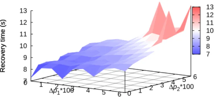
Fig. 7 and 8 show the impact of re-routing on the recovery time. The recovery time is defined as the duration of elapsed time in the simulation to recover the lost bundles due to link outage and re-routing where ∆pi (i ∈ {1, 2}) indicates
the difference in loss rate between links after and before re-routing (i.e.,∆p1= p′1− p1). The the recovery time of REC
scheme shown in Fig. 7 is significantly increased along with the higher ∆pi. Additionally, it is obvious that the recovery
may be shorter if ∆pi is negative which means that the new
path is better than the old one in terms of loss rate. Thus, we don’t show the results when ∆pi is negative. It should
be noted that, in this experiment, there are three cases where the E2E reliable communication is not met (three spikes on the top right of Fig. 7) for REC scheme when both ∆p1 and
∆p2are high. Indeed, the 100 additional bundles sent from the
Source for connection termination are not enough to recover the lost bundles due to rerouting. One needs to increase the number of information bundles (i.e., increase the simulation time) to evaluate the recovery time of these cases. The value of 13s set for these three cases is just for the sake of figure representation and explanation. In fact, 11.7s is the time the last bundle arrives at the Destination for all simulations. On the other hand, Fig. 8 shows that the recovery time of A-REC scheme is not significantly impacted when both∆p1and∆p2
increase. Indeed, the recovery time varies from 7.37s at both ∆p1= ∆p2= 0 to 7.72s when ∆p1= ∆p2= 0.06. p 1 p 2 p’ 1 p’ 2 S D R R 1 2
Fig. 6: Re-routing scenario.p1 and p2 are loss rates on path
before re-routing event whilep′
1andp′2 are loss rates on path
0 1 2 3 4 5 6 0 1 2 3 4 5 6 7 8 9 10 11 12 13 Recovery time (s) ∆p1*100 ∆p2*100 Recovery time (s) 7 8 9 10 11 12 13
Fig. 7: Recovery time of REC increases significantly when both∆p1 and∆p2 increase
0 1 2 3 4 5 6 0 1 2 3 4 5 6 7 8 9 10 11 12 13 Recovery time (s) ∆p1*100 ∆p2 *100 Recovery time (s) 7.35 7.4 7.45 7.5 7.55 7.6 7.65 7.7 7.75
Fig. 8: Recovery time of A-REC is not strongly impacted when both∆p1 and∆p2 increase
VI. CONCLUSION
In this paper, we introduced the use of an on-the-fly cod-ing scheme to enable E2E reliable communication in DTN architecture. As computation power and overhead are costly in this context, we presented simple strategies for re-encoding and acknowledgment at relay nodes to reduce the overhead in-jected into the network. Furthermore, we proposed an adaptive mechanism with low complexity to 1) reduce further the over-head, 2) deal with network dynamics while ensuring reliable communication. Lastly, we studied the impact of re-routing on the recovery time and reliability. The results showed that the proposed mechanism significantly reduces the overhead and handles well the changes in network conditions such as re-routing. For future work, we plan to study and evaluate the integration of our proposed mechanism into existing data delivery protocols such as bundle protocol and CFDP.
VII. ACKNOWLEDGMENTS
This work has been supported by French National Center for Space Studies (CNES).
REFERENCES
[1] V. Cerf, S. Burleigh, A. Hooke, L. Torgerson, R. Durst, K. Scott, K. Fall, and H. Weiss, “Delay-Tolerant Networking Architecture,” RFC 4838 (Informational), Internet Engineering Task Force, Apr. 2007. [Online]. Available: http://www.ietf.org/rfc/rfc4838.txt
[2] Y. Wang, S. Jain, M. Martonosi, and K. Fall, “Erasure-coding based routing for opportunistic networks,” in WDTN ’05: Proceedings of the 2005 ACM SIGCOMM workshop on Delay-tolerant networking. New York, NY, USA: ACM, 2005, pp. 229–236.
[3] X. Zhang, G. Neglia, J. Kurose, and D. Towsley, “On the benefits of random linear coding for unicast applications in disruption tolerant networks,” in Modeling and Optimization in Mobile, Ad Hoc and Wireless Networks, 2006 4th International Symposium on, April 2006. [4] E. Altman and F. De Pellegrini, “Forward correction and fountain codes
in delay tolerant networks,” in INFOCOM 2009,
[5] Z. Haas and T. Small, “A new networking model for biological applica-tions of ad hoc sensor networks,” Networking, IEEE/ACM Transacapplica-tions on Networking, vol. 14, no. 1, pp. 27–40, 2006.
[6] K. A. Harras and K. C. Almeroth, “Transport layer issues in delay tolerant mobile networks,” in IN IFIP NETWORKING, 2006. [7] S. Farrell and V. Cahill, “Evaluating LTP-T: A DTN-Friendly transport
protocol,” in IWSSC, Salzburg, Austria, Sep. 2007.
[8] P. Tournoux, E. Lochin, J. Leguay, and J. Lacan, “Robust streaming in delay tolerant networks,”
[9] J. Zinky, A. Caro, and G. Stein, “Random binary fec scheme for bundle protocol,” Internet Engineering Task Force, Internet Draft draft-irtf-dtnrg-zinky-random-binary-fec-scheme-00, Aug. 2012, (Work in progress).
[10] ——, “Bundle protocol erasure coding extension,” Internet Engineer-ing Task Force, Internet Draft draft-irtf-dtnrg-zinky-erasure-codEngineer-ing- draft-irtf-dtnrg-zinky-erasure-coding-extension-00, Aug. 2012, (Work in progress).
[11] K. Scott and S. Burleigh, “Bundle Protocol Specification,” RFC 5050 (Experimental), Internet Engineering Task Force, Nov. 2007. [Online]. Available: http://www.ietf.org/rfc/rfc5050.txt
[12] T. de Cola and M. Marchese, “Reliable data delivery over deep space networks: Benefits of long erasure codes over arq strategies,” Wireless Communications, IEEE, vol. 17, no. 2, pp. 57–65, 2010.
[13] T. De Cola, E. Paolini, G. Liva, and G. Calzolari, “Reliability options for data communications in the future deep-space missions,” Proceedings of the IEEE, vol. 99, no. 11, pp. 2056–2074, 2011.
[14] “CCSDS File Delivery Protocol, Recommendation for Space Data System Standards,” CCSDS 727.0-B-4, Blue Book, no. 3, 2007. [15] J. Lacan, V. Roca, J. Peltotalo, and S. Peltotalo, “Reed-Solomon Forward
Error Correction (FEC) Schemes,” RFC 5510, Apr. 2009.
[16] V. Roca, C. Neumann, and D. Furodet, “Low Density Parity Check (LDPC) Staircase and Triangle Forward Error Correction (FEC) Schemes,” RFC 5170, June 2008.
[17] J. Lacan and E. Lochin, “Rethinking reliability for long-delay networks,” in Proceedings of International Workshop on Satellite and Space Com-munications IWSSC, Oct. 2008.
[18] J. K. Sundararajan, D. Shah, and M. Medard, “ARQ for network coding,” IEEE Int. Symp. on Information Theory, pp. 1651–1655, July 2008. [19] P. Tournoux, E. Lochin, J. Lacan, A. Bouabdallah, and V. Roca,
“On-the-fly erasure coding for real-time video applications,” Multimedia, [20] E. Koutsogiannis, F. Tsapeli, and V. Tsaoussidis, “Bundle Layer
End-to-end Retransmission Mechanism,” in Baltic Congress on Future Internet Communications, Feb 2011, pp. 109–115.
[21] T. T. Thai, J. Lacan, and E. Lochin, “Joint on-the-fly network cod-ing/video quality adaptation for real-time delivery,” Signal Processing: Image Communication, vol. 29, no. 4, pp. 449 – 461, 2014.