OATAO
Open Archive Toulouse Archive Ouverte
(OATAO)
OATAO is an open access repository that collects the work of some Toulouse
researchers and makes it freely available over the web where possible.
This is
version published in:
Official URL:
To cite this version:
Any correspondence concerning this service should be sent to the repository administrator:
Dispersion of graphite flakes into boehmite sols for the preparation of
bi-layer-graphene / alumina coatings on stainless steel for tribological
applications
Karim Hentour
a,b, Viviane Turq
a, Alicia Weibel
a, Florence Ansart
a, Jean-Michel Sobrino
b,
Julien Garcia
b, Pierre-François Cardey
c, Christophe Laurent
a,⁎a CIRIMAT, Université de Toulouse, CNRS, Université Toulouse 3 Paul-Sabatier, 118, Route de Narbonne, 31062, Toulouse cedex 9, France b CETIM (Centre technique des industries mécaniques), 52, Avenue Félix Louat, CS 80067, 60304, Senlis cedex, France
c CETIM (Centre technique des industries mécaniques), 7, Rue de la Presse, CS 50802, 42952, Saint-Étienne cedex 1, France
Keywords: Graphite Graphene Alumina Composite coatings Tribology A B S T R A C T
Carbon-alumina coatings on stainless steel were prepared by a sol-gel route. The dispersion of the commercial graphite flakes by an ultrasonic bath, an ultrasonic probe and a high-shear mixer, produce thinner flakes, few-layered-graphene and bi-layer-graphene (BLG), respectively. The coatings were examined by optical and elec-tron microscopy, interferential rugosimetry, optical profilometry and Raman spectroscopy. The friction coeffi-cient against a steel ball is decreased by a factor of 5–7 and the wear volume is reduced by a factor of 6–38 compared to a pure alumina coating. The best results correspond to the sample prepared using the high-shear mixer. Delamination of the graphite flakes into BLG during the friction test provides the system with debris suitable for tribofilm building up and lubrication but it is better to already have carbon dispersed as BLG in the coating before the test, notably because the carbon surface area available is much higher.
1. Introduction
Composite coatings made up of an oxide matrix containing carbon nanotubes (CNTs) [1–3], graphite or graphene [3–7] are of particular interest for the surface protection of many bulk materials. They act as self-lubricating materials showing a high resistance to friction and wear, moreover preventing the need for liquid lubricants. Balani et al. [1] reported that the sliding wear volume loss of a plasma-sprayed 8 wt. % CNT/Al2O3coating against a ZrO2pin (dry conditions, normal load 48 N) was 49 times lower than for an Al2O3coating. Keshri et al. [2] reported a 72% increase in wear resistance against a WC ball (298 K, ball-on-disk tribometer) for a 8 wt. % CNT/Al2O3coating compared to Al2O3. Note that these results were partly attributed to indirect effects of the presence of CNTs, such as a locally enhanced densification of the surface and a higher toughness of the coating through CNTs bridging between the splats and/or Al2O3grains. Murray et al. [8] reported a two order of magnitude reduction in the specific wear rate (dry con-ditions, normal load 10 N), compared to Al2O3, for a 1 wt.% graphene nanoplatelets (GNP)/Al2O3composite prepared by thermal spraying. Li et al. [4] studied the tribological behavior of graphite/ZrO2and gra-phene/ZrO2coatings deposited by thermal spraying on a titanium alloy
substrate. The tribological tests were carried out in a ball-and-plate configuration with an Al2O3ball under a normal load of 100 N. The addition of carbon (1 wt%.) in the form of 5–20 nm-thick GNP increased the wear resistance (50%) and reduced the coefficient of friction (14%) compared to the ZrO2 coating. These results were attributed to the formation of a continuous GNP-rich amorphous tribofilm at the surface and its transfer to the ball. By contrast, the graphite/ZrO2 coatings exhibited a discontinuous carbon-rich film which improved the lu-brication but was not as protective as the GNP/ZrO2tribofilm. These authors also reported [5] that 1.5 wt% GNP/CaSiO3coatings on a ti-tanium alloy substrate showed an increased wear resistance (by a factor of 22) compared to the CaSiO3coating (ball-plane tests, stainless steel ball, normal load 10 N). This was attributed to a homogeneous dis-persion of the GNP within the matrix and to a bridging effect between the GNP and the CaSiO3grains. However, the friction coefficient for the composite coatings was slightly higher (≈ 1) than that for CaSiO3(≈ 0.9). Gómez et al. [6] prepared thermal-sprayed graphene/Y2O3-Al2O3 -SiO2(YAS) composite coatings on a SiC substrate. A decrease in wear volume (65%) and friction coefficient (35%) was reported for the coating containing 2.3% vol. of carbon in the form of GNP (≈ 50–100 nm thick) compared to the pure YAS coating (ball-plane ⁎Corresponding author.
E-mail address:laurent@chimie.ups-tlse.fr(C. Laurent).
configuration, 440-C stainless steel ball, normal load 10 N). Raman spectroscopy analyses and SEM observations of the wear track revealed the presence of a carbonaceous tribofilm composed of damaged gra-phene. A lubrication mechanism was proposed, involving a progressive exfoliation of graphene during the tribological test. Graphene/TiO2 coatings prepared by the sol-gel route on SiO2glass substrates show reduced friction and wear [7], which could result from an increased toughness and from a decrease in the TiO2grain size upon increase of the content of GNP (sheet size ∼ 5 μm, thickness 1–5 nm). Interesting wear and friction properties (pin-on-disk sliding tests) were also re-ported for graphene/MgO/Mg3(PO4)2 coatings on magnesium alloys [9]. Note that the comparison of the results reported by different groups is notably hampered because different carbon samples are used, the preparation routes markedly differ and the tribological testing condi-tions (counterface, load, contact pressure, sliding distance, relative humidity, temperature) vary widely. It is interesting to note that a re-cent review on graphene-ceramic composites [10] stressed that the influence of the graphene source on the tribological properties has rarely been explored.
Austenitic stainless steels are highly resistant to corrosion and thus are widely used in the aerospace, energy, medical and food industries. However, they often have to be protected against adhesive wear (sei-zure), which could lead to a significant loss of profitability and possibly to some environmental impact. In a previous work [3], we investigated the tribological properties against a steel ball (normal load 2 N) of carbon/Al2O3coatings on 304-L stainless steel, prepared using either commercial CNTs (average number of walls equal to 8) or commercial graphite flakes. The carbon/Al2O3 coatings present a lower friction coefficient (by a factor of 4–5) and lower wear (by a factor of 2 for graphite flakes) compared to a pure Al2O3coating. It was shown that there is no dramatic deterioration of the structure of the CNTs during the friction test whereas the graphite flakes are partially delaminated. The CNT/Al2O3coating is peeled off the substrate very early in the test, reflecting total wear, and the so-produced debris would show a lu-bricating role that pure Al2O3does not, but however less efficiently than for graphite/Al2O3coatings. In the latter case, the so-generated debris form a lubricating film, which is detected on the steel ball, suggesting that the observed lubricating effect during sliding may be at least partially related to the building up of a tribofilm on the ball and to the smearing of this film over the contact area. Some simple modeling further showed that only the outer wall of the CNTs contributes to the sliding, in agreement with the observed absence of major deterioration, and that the total available carbon surface area in the specimen is the relevant parameter, by contrast to a total carbon weight or volume. Therefore, it was shown [3] that graphite flakes are more efficient than CNTs, at least in these experimental tribological conditions, because they are readily delaminated into thinner flakes (few-layered-graphene, FLG) during the test, providing more desirable lubricating surface area. The aim of the present work is to investigate whether increasing the carbon surface area initially available in the sample, i.e. before the friction test, by suitable modifications of the experimental process would produce a further reduction of friction and wear.
2. Experimental methods
2.1. Raw materials
The substrates were austenitic stainless steel disks (AISI 304-L, diameter 30 mm, thickness 5 mm, arithmetic average height roughness (Sa) 0.4 μm). The surface of the disks was first pre-treated using alkaline degreasing, acid pickling and nitric acid passivation [11]. A boehmite powder was prepared in-house: an aqueous solution (2 mol/L) of AlCl3.6H2O (99%, ref. 237078 Sigma-Aldrich) was rapidly poured into an aqueous solution (0.4 mol/L) of NH4OH (30–32% ref. V000637 Sigma-Aldrich) under magnetic stirring at room temperature. This caused the immediate precipitation of aluminium hydroxide Al(OH)3. The so-obtained precipitate was filtered, washed with deionized water
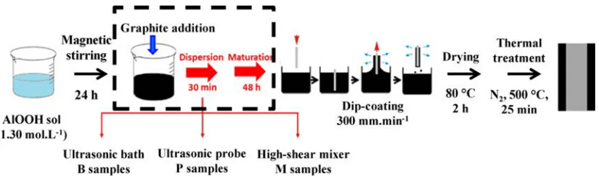
Fig. 1. Schematic representation of the preparation process of the Al2O3coating (without the steps in the dashed rectangle) and of the carbon/Al2O3coatings
(including the steps in the dashed rectangle).
Fig. 2. XRD patterns of the (a) un-coated steel substrate and (b) Al2O3-coating
and carbon/Al2O3coatings (c) B, (d) P and (e) M.
c) d)
-
c) b) a) 20.---
1
Graphite addition1
Magnetic ~f
•
_ _
9
st : : ; 1~
D
-
nM
;;
o
l
1•
JG
•
·
~.
-0
24 h1 -
30min 48h1 .
•u -
1111
AIOOHsol (1.30 mol.L·1)~
- -
1
- -
J
Oip-coating3
00
mm.min·1Ultrasonic bath Ultrasonic probe High-shear mixer
B samples P samples M samples
C (002) y-Fe
'f,.
y-Fe (200) (110) 1 ./ \,...À
I
_
~_,.J
--
·-,.
J ~ .1\..-_ j"'
J\
25 30 35 40 45 50 55 20 (degrccs) ThermalD
0rying treatment ~ ~80
°C N
2,
500
°C,
2h 25 minand oven-dried (90 °C, 24 h) where partial dehydration produced the desired boehmite (γ-AlOOH) powder. A known amount of boehmite powder was dispersed into a solution of deionized water and acetic acid producing a boehmite colloidal sol (1.3 mol.L−1). Four such batches of boehmite sol were prepared as required for the study. Graphite platelets were purchased from Abcr company, Germany. Flakes about 15 nm
thick are agglomerated into platelets about 1.5 μm in lateral dimension and thickness. The appropriate quantity calculated to produce a 19 ± 2 wt% carbon/Al2O3 coating (which was verified by electron microprobe analysis) was dispersed into three of the boehmite sols, using three different routes. For the first one, an ultrasonic bath (Si-napTec NEXUS 198) with a power of 80 W was used [3]. For the second one, an ultrasonic probe (150 W, Vibra Cell 75042 sonotrode) was immersed in the sol. The third carbon/boehmite sol was prepared using a high-shear mixer with rotor/stator geometry (Ultra-Turrax® disperser, VWR VDI 12). Rotation speed was fixed at 30000 rpm. The sols were left to maturate (48 h) in order develop the inorganic network and to reach a viscosity about 20 mPa.s, suitable for the dip-coating process and the required coating thickness. The carbon/boehmite sols will be denoted hereafter as sample B (bath), P (probe) and M (mixer) and so will the coatings derived from these.
2.2. Preparation of the coatings
The stainless steel substrates were dipped once into the boehmite or carbon/boehmite colloidal sols and withdrawn at a controlled speed (300 mm.min−1), resulting in the deposition of a sol layer onto the substrate. After removing of the excess liquid, drying in air (80 °C, 2 h) transformed the sol into a xerogel. Subsequently, a heat-treatment in N2 (500 °C, 25 min, heating rate 100 °C.h−1, natural cooling) resulted in the formation of the Al2O3and carbon/Al2O3coatings. The complete preparation process is schematized inFig. 1.
2.3. Characterization
Grazing incidence X-ray diffraction (XRD) was carried out on the substrate and on the different coatings using a Siemens D5000 dif-fractometer with Cu Kα X-ray source. XRD patterns were collected at room temperature by 0.03° (2θ) scanning steps over the 20-55° range. N2 sorption isotherms of carbon samples prepared by the ultrasonic bath, ultrasonic probe and high-shear mixer routes (without boehmite) and dried afterwards were measured at liquid-N2 temperature (Micromeritics ASAP 2020). The samples were previously degassed by heating at 120 °C under a primary vacuum for 12 h. Specific surface areas (SBET) were calculated using the BET equation. Pore size dis-tributions were evaluated from the desorption branch using the non-local density functional theory (NLDFT) kernel in the MicroActive 3.00 software. Focused ion beam microscopy (FIB, FEI HELIOS 600i) was used for the preparation of a thin lamella of the Al2O3coating, which was further thinned to electron transparency by Ga+ion-milling. The so-obtained thin slice was observed by transmission electron micro-scopy (TEM, JEOL 2100 F, 200 kV) and studied by selected area elec-tron diffraction (SAED). The coatings were examined by using field-emission-gun scanning electron microscopy (FESEM, JEOL JSM 6700 F) and interferential rugosimetry (Zygo NewView 100). The size of the carbon particles was obtained from measurements on the FESEM sur-face images by using the ImageJ software. Cross sections were prepared by cryo-fracturation on notched samples. The wear tracks were ob-served by 3D optical profilometry (SENSOFAR S neox) and optical microscopy (Keyence VHX-1000E). Selected samples were studied by Raman spectroscopy (Horiba 800 spectrometer using 633 nm laser ex-citation). The spectra shown are averages from three spectra obtained from three different areas in a given sample.
2.4. Tribological and adherence tests
Friction tests were performed using a ball-on-disk geometry in ro-tary mode (CSM Tribometer) in compliance to the ASTM G99 interna-tional standard. Tests (normal load 2 N, rotating speed 10 cm.s−1and
Fig. 3. N2sorption isotherms recorded at liquid N2temperature, showing the
adsorbed volume versus relative pressure, for the carbon prepared in conditions similar to the (a) B, (d) P and (c) M coatings, insets : enlargement of the 0.35-0.85 relative pressure range.
120
-
20 ~ 18"'
100
8
16 (,j-
~80
148
12=
ô
60
10...
0.35 0.55 0.75 "O ~40
.Q,_
0 Ill "O<
20
0
a)
0.00
0.20
0.40
0.60
0.80
.
1.00
120
-
20 Of)--
18 I')100
8
(,j 16-
~80
148
12=
ô
60
JO...
0.35 0.55 0.75 "O ~40
.Q,_
0 Ill20
"O<
0b)
0.00
0
.
20
0.40
0
.60
0.
80
1.00
120
-
Of) 45 --I')8
100
(,j 35-
~80
8
25=
ô
...
60
"O ~ .Q,_
40
0 <Il "O<
20
0c)
0.00
0.20
0.40
0.60
0.80
1
.00
Re
l
at
i
ve press
u
re (P/P
0)total sliding distance 250 m) were performed at room temperature in ambient air with a 40–60% relative humidity. The un-polished surfaces were rubbed against a 316-L steel ball 10 mm in diameter, corre-sponding to a 390 MPa calculated hertzian average contact pressure. The frictional force transferred to a load cell was recorded throughout the test. All friction tests were repeated three times, showing identical results. The adherence of selected coatings was evaluated according to the VDI 3198 standard [12]. A Rockwell C type indenter (cone) was driven on the surface of the coating by applying a maximum load of 1500 N. The samples are then observed by optical microscopy and classified into categories, as described in [12], according to the degree of cracking and delamination caused by the so-induced plastic de-formation.
3. Results and discussion
Analysis of the XRD pattern for the un-coated 304-L steel substrate (Fig. 2a) reveals the austenite (γ-Fe) (111) and (200) peaks (major phase) and a weak ferritic or martensitic (α’-Fe) peak (minor phase), in agreement with previous studies [3]. For the Al2O3-coated sample (Fig. 2b), the steel peaks are less intense and no peaks corresponding to crystallized Al2O3 are detected. For all carbon/Al2O3-coated samples (Fig. 2c, d and e), very weak steel peaks are detected in addition to a strong graphite (002) peak. There is no appreciable difference between the three samples, which could reflect that whatever the method used for the dispersion of graphite into the sol, graphite particles large en-ough to mask the XRD signal of smaller ones are still present in the samples. It has indeed been noted [13] that the low dimensionality and poor crystallinity of graphene samples in the direction perpendicular to the c-axis, cause a very low intensity of the (002) peak. Again, no peaks
corresponding to Al2O3are detected in these XRD patterns, showing that Al2O3here is either amorphous or made up of extremely small crystallites. The TEM examination of the xerogel samples (i.e. before the 500 °C heat-treatment in N2) did not reveal enough differences to successfully discriminate them. In order to get some better information on the division state of the carbon particles, the graphite particles were dispersed by the ultrasonic bath, ultrasonic probe and high-shear mixer routes, in conditions similar to those used for the B, P and M samples, respectively, but without boehmite. The N2sorption isotherms of the carbon samples are shown inFig. 3. The BET specific surface area of the samples is equal to 18, 22 and 33 m²/g for the samples prepared in conditions similar to the B, P, and M coatings, respectively. The modest values are a consequence of the agglomeration that inevitably occurred during the drying step in the absence of boehmite particles, but nevertheless the increase in specific surface area could evidence a higher division state of the carbon particles. The isotherms show a hysteresis loop at relative pressures above 0.40, although it is fairly narrow for the samples prepared in conditions similar to the B (Fig. 3a) and P (Fig. 3b) coatings. The shape of the isotherm and specifically the presence of the hysteresis loop points to a type IV isotherm, one of the six types of isotherm recognized by the IUPAC classification and char-acteristic of mesoporous adsorbents (i.e. the pore size diameter is in the range 2–50 nm) [14]. Thus, the hysteresis loop for the sample prepared in conditions similar to the M coating (Fig. 3c) clearly reveals the presence of a much high proportion of mesopores for this sample. It is widely accepted that there is a correlation between the shape of the hysteresis loop and the texture (pore size distribution, pore geometry and connectivity) of a mesoporous material [14]. The isotherm (Fig. 3c) shows the IUPAC-classification H2 loop [14] indicating materials that are often disordered, where the distribution of pore size and shape is
not well defined and also indicative of bottleneck constrictions and interconnecting mesopores. The mesopore size distributions (not shown) are very broad, reflecting mostly the inter-particle space in the specimen [15,16], although the proportion of mesopores in the range 2–10 nm, with a peak at 5 nm, is much more abundant for the sample prepared in conditions similar to the M coating. This could reflect that the high-shear mixer treatment exfoliated the graphite particles to a large degree and that subsequent agglomeration during drying pro-duced mesoporous particles. This shows that the M-like sample is sig-nificantly different from the other two (B- and P-like conditions). These results are in qualitative agreement with a study [17] reporting the high
efficiency of the high-shear mixer (used for the present M sample) for the production of high-quality graphene sheets, where the major part is less than 1 nm thick. Thus, the results at this stage support the hy-pothesis that carbon species in the M coating could be in the form of graphene sheets, bi-layer graphene (BLG) or at least FLG. More studies are warranted to better understand the dispersion and division state of the carbon particles when using the various methods reported here.
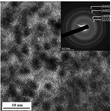
HRTEM observation of the Al2O3-coating thin slice prepared by FIB (Fig. 4) reveals crystallites about 2–4 nm in size, too small to be de-tected by XRD in our experimental conditions. The SAED pattern (inset inFig. 4) presents four rings corresponding to the (222), (400), (440) and (444) planes of γ-Al2O3, which was formed during the thermal treatment (500 °C, N2) of the boehmite-based gel.
Observation of white-light interferential rugosimetry images of the surface reveals that B (Fig. 5a) shows surface irregularities which could reflect the agglomeration of graphite particles. The surface is more uniform for P (Fig. 5b) and M (Fig. 5c), which could reflect a better dispersion of graphite. The streaks resulting from the surface grinding of the substrate are observed as vertical lines on the images. The ar-ithmetic average height roughness (Sa-Table 1) calculated from the images is equal to about 0.4 μm for both steel substrate and Al2O3 coating [3], 0.7 μm for B and 0.3 μm for P and M. The maximum height roughness (Sz-Table 1) calculated from the images is equal to 2.8 μm for the steel substrate and to 2.5 μm for the Al2O3coating, 3.0 μm for B and 2.0 μm for both P and M. These values are in good agreement with the slightly leveling effect towards steel substrate roughness of the Al2O3coating, as shown in [3]. The substrate leveling effect for P and M is higher than the one for Al2O3because their thickness (e -Table 1) is higher. B exhibits a rougher surface, which could reflect a poor dis-persion of the graphite particles, whereas P and M present a much smoother surface, reflecting an enhanced dispersion associated with the more pronounced leveling effect.
The FESEM images of the surface of the coatings are shown inFig. 6. The observations were made in backscattered electron mode (chemical composition contrast) to highlight the graphite particles (in black). The graphite particle size distributions (Fig. 4, right panel) were obtained by measuring the size of about 100 particles from several images showing different areas on the surface. The values are reported in
Table 1. For B (Fig. 6a and d), the graphite is mostly in the form of agglomerates 2–10 μm in size, i.e. larger than for the initial powder, showing a fairly poor dispersion. The average size of the graphite particles for B is equal to 3.6 μm. For P (Fig. 6b and e), the proportion of the graphite agglomerates larger than 3 μm is much lower and the most abundant population (accounting for 56%) is that in the range 1–2 μm. The average graphite size for P is equal to 1.8 μm, i.e. half the value found for B, showing that the process using the ultrasonic probe is more efficient to disperse the graphite particles than the process using the ultrasonic bath. For M (Fig. 6c and f), the proportion of graphite par-ticles below 1 μm in size is significantly higher than for P (31 vs 8%) whereas the proportion of particles in the range 2–3 μm is lower (11 vs 29%). The average graphite size for M is equal to 1.4 μm.
Cross-sections images (Fig. 7) show that the thickness of the B, P and M coatings (Table 1) is in the range 3.2–3.6 μm (it was shown to be about 1 μm for Al2O3[3]) and that the graphite particles are observed over the entire thickness of the coatings. The particles sizes are in good agreement with those observed on the surface (Fig. 6). Some porosity (arrowed inFig. 7) is observed for B and P but not for M.
Typical curves showing the friction coefficient against a steel ball versus the sliding distance are shown inFig. 8. The curve for the Al2O3 coating is very unstable, which could reflect that wear is severe, and a lot of debris is visibly generated [3]. For the B coating, there is a small but regular increase of the friction coefficient during the whole sliding distance of the test. The curves for P and M are more stable. For all
Fig. 5. White-light interferential rugosimetry images of the carbon/Al2O3
coatings: (a) B, (b) P and (c) M.
Table 1
Graphite dispersion method, coating thickness (e), arithmetic average height roughness (Sa), maximum height roughness (Sz), average graphite particle size (D), average final friction coefficient (μa), wear volume (VW).
Sample Graphite dispersion
method e(μm) S(μm)a Sz d(μm) μa V(mmw 3) Al2O3[3] – 1.0 0.4 2.5 – 0.95 0.0861 B Ultrasonic bath 3.6 0.7 3.0 3.6 0.20 0.0147 P Ultrasonic probe 3.5 0.3 2.0 1.8 0.16 0.0055 M High-shear mixer 3.2 0.3 2.0 1.4 0.14 0.0023 ' ~ . '· .. •.'· ·
.
.
• ..
~ . .. .. ·,r. , ,· J .. ~. '100
µm
JO
µm
~-
, ...:· ·. .' . •.·.~ .' ~ .. · .100
µm
-lOµm
100
µm
specimens, the average final friction coefficient (μa-Table 1) was cal-culated for the last 50 m of the tests. The Al2O3coating (μa= 0.95) does not provide any improvement on friction behavior over un-coated steel (μa= 0.80) [3], whereas μais markedly lower for the composite coat-ings, reaching a stable value of 0.20, 0.16 and 0.14 for B, P and M, respectively.
Post-test optical observations of the wear tracks of the coatings and the corresponding steel balls are presented inFig. 9. For the sake of comparison, the specimens have been observed in the area where the sliding movement is perpendicular to the substrate grinding direction. For the Al2O3-coated sample, the wear-track is about 850 μm wide [3]. The wear tracks are less wide for B, P and M (300, 210 and 190 μm, respectively) and they exhibit sliding grooves with only partial wear of the coatings. Moreover, the grinding streaks of the substrate are partly reproduced by the coated surface for the M sample, perpendicular to the wear track (Fig. 9c), indicating a milder wear for this sample. The corresponding steel balls exhibit a limited wear with a black film-like
layer and very few powder-like wear particles (Fig. 9, right panel). A tribologically-formed film (tribofilm) was formed onto the steel ball (Fig. 9, right panel), suggesting that the observed lubricating effect during sliding may be at least partially related to the building up and to the smearing of the tribofilm over the contact area.
The wear tracks were observed by non-contact optical profiler imaging (Fig. 10, left panel), and the corresponding profiles perpendi-cular to the track (Fig. 10, right panel) were used to measure the cross sectional surface corresponding to the plane wear loss (in red in
Fig. 10), subtracting the lateral material displacement (in green in
Fig. 10). The plane wear volume (Vw) was calculated for the track ra-dius and the average cross sectional surface according to Eq.(1):
=
VW(mm3) 2 Rt Sav (1)
with Rt= track radius (mm), Sav= average cross sectional surface (mm²).
Very low ball wear volumes have been evaluated and have thus Fig. 6. FESEM images of the surface of the coatings and the corresponding graphite particle size distributions: (a, d) B, (b, e) P and (c, f) M.
60
-
~50
B
Q-
;,;.-,
40
CJ30
C ~=
O"'
20
f
10
~0
<1 1
-
2 2-3 3-4 >4
d)
Size (µm)
60
-
~
50
p
Q-
;,;.-,
40
CJ30
C ~20
=
O"'
f
10
~0
<1 1-2 2-3 3-4 >4
e)
Size (µm)
60
-
~
50
M
-
...., 40
~ 30
~=
20
O"'
f
10
~0
f)
<1 1-2 2-3 3-4 >4
Size(µm)
been neglected in the total wear volume. The wear for M is milder (Figs. 9 and 10) than for B and P. The calculated plane wear volume for B (0.0147 mm3) is significantly higher than for P (0.0055 mm3) and M (0.0023 mm3) (V
w-Table 1). The latter value is 37 times lower than that (0.0861 mm²) reported earlier [3] for the Al2O3 coating. The Raman spectra outside and inside the wear tracks will be presented and discussed later in the text. A plot of the wear volume versus the average steady-state friction coefficient (Fig. 11) summarizes the results, clearly showing the decrease in both average friction coefficient and wear volume for the B, P and M samples, i.e. when the graphite particles have been dispersed into the boehmite sol in an increasingly more homo-geneous way.
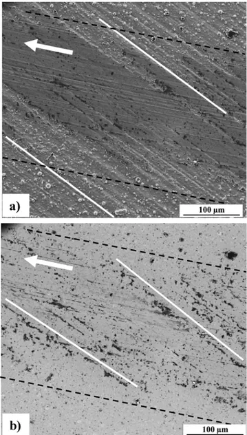
The FESEM observation recorded in secondary electron mode (to-pographic contrast) of the wear track of M (Fig. 12a) confirm the mild wear of the coating and highlight the presence of a very thin tribofilm
in the wear track (outlined by the dotted line inFig. 12a). Carbon ap-pears in black contrast on the FESEM image recorded in backscattered electron mode (chemical composition contrast) (Fig. 12b). It seems that more carbon is present inside the wear track than outside, which could reflect some delamination and releasing of the graphite flakes during the test [3], and that it is mainly found in front of the substrate grinding streaks (outlined by the solid line inFig. 12b). This suggests that the lubricating effect could be intimately linked to the building up of the tribofilm onto the counterface and to its smearing onto the whole sliding track on the coated plane.
Although a detailed investigation of the wear mechanisms as per-formed by other authors [1,2] is well beyond the scope of this work and warrants further studies, it was found of particular interest to study the wear tracks by Raman spectroscopy. Typical Raman spectra inside and outside the worn surface are shown inFig. 13. Three typical peaks were observed in all the coatings at ∼1350 cm−1(D band), ∼1585 cm−1(G band) and ∼2650 cm−1(2D band). The ratio between the intensities of the D band and the G band (ID/IG) was calculated from the spectra
(Table 2). A higher ratio is generally attributed to the presence of more structural defects (more sp3 carbon) and to a decrease in the lateral dimension of the coherent domains (crystallites) made up of sp2carbon [18]. The ID/IGratio for B (Fig. 13) increases significantly from 0.42 (outside) to 1.22 (inside), which could indicate some destruction of the graphite flakes during the friction test. The so-generated debris would form a lubricating tribofilm, lowering the shearing resistance. For P and M (Fig. 13b and 13c), the ID/IGratio similarly increases about three-fold from outside to inside the track, but both values are lower than for B. Fig. 7. FESEM images of the cross-section of the (a) B, (b) P and (c) M coatings.
Fig. 8. a) Friction coefficient against a steel ball versus the sliding distance for the Al2O3(green) and the B, P and M coatings; b) enlargement showing details for B (black), P (blue) and M (red) (For interpretation of the references to colour in this figure legend, the reader is referred to the web version of this article).
1.2
....
1.0
=
~0
.
8
-~
;;:
~ 0
.
6
u
=
0.4
0·..:
.:::!
0
.
2
-i;..0.0
a)
0.30
Pt coating....
0.25
=
~ 0 cj0.20
;;:
~ 0.15
u
§
0.10
·..:
.:::!
0.05
-i;..0.00
b)
0
0
50
IO0
150
200
Sliding distance (m)
250
B
p
M
50
100
150
200
250
Sliding distance (m)
Fig. 9. Optical images showing the wear track for the B (a), P (c), and M (e) coatings and the corresponding steel balls (b, d and f, respectively). The arrow in a) shows the sliding direction of the ball.
The I2D/IG ratio for B, P and M (Table 2) is similar for all samples outside 0.21-0.24 ± 0.02 cm−1) and inside the wear track 0.16-0.25 ± 0.02 cm−1). It is a complex contribution from the number of graphene layers, the stacking order and the defects [19,20] and precise determination requires measurements with two different excitation energies or by carefully comparing weaker combination Raman modes [20], which is outside the scope of this work. The position of the 2D band was also investigated (Table 2). Interestingly, it is progressively lower for B, P and M outside the wear track (2685, 2663 and 2654 cm-1, respectively), whereas it is constant inside the wear track (2654, 2655 and 2653 cm-1, respectively).
It was shown [19] that the Raman shift of the 2D band does not change from bulk graphite down to about 10 layers. It decreases as the number of layers decreases to 3–4 layers (FLG) and most markedly for bi-layer graphene (BLG) and ultimately graphene. Thus, it is found that the 2D band position (2654 ± 1 cm−1) inside the wear track could
correspond to that reported for BLG investigated at the same wave-length [19]. This could indicate that graphite platelets are progressively exfoliated down to BLG during the test, contributing to the formation of debris which would form a lubricating film, lowering the shearing re-sistance. These results are in agreement with those reported by Zhang et al. [21], which proposed that an ultrathin tribofilm consisting of graphene sheets formed from FLG particles during the friction test. However, as shown above, the friction coefficient and wear volume for the B, P and M coatings are not the same and we propose that this could be related to the division state of graphite in the coating before the test, in agreement with the N2sorption results presented above. Indeed, for B, prepared using an ultrasonic bath, the position of the 2D band out-side the wear track (2685 cm−1) is in line with that for bulk graphite (more than about 10 layers). Using a more powerful ultrasonic probe to disperse the graphite particle (P coating) produces more exfoliation, in agreement with the downshifted 2D band outside the wear track Fig. 10. White-light interferometry images of the wear tracks and the corresponding profiles for the (a, b) B, (c, d) P and (e, f) M coatings.
µm
a)
0.2 M M U 1.0 1.2 L, 1.6 0 .5 0b)
-10c)
O-l.7mm
'
'
'
'
1 1 1 t I t 1 1·5
...
~···
.. ···~ ...
!
... :··· ... ,: .... , ... ! ... '"
'
":"'
'
...
~... .
t 1 1 1 1 t i 1'
'
'
'
'
'10
1 1 1 1 1 1 1·
···· .. ···;· ...
r
...
r····
...
:
....
.
...
:
...
r ...r
...
B
1 1 1 1 1 1 1 1 1 1 1 1 t 1 1 1 1d)
•
1so.o
0.2
0.4
0.6
0.8
1.D12
1.4 1.61Mle)
f)
'
,
''
'
'
'
1 t 1 1 1 1 1 1·5
···-:-···~···~··
···!···:··· ···:···:···~· ...
.
f t 1 1 1 1 1 1.
'
''
'
: t 1 , 1 : 1·10
... .,
,
.
" ...
,
...
,
...
.
....
,
...
..
... , ...
,.
...
,
...
p
1 t I t 1'
''
'
''
·5
·10
M
·
15
m'TTffrrm'l'TT'l',..,.,.,.,rm-r'TTff!Tffl'TTffm-Ml'!'fflTIT'r'rrm'l'TT'l'rrml'!'ffl,,,.,,l'l'ffl'TTffrrm-0.0
0.2
0.6
o.s
1.0
12
1.4
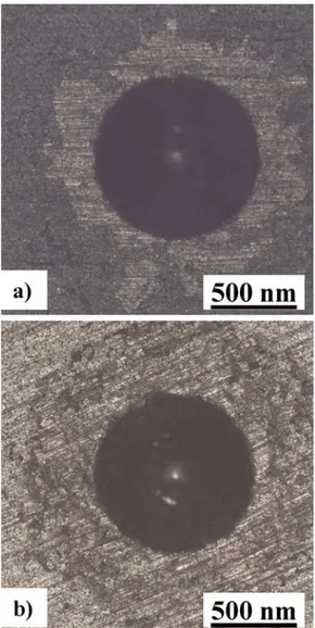
l.61M1(2663 cm−1), which could account for FLG. For the M coating, the position of the 2D band outside the wear track (2654 cm−1), as inside the wear track, could reveal that using the high-shear mixer, a method known for its efficiency for the production of high-quality graphene sheets less than 1 nm thick. [22], allowed one to obtain BLG in the boehmite sol. It is important to remember that our sample is not a film of pristine BLG and that some dispersion on the number of layers and degree of agglomeration is unavoidable. Nevertheless, the present samples could indeed be schematically regarded as graphite/Al2O3(B), FLG/Al2O3 (P) and BLG/Al2O3 (M). Some simple calculations were performed in order to evaluate the surface area developed by the carbon species in the sols and by approximation in the coatings before the friction test. Using the Raman spectroscopy results, the particle size distribution from FESEM observations (Fig. 6) and considering cylind-rical flakes and a 0.334 nm graphene layer thickness [23], the carbon surface area is found to be about 6.5 1011μm² for B, 4.0 1014μm² for P (i.e. 615 times more) and 8.0 1014 μm² for M (again twice more). Therefore, the carbon species are smaller and better dispersed and the available carbon surface area is significantly higher when using the high-shear mixer. This is highly beneficial for the tribological properties as the comparison of the friction and wear results (Fig. 11andTable 1) indeed show that the so-produced BLG (for sample M) is more efficient than FLG (for sample P) and much more than graphite (for sample B). Finally, as adhesion is an important feature of coatings, it was evaluated for the P and M coatings by the observation of the optical microscopy images of the surface (Fig. 14), after they were submitted to a Rockwell C type indenter (cone, 1500 N). A comparison to the schematic cate-gories reported in [12] reveals that both samples present significant cracking very localized on the contour of the indent but no delamina-tion, which is representative of an acceptable adhesion, although more detailed studies on the subject are warranted.
4. Conclusions
19 wt.% carbon/Al2O3coatings on 304-L stainless steel were pre-pared by the sol-gel route. Commercial graphite platelets were dis-persed into boehmite sols using three different increasingly energetic methods, involving an ultrasonic bath, an ultrasonic probe and a high-shear mixer. The coatings are about 3.5 μm thick. The friction
coefficient against a steel ball is decreased by a factor of 5–7 compared to the Al2O3coating and the wear volume is reduced by a factor of 6–38 in the present tribological conditions. The best results correspond to the sample where the graphite platelets were dispersed by the high-shear mixer. A lubricating film is observed onto the steel ball, suggesting that the observed lubricating effect during sliding may be at least partially related to the building up and to the smearing of a transferred film over the contact area. A Raman spectroscopy study inside the worn surface shows a signal consistent with BLG for all samples but interestingly, signals outside the worn surface are consistent with graphite (over 10 layers), FLG and BLG for the coatings prepared with graphite platelets dispersed by ultrasonic bath, ultrasonic probe and high-shear mixer, respectively. The higher efficiency of the high-shear mixer towards exfoliation was confirmed by the study of the N2sorption isotherms of the graphite particles dispersed by the ultrasonic bath, ultrasonic probe
Fig. 11. Wear volume versus average final friction coefficient for the Al2O3and
the B, P and M coatings. The dashed line is a guide to the eye.
Fig. 12. FESEM images of the M coating wear track; (a) topographic contrast (secondary electrons) and (b) chemical composition contrast (backscattered electrons). The limit of the wear track and the substrate grinding streaks are indicated by the dashed and solid lines, respectively. The arrows show the sliding direction of the ball.
,_
,,,
s
,§,
~s
::s0
>
...
,:,:;
0.10
0.08
0.06
0
.
04
0.02
.,..
,..
,"/
,'/
,,/
, '/ /
B •
/
p
,,
fa
,'
__
:
'
:.
~
i-
•
M '.-0.00
-+-
-"
LLC=-
~---~---~----~---i
0.00
0.20
0.40
0.60
0.80
1.00
Ave
r
age
fin
a
l fri
ct
i
o
n c
oe
ffi
c
i
e
nt
and high-shear mixer routes, in conditions similar to those used for the B, P and M samples, respectively, but without boehmite. Although some dispersion on the number of layers and degree of agglomeration is unavoidable, the present samples could indeed be schematically re-garded as graphite/Al2O3, FLG/Al2O3and BLG/Al2O3.
Thus the results show that although delamination of the graphite flakes into BLG during the test provides the system with debris suitable for lubrication, it is much more efficient to already have carbon dis-persed as BLG in the coating before the test. Simple calculations show that the carbon surface area available in the coating is then over 1200 times higher than for graphite dispersed using an ultrasonic bath. In conclusion, we propose a simple innovative method using commercial graphite and the appropriate common laboratory material to produce BLG-Al2O3 coatings with a friction coefficient against a steel ball 7 times lower and a wear volume reduced by a factor of 38 compared to the pure Al2O3coating.
Fig. 13. Typical Raman spectra outside and inside the wear track for the B, P and M coatings.
Table 2
Raman ID/IGand I2D/IGratios and 2D peak position outside and inside the wear tracks.
Sample ID/IGoutside ID/IG
inside Ioutside2D/IG Iinside2D/IG 2D (cm
−1) outside 2D (cm −1) inside B 0.42 ± 0.2 1.22 ± 0.2 0.23 ± 0.02 0.16 ± 0.02 2685 2654 P 0.23 ± 0.05 0.70 ± 0.05 0.24 ± 0.02 0.18 ± 0.02 2663 2655 M 0.26 ± 0.02 0.80 ± 0.02 0.21 ± 0.02 0.25 ± 0.02 2654 2653
Fig. 14. Optical microscopy images for the evaluation of adherence for the a) P and b) M coatings; see text for details.
G
B
--
=
ci:
' - 'è
2D
-~
C:inside
loflc
=
1.22
~...
outside
C:-a)
500
1000
1500
2000
2500
3000
G
D
p
---:--=
ci:
2D
' - '....
inside
lofl
c
=
0.70
--~
C: ~...
outside
C:-b)
500
1000
1500
2000
2500
3000
G
M
D--
=
ci:
' - '....
-"=
V, C: ~...
C:-c)
500
1000
1500
2000
2500
3000
Raman
shift (cm
·
1)[1] K. Balani, S.P. Harimkar, A. Keshri, Y. Chen, N.B. Dahotre, A. Agarwal, Multiscale wear of plasma-sprayed carbon-nanotube-reinforced aluminum oxide nanocompo-site coating, Acta Mater. 56 (2008) 5984–5994,https://doi.org/10.1016/j.actamat. 2008.08.020.
[2] A.K. Keshri, A. Agarwal, Wear behavior of plasma-sprayed carbon nanotube-re-inforced aluminum oxide coating in marine and high-temperature environments, J. Therm. Spray Technol. 20 (2011) 1217–1230, https://doi.org/10.1007/s11666-011-9669-2.
[3] K. Hentour, A. Marsal, V. Turq, A. Weibel, F. Ansart, J.-M. Sobrino, Y.M. Chen, J. Garcia, P.-F. Cardey, C. Laurent, Carbon nanotube/alumina and graphite/alu-mina composite coatings on stainless steel for tribological applications, Mater. Today Commun. 8 (2016) 118–126,https://doi.org/10.1016/j.mtcomm.2016.07. 007.
[4] H. Li, Y. Xie, K. Li, L. Huang, S. Huang, B. Zhao, X. Zheng, Microstructure and wear behavior of graphene nanosheets-reinforced zirconia coating, Ceram. Int. 40 (2014) 12821–12829,https://doi.org/10.1016/j.ceramint.2014.04.136.
[5] Y. Xie, H. Li, C. Zhang, X. Gu, X. Zheng, L. Huang, Graphene-reinforced calcium silicate coatings for load-bearing implants, Biomed. Mater. 9 (2014),https://doi. org/10.1088/1748-6041/9/2/025009025009-1 - 025009-7.
[6] A. Gómez-Gómez, A. Nistal, E. García, M.I. Osendi, M. Belmonte, P. Miranzo, The decisive role played by graphene nanoplatelets on improving the tribological per-formance of Y2O3-Al2O3-SiO2 glass coatings, Mater. Des. 112 (2016) 449–455,
https://doi.org/10.1016/j.matdes.2016.09.056.
[7] T. Bai, Y. Fang, J. Wang, Preparation and tribological properties of graphene/TiO2 ceramic films, Ceram. Int. 43 (2017) 13299–13307,https://doi.org/10.1016/j. ceramint.2017.07.028.
[8] J.W. Murray, G.A. Rance, F. Xu, T. Hussain, Alumina-graphene nanocomposite coatings fabricated by suspension high velocity oxy-fuel thermal spraying for
ultra-[9] H.N. Vatan, M. Adabi, Investigation of tribological behavior of ceramic-graphene composite coating produced by plasma electrolytic oxidation, Trans. Indian Inst. Metals 71 (2018) 1643–1652,https://doi.org/10.1007/s12666-018-1300-5. [10] P. Miranzo, M. Belmonte, M.I. Osendi, From bulk to cellular structures: a review on
ceramic/graphene filler composites, J. Eur. Ceram. Soc. 37 (2017) 3649–3672,
https://doi.org/10.1016/j.jeurceramsoc.2017.03.016.
[11] A. Marsal, F. Ansart, V. Turq, J.-P. Bonino, J.-M. Sobrino, Y.M. Chen, J. Garcia, Mechanical properties and tribological behavior of a silica or/and alumina coating prepared by sol-gel route on stainless steel, Surf. Coat. Technol. 237 (2013) 234–240,https://doi.org/10.1016/j.surfcoat.2013.06.037.
[12] N. Vidakis, A. Antoniadis, N. Bilalis, The VDI 3198 indentation test evaluation of a reliable qualitative control for layered compounds, J. Mater. Process. Technol. 143-144 (2003) 481–485,https://doi.org/10.1016/S0924-0136(03)00300-5. [13] A.R. Kamali, J. Feighan, D.J. Fray, Towards large scale preparation of graphene in
molten salts and its use in the fabrication of highly toughened alumina ceramics, Faraday Discuss. 190 (2016) 451–470,https://doi.org/10.1039/c6fd00005c. [14] K.S.W. Sing, D.H. Everett, R.A.W. Haul, L. Moscou, R.A. Pierotti, J. Rouquerol,
T. Siemieniewska, Reporting physisorption data for gas/solid systems with special reference to the determination of surface area and porosity, Pure Appl. Chem. 7 (1985) 603–619,https://doi.org/10.1002/9783527610044.hetcat0065. [15] Ch Laurent, G. Chevallier, A. Weibel, A. Peigney, C. Estournès, Spark plasma
sin-tering of double-walled carbon nanotubes, Carbon 46 (2008) 1812–1816,https:// doi.org/10.1016/j.carbon.2008.08.020.
[16] D.J. Babu, M. Lange, G. Cherkashinin, A. Issanin, R. Staudt, J.J. Schneider, Gas adsorption studies of CO2 and N2 in spatially aligned double-walled carbon na-notube arrays, Carbon 61 (2013) 616–623,https://doi.org/10.1016/j.carbon.2013. 05.045.
[17] L. Liu, Z. Shen, M. Yi, X. Zhang, S. Ma, Green, rapid and size-controlled production of high-quality graphene sheets by hydrodynamic forces, RSC Adv. 4 (2014) 36464,
https://doi.org/10.1039/c4ra05635c.
[18] F. Tuinstra, J.L. Koenig, Raman spectrum of graphite, J. Chem. Phys. 53 (1970) 1126–1130,https://doi.org/10.1063/1.1674108.
[19] A.C. Ferrari, J.C. Meyer, V. Scardaci, C. Casiraghi, M. Lazzeri, F. Mauri, et al., Raman spectrum of graphene and graphene layers, Phys. Rev. Lett. 97 (2006) 187401,, ,https://doi.org/10.1103/PhysRevLett.97.187401.
[20] T.A. Nguyen, J.-U. Lee, De Yoon, H. Cheong, Excitation energy dependent Raman signatures of ABA- and ABC-stacked few-layer graphene, Sci. Rep. 4 (2014),https:// doi.org/10.1038/srep046304630-1 - 4630-5.
[21] C. Zhang, A. Nieto, A. Agarwal, Ultrathin graphene tribofilm formation during wear of Al2O3-graphene nanoplatelet composites, 5 (2016).https://doi.org/10.1680/ jnaen.15.00027.
[22] L. Liu, Z. Shen, M. Yi, X. Zhang, S. Ma, Green, rapid and size-controlled production of high-quality graphene sheets by hydrodynamic forces, RSC Adv. 4 (2014) 36464,
https://doi.org/10.1039/C4RA06429A.
[23] Z.H. Ni, H.M. Wang, J. Kasim, H.M. Fan, T. Yu, Y.H. Wu, Y.P. Feng, Z.X. Shen, Graphene thickness determination using reflection and contrast spectroscopy, Nano Lett. 7 (2007) 2758–2763,https://doi.org/10.1021/nl071254m.
Declarations of interest
None.
Acknowledgements
This work was performed within the framework of CETIMAT, a joint laboratory between CETIM and CIRIMAT. K. Hentour thanks CETIM for the doctoral thesis grants. The authors thank M.-C. Barthélémy for as-sistance in N2 sorption experiments and Dr. Ph. De Parseval, Dr. C. Josse and Dr. S. Duluard, for assistance in the electron microprobe analyses, FESEM and TEM observations, respectively, which were per-formed at the Centre de microcaractérisation Raimond Castaing - UMS 3623, Toulouse.
References
low-wear, J. Eur. Ceram. Soc. 38 (2018) 1819–1828, https://doi.org/10.1016/j. jeurceramsoc.2017.10.022.