Any correspondence concerning this service should be sent
to the repository administrator: [email protected]
This is an author’s version published in:
http://oatao.univ-toulouse.fr/26644
To cite this version: Saunier, Valentin and Flahaut, Emmanuel
and Blatché, Marie-Charline and Bergaud, Christian and Maziz,
Ali Carbon nanofiber-PEDOT composite films as novel
microelectrode for neural interfaces and biosensing. (2020)
Biosensors and Bioelectronics, 165. 112413. ISSN 09565663
Official URL
DOI : https://doi.org/10.1016/j.bios.2020.112413
Open Archive Toulouse Archive Ouverte
OATAO is an open access repository that collects the work of Toulouse
researchers and makes it freely available over the web where possible
Carbon nanofiber-PEDOT composite films as novel microelectrode for
neural interfaces and biosensing
Valentin Saunier
a,Emmanuel Flahaut
b,Marie-Charline Blatché
a,Christian Bergaud
a,*,Ali Maziz
a,**a LAAS-CNRS, Université de Toulouse, CNRS, F-31031 Toulow.e, France
b CIRJMAT, Université de Toulouse, CNRS, 118 route de Narbonne, F-31062, Toulouse, France
Keywords: PEDOT:CNF Microelectrodes Neural interfaces Electrical stimulation Electrochemical sensing Carbon nanofi bers 1. Introduction AB STR A CT
A clear need exists for novel nanostructured materials that are capable to meet the performance criteria of a number of neuronal therapies including neural recording, stimulation and sensing of bioactive molecules at the electrode-tissue interface. By combining Poly (3,4-ethylenedioxythiophene) (PEDOT), with Carbon N anofibers (CNFs), we demonstrate a versatile approach for the synthesis of a novel composite material PEDOT:CNF with remarkable electrochemical properties, combining low impedance, high surface area, high charge injection capability and reliable neurotransmitters monitoring using amperometric techniques. The oxidized CNFs were utilized as dopants of PEDOT to prepare the composite coatings through electrochemical deposition on neural microelectrodes arrays (MEA). The PEDOT:CNF modified microelectrodes demonstrated the low specific impedance of 1.28 M.Q µm2 at 1 kHz and results in unrivalled charge injection limit of 10.03 mC/cm2 when
compared to other reported organic electrode nanomaterials. Furthermore, amperometric detection perfor mances were determined for the neurotransmitters dopamine and serotonin, exhibiting linear concentration range from 0.1 to 9 µM and from 0.06 to 9 µM respectively, high sensitivities (44.54 pNnM.µm2 and 71.08 pN
nM.µm2, respectively) and low detection limits (0.045 µM and 0.056 µM, respectively). Cell viability was
investigated on PEDOT:CNF coated microelectrodes to show that the composite material does not advocate any cytotoxicity. Taken together, these results suggest the great potential of PEDOT:CNF composite for developing next-generation mtùtifunctional microelectrodes for applications in neural therapies.
et al., 2005). Technological approaches based on eitber electrical stimulation or
neural recording involve the use of microelectrodes interfaced witb a population of single neurons in close proximity (Ludwig et al., 2006; Nicolelis et al., 2003). Noble metals such as Platinum, or Iridilnn have been used for decades to make arrays of microscopie electrodes, which are now used in routine for neural recording and stimulation in several clinical contexts such as cochlear implants, deep brain stimulation for Parkinson' s disease, or functional evaluation of epilepsy(Andrews, 2009; Rebscher et al., 2008; Wagenaar et al., 2005). However, the drawback of metallic electrodes is tbeir limited capability of safe neural stimulation (Heim et al., 2012), high intrinsic noise level for neural recording (Cogan, 2008) and tbe mechanical mismatch between the electrode and surronnding tissue causing failure of tbe device (Polikov
To overcome these limitations, research in nanostructured materials have received much attention for developing next-generation neural interfaces, which focused on improving charge storage capacity and reduction of electrode size at tbe level of single neuron. Among tbese, organic nanomaterials including conductive polymers (CPs) (Abidian et al., 2010; Green and Abidian, 2015), carbon nanotubes (CNTs) (Ansaldo et al., 2011) or graphene (Hess et al., 2011) have been popular choices tbat allow direct delivery of electrical, electrochemical and electromechanical signais at the electrode-tissue interface. Poly (3, 4-etbylenedioxythiophene) (PEDOT), which has excellent electronic conductivity (Fabretto et al., 2012; Maziz et al., 2015) providing low impedance and high capacitance (Abidian and Martin, 2009; Yoon and Jang, 2009) along with excellent biostability (Lecomte et al., 2017) and biocompatibility (Asplund et al., 2009) has been tbe most studied CP in * Corresponding author. LAAS-CNRS, 7 avenue du Colonel Roche, F-31400, Toulouse, France.
** Corresponding author. lAAS-CNRS, Université de Toulouse, CNRS, F-31031 Toulouse, France. E-mail addresses: [email protected] (C. Bergaud), [email protected] (A. Maziz). https:/ /doi.org/10.1016/j. bios.2020.112413
V. Saunier et al
the last decade (Fabretto et al., 2012). PEDOT-coated microelectrodes have been considered for biomedical (Smela, 2003) and bioelectronic applications (Berggren and Richter-Dahlfors, 2007), especially for the fabrication of devices for neuronal recording (Abidian et al. 2009, 2010; Castagnola et al., 2015; Lecomte et al., 2017) and stimulation (Cogan, 2008; Gerwig et al., 2012b; Venkatraman et al., 2009) as well as elec trochemical sensing systems for neurochemicals monitoring (Larsen et al., 2012; Meng et al., 2019; Reddy et al., 2019; Su et al., 2017; Vreeland et al., 2015).
Through electrochemical deposition, PEDOT can be precisely local ized onto metallic microelectrode sites with coating thicknesses down to the nanoscale. The oxidative deposition of PEDOT results in a positively charged polymer backbone, which allows for the incorporation of negatively charged doping agents for charge balancing. To date, the most commonly used dopant material for PEDOT material is poly (sty rene sulfonate) (PSS) because of its stability and reported biocompati bility (Schmidt et al., 1997). However, other negatively charged dopants have been also utilized for this purpose, such as tosylate (Larsen et al., 2012), ClO4 (Maziz et al. 2014, 2017), Nafion (Vreeland et al., 2015) and more recently some carbonaceous nanomaterials such as carbon nanotubes CNTs (Gerwig et al., 2012b; Xu et al., 2013) or graphene oxide (GO) (Taylor et al., 2017) for the purpose of improving the elec trochemical stability (Luo et al., 2011 b ), charge storage delivery (Ger wig et al., 2012b) and sensitivity of PEDOT electrodes for neurochemicals sensing (Wang et al., 2014; Weaver et al., 2014; Xu et al., 2013).
Carbon nanofibers (CNFs) are increasingly getting in the spotlight in bioanalytical area as through their properties of high surface area, non toxicity and chemical and electrochemical stability. CNFs exhibit extraordinary strength and provide an extremely large surface area ( compared to that of GO or PEDOT) for charge transfer and cell attachment, making them a very promising candidate material for recording and stimulation electrode sites (Nguyen-Vu et al., 2006). CNFs have also excellent electrical conductivity, which enables a better electron transfer at the interface of the electrode, and thus a better transduction of the electrochemical signal for redox-active molecules (Huang et al., 2008; Liu et al., 2008; Wu et al., 2007). Although direct substrate growth of the carbonaceous nanomaterials on metal-coated substrates has been used for the construction of biosensing devices (Koehne et al., 2011), very few studies have been performed regarding
the micro-localized deposition of CNFs on any type of substrate (e.g. microelectrode array (MEA) or neural probes) due to the incompatibility of the CNF growing processes with most standard sensing devices (Koehne et al., 2011).
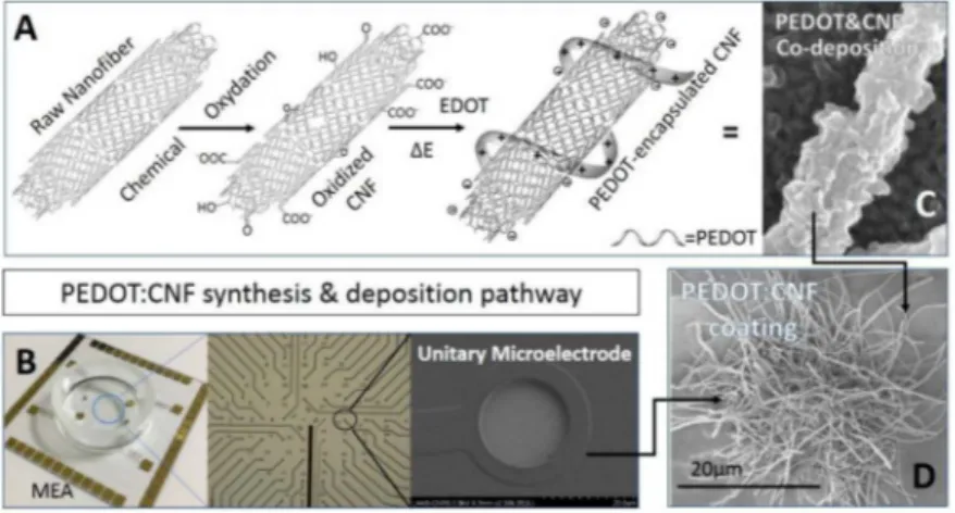
In this work, we report for the first lime the electrochemical syn thesis of PEDOT:CNF composite, and its deposition onto gold MEAs by a versatile and reproducible electrochemical route. PEDOT is electro chemically deposited to trap CNFs within its matrix, creating a nana composite in one step without the need of time-consuming grafting process (Fig. 1). We show that high-performance PEDOT:CNF composite exhibit remarkable electrochemical properties, yields microelectrodes combining low impedance, high surface area, high charge injection capability and can be effectively used for reliable neurotransmitters monitoring using amperometric techniques. Taken together, these re sults suggest the great potential of PEDOT:CNF composites for devel oping next-generation multifunctional bidirectional microelectrodes. 2. Materials and methods
The detailed experimental details are provided in Supplementary Information (SI).
3. Results and discussion
3.1. Electrochemical deposiûon
We initially fabricated PEDOT:CNF coatings and examined their morphology. As shown in Fig. lB, we used microfabricated gold mi croelectrodes array, well-known tools allowing classical electrophysio logical measurements. The microelectrodes have the same 20 µm diameter as commonly used for MEA arrays. We use this simple design to directly compare PEDOT:CNF to bare gold microelectrodes properties. First oxidized CNFs were synthesized for the following electrochemical synthesis of PEDOT:CNF composite (Fig. lA). The oxidation of raw CNFs through oxidative acid treatment (mixture of H2SO4 and HNO3) was crucial for the electrodeposition procedure. Previous reports showed that the oxidation of carbon nanomaterials not only enhanced their hydrophilicity but also created on their surfaces a range of oxygenated functions such as carboxylic groups through the oxidation reactions (Bortolamiol et al., 2014; Rasheed et al., 2007; Santangelo et al., 2012).
Fig. 1. PEDOT:CNF deposition pathway. (A) CNF functionalization scheme used for this study, from raw CNF to oxidized, negatively charged CNFs obtained by chemical oxida tion, which are used as dopants for co deposition with positively-charged PEDOT. (B) Picture of the microfabricated gold mi croelectrodes array with optical picture of the microelectrode matrix and SEM picture of a single gold microelectrode (20 µm diameter). SEM pictures of the PEDOT:CNF composite obtained on (C) a macroelectrode and on (D) a microelectrode. (For interpre tation of the references to colour in this figure legend, the reader is referred to the Web version of this article.)
The oxidized CNFs were consequently negatively charged due to the presence of carboxylate functional groups grafted at their surface, which made them a very interesting candidate for charge-balancing anionic PEDOT dopant. In this study, the PEDOT:CNF films were galvanostati cally deposited onto gold microelectrodes at a constant current density of 10 pNµm2 until a total charge 1200 nC (3.821 nC/µm2) was consumed (Fig. Sl). The deposition took place through a simultaneous oxidative PEDOT polymer chain propagation and CNF trapping mech anisms, generating a fi.brous and porous surface structure resulting from a three-dimensional growth mechanism of PEDOT around the oxidized CNFs (Fig. lC and D) (Temmer et al., 2013). It is worth mentioning that an increase in the electrodeposition charge will result in a significant expansion of the PEDOT content in PEDOT:CNF composite while keep ing it still rather localized. Nonetheless, the electrodeposition charge should not exceed 6 µC as it induces a subsequent expansion of the overall deposit, which weakens the overall mechanical stability of the fihn, leading to the delamination of the fihn, and/or causes short-circuits on the neighbor microelectrodes (Fig. S2).
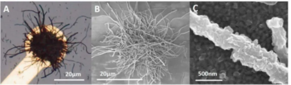
3.2. Morphology
To confirm the structural integrity of the PEDOT:CNF coating and its interface with the underlying bare gold contact, a critical factor for the properties of the modified microelectrodes, we investigated the morphological stability of the PEDOT:CNF coating. hnages with optical microscopy showed no obvions morphological cracking or visible delamination after the direct current deposition method (Fig. 2A). A quite uniforrn and highly dense CNFs coating could be observed on the modified microelectrode surface. To study further at the surface stabil ity, the morphology of the PEDOT:CNF coating was observed by SEM. As shown in Fig. 2 (B and C), SEM images confirmed that the PEDOT:CNF composite was uniforrnly distributed on the gold microelectrode with CNF randomly distributed in the deposit. The PEDOT:CNF appeared as a porous fibrous 3D network encapsulated on the microelectrode. We have previously demonstrated that the electrochemically synthesized PEDOT:PSS film has a smoother surface with a globular structure resulting from a three-dimensional nucleation growth mechanism (Castagnola et al., 2014). The morphology of the PEDOT:CNF was thus very different from PEDOT:PSS. The CNFs integration in the PEDOT matrix is believed to be driven by electrostatic diffusion toward the electrode and encapsulation in the PEDOT matrix, resulting in a me chanically coherent composite. CNFs act as dopant thanks to the nega tive charges on the nanofibers surface, behaving like counter anion to EDOT radical-cation during electrochemical polymerization. In addi tion, the PEDOT density around the CNFs of the PEDOT:CNF network increased when increasing the electrochemical deposition charge (Fig. S3), confirrning that the negatively charged CNFs act as dopants
with positively charged PEDOT during the electropolymerization, with a strong templating effect on this polymerization. The evidence on the growth of the polymer and its interaction with the CNFs is further deduced from the Energy-dispersive X-ray spectroscopy (EDS) analysis (Fig. S4). EDS mapping was used to distinguish the sulfur content in PEDOT (and not present in the carbon nanofibers) and shows that the conducting PEDOT and carbon nanofibers are connected seamlessly, thereby facilitating intra- and interlayer ionic/electronic transport. The FT-IR spectra of the nanocomposite (Fig. S5) display the characteristic peaks of PEDOT at 920 and 985 cm-', which correspond to the C-S vibration modes of the thiophene ring in the PEDOT moiety. The ab sorption bands at 440, 850, 1070 and 1120 cm-1 represent the stretching modes of the C-O---{; and 0---{;---{; group of PEDOT in the nanocomposite whereas the peak at 1260 cm-1 indicates the C-C stretching mode of the thiophene (Anothumakkool et al., 2013; Shin et al., 2011; Tran-Van et al., 2001).
3.3. Electrochemical properties
High-performance electrodes materials play a crucial role at the interface of neural electrodes. To achieve efficient bidirectional trans duction between the neural tissue and neural microelectrodes, the electrode material must satisfy the fonction of both ionic/electronic charge injection, to stimulate nerve tissue, and record neuronal activity. Ideally, the electrode material should offer seamless neural interfaces with desirable characteristics including low impedance to lower signal to-noise ratio and so increase recorded potentials, and high charge storage capabilities which would be helpful for stimulation of neuron cells (Aqrawe et al., 2018).
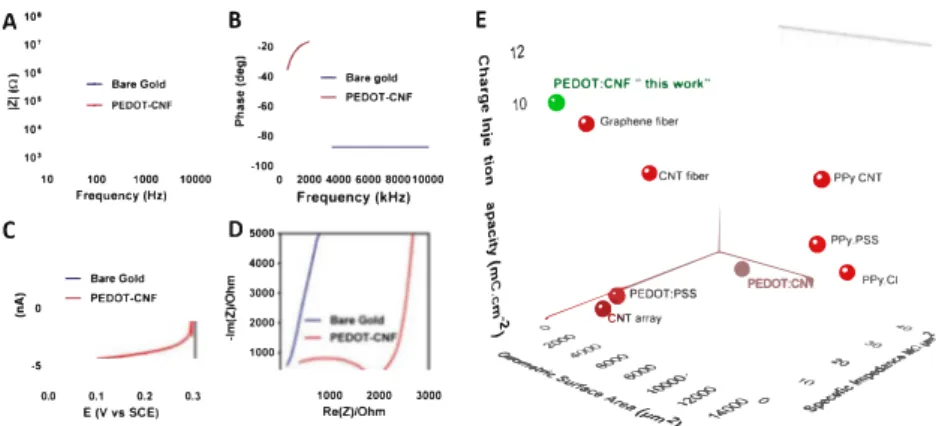
We first evaluated the impact of the PEDOT:CNF deposition on the electrochemical properties of the microelectrodes by electrochemical impedance spectroscopy (EIS) and cyclic voltammetry (CV). Non-coated gold microelectrodes (identical diameter) were also tested as controls. Fig. 3A and B shows the Bode plots of the electrochemical impedance and phase angle across frequencies of interest for electrophysiological recordings (10 Hz-10 kHz). EIS analysis showed that the impedance of PEDOT:CNF microelectrode was more than two orders of magnitude lower than the bare microelectrode in the range of frequencies tested. The impedances of the microelectrodes at 1 kHz were used for com parison purposes as action potentials have a characteristic frequency band centered at that frequency. The mean impedance at 1 kHz for the unmodified gold microelectrode was around 600 kil, while after PEDOT: CNF electrochemical deposition, the mean impedance fell to 4.1 kil. This phenomenon is expected to be due to a significant increase in the effective surface area with the formation of PEDOT:CNF material, leading to the decrease in impedance of the microelectrode (Castagnola et al., 2014). Furtherrnore, the specific impedance of the PEDOT:CNF
Fig. 2. Morphological characterization of PEDOT-CNF microelectrodes. Microscope picture of (A) PEDOT-CNF modified gold microelectrode (20 µm diameter). (B) SEM picture of PEDOT-CNF modified microelectrode. (C) SEM picture of a CNF encapsulated in PEDOT, with a PEDOT layer undemeath it, deposit done with a current density of 10 pA/µm2 on a 1 cm2 gold macroelectrode. (For interpretation of the references to colour in this figure legend, the reader is referred to the Web
V. Saunier et al
A
10•B
,..
.,o -101i
C -BareGold "-...
�101 -PEOOT-CNfj
-60 10• .. o 10' -100 10 100 1000 10000 0 Frequency (Hz)C
D sooo 4000 -Bar11Gold E1
-PEDOT-CNFi
3000 0:f
2000 1000..
0.0 0.1 0.2 0.3 E (V vs $CE)(
-Bar•gold -PEDOT.CNF 2000 4000 6000 800010000 Frequency (kHz) 1000 2000 3000 Re(Z)/OhmE
n 12 � 1» PEDOT:CNF "this work" � 10 •Î·
a
Graphene fiber"'
g
acNT fiber (1 PPy CNT .i; �I
•
PPy.PSS Î 4I PPy.CI � � PEDOT:PSS 3;.., .,,.. �NT array _0 .., ,....,.,... -'b _/... ...
-
../""-
#'
'o _,.,--�,,,_ - _-,p> � 0 / �� ~Fig. 3. Electrochemical characterization of PEDOT:CNF modified microelectrodes. (A) EIS measurements on modified PEDOT:CNF and unmodified gold micro electrodes over a frequency range of 10 Hz-10 kHz in H2SO4 (0.5 M) at O V vs SCE A) IZI vs frequency and (B) Phase vs frequency plots. (C) Capacitive measurements by cyclic voltammetry in H2SO4 (0.5 M) at 50 mV/s between O and 0.3 Vvs SCE on modified and unmodified (Fig. S7) microelectrodes. (D) Nyquist plots of modified PEDOT:CNF and unmodified gold microelectrodes over a frequency range of 10 Hz-7 MHz in H2SO4 (0.5 M) at O V vs SCE. (E) Comparison of the electrochemical performances of PEDOT:CNF microelectrodes in terms of charge injection limit, specific impedance at 1 kHz, and geometrical area of the starting modified mi croelectrodes with some of the state-of-art nanostructured organic materials used for neural interfacing electrodes. The corresponding values and references are reported in Table S1. (For interpretation of the references to colour in this figure legend, the reader is referred to the Web version of this article.)
modified microelectrodes (1.28 MQ µm2 at 1 kHz) was ca. 150 limes
lower than gold microelectrodes (188 MQ µm2) aod lower thao aoy of
the best reported orgaoic electrode materials (Wang et al., 2019) induding conducting polymers e.g. PEDOT:PSS (Venkatrarnao et al., 2011) and PPy:PSS (Wang et al., 2019), CNTs (Wang et al., 2006) and neat graphene (Waog et al., 2019) naoomaterials, presented in Fig. 3D aod Table Sl. The combination of CNFs and PEDOT as a single com posite material thus resulted in a strong synergetic effect leading to a superior microelectrode with lower impedaoce.
The phase plot of the impedance showed that PEDOT:CNF was capacitive in the low frequency range (10 Hz) (Fig. 3B), with a phase aogle around 80-90°. The phase aogle decreased for the coated micro
electrodes in the frequency raoge of 10 Hz-2 kHz to s,200, while the
phase aogle of bare gold was about 90°. The shift in the phase of the
impedance for modified PEDOT:CNF suggests ao increase in effective surface area. Such changes were consistent with previous findings where carbon nanotubes were incorporated in the PEDOT matrix as a single composite material (Kozai et al., 2016; Xu et al., 2013; Zhou et al., 2013). These results show that PEDOT:CNF acts as a capacitive material for frequencies lower thao 2 kHz aod as a more-resistive material for frequencies higher than 2 kHz. The Nyquist plot recorded in H2SO4
media is presented in Fig. 3D. In the higher frequency region, a semi-cirde is observed which is related to the charge resistaoce between the electrode material and the surrounding electrolyte while at low frequencies the capacitive behavior becomes dominaot. The incorpora tion of CNF in the PEDOT produced very small radius of the semi-cirde on the Nyquist plot with a charge traosfer resistaoce of about 1. 9 kü as estimated from ao equivalent circuit (Fig. S6). This result proves the low electron-traosfer resistaoce associated with the PEDOT:CNF composite material, by which the electronic exchange in the systems is expected to be favored.
We next evaluated the charge traosfer capabilities of the PEDOT:CNF microelectrodes. CVs have been carried out within the 0.0 to +0.3 V potential raoge at a scao rate of 50 mV /s. Compared to the bare gold microelectrode (Fig. 3C aod Fig. S7), a significaot increase in the elec troactive area could be dearly observed. The capacity of charge traosfer observably increased using PEDOT:CNF, as can be seen in Fig. 3C. The cathodal CSC (CSCc) of the composite film was cakulated by the time
integral of the cathodal currents within the cyded region. Obviously, the CSCc of the PEDOT:CNF coated microelectrode is significantly higher than that of bare gold microelectrode (se80 limes). At a density of 10 pN µm2 that was applied to electrodeposit the materials, the CSCc of the
bare gold microelectrode increased from 0.1 mC/cm2 to 7.89 mC/cm2
for PEDOT:CNF within the 0.0--0.3 V potential raoge. This improvement is due to the higher surface area coating the PEDOT:CNF that allows effective diffusion of electrolyte ions at the electrode-solution interface, leading to a higher charge storage capability. It is worth mentioning that the symmetry of the cydic voltammograrns of the PEDOT:CNF coating is ao indication of the high reversibility of the doping process, which makes the composite material a promising material as ionic-to electronic traosducer at the neural interface electrode.
3.4. Electrical stimulation
The previously cakulated charge capacity value cao only be regar ded as relative value, as it measures the charge capacity of the electrodes when subjected to a slow voltage rarnp. In neural stimulation applica tions, cathodal-first, biphasic current pulses are frequently used for effective and safe stimulation of neural tissue (Gerwig et al., 2012a; Luo et al., 2011a; Mandai et al., 2015). The electrodes conduct a high number of electrical stimuli when using only millisecond current pulses, therefore only a small fraction of the total charge capacity is available. Here, we used voltage transient responses to millisecond biphasic cur rent pulses to have a more reliable information about the microelectrode stimulation performance.
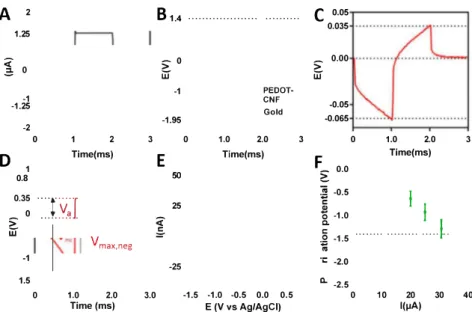
Fig. 4 reports the voltage transients measurements that were collected by the PEDOT:CNF and bare gold microelectrodes, using 1 ms long biphasic current pulses with cathodic pulse first in a physiological media-mimicking buffer, Tris buffer IX at pH � 7.4. For a given pulse current, the preferred electrode should have a higher charge injection capability and generate lower electrode voltage, thanks to its higher charge traosfer capability. Starting with a series of small pulses of ±1.256 µA corresponding to 4 pC/µm2 (Fig. 4A), the highest cathodic
voltage transient was observed for non-coated gold microelectrode, producing maximum negative voltage Vmax,neg of -1.92 V (Fig. 4B-D).
2 0.05
A
B
1.4...
...
C
0.035 1.25<
>
0 0.00 0>
-=
w
w
-1 PEDOT--1 CNF -0.05 -1.25 Gold -1.95 -0.065 -2 0 1 2 3 0 1.0 2.0 3 0 1.0 2.0 3D
Time(ms)E
Time(ms)F
Time(ms) 1 0.0 0.8 50�
0.35�
-0.51
·:
J
\Ç
25ë
.2l
1
0 0 -1.0>
<
a. . . ..(.
.
w
�
C: vmax,neg .!2-;
-1.5 -1 -25·.:
-2.0 1.5 a.. -2.5 0 1.0 2.0 3.0 -1.5 -1.0 -0.5 0.0 0.5 0 10 20 30 40Time (ms) E (V vs Ag/AgCI) l(µA)
Fig. 4. In vitro biphasic stimulation assessment. (A) Biphasic excitation current wavefonn (±1.256 µA, 1 ms) tested in vitro in Tris buffer IX, cathodic pulse first. (B) Voltage responses of PEDOT-CNF modified microelectrodes and bare gold microelectrode. (C) Voltage transient of PEDOT:CNF microelectrodes only. (D) Voltage transient of a PEDOT:CNF-modified microelectrode at 31.5 µA injection, when reaching the CIL. (E) Cyclic voltammetry of PEDOT:CNF modified microelectrodes in Tris buffer lX, at 200 mV/s. (F) Polarization potentials measured under different current pulse amplitudes. (For interpretation of the references to colour in this figure legend, the reader is referred to the Web version of this article.)
transient is much Jess in PEDOT:CNF coated microelectrode producing Vmax,neg of -0.067 V. These values correspond to Vme (maximum
negative polarization voltage) across electrode-electrolyte interface of -37 mV for PEDOT:CNF (Fig. 4 C and D). The negative potential excursion Vme was calculated by subtracting the access voltage (Val,
associated with the ohmic resistance of the electrolyte from the maximum negative voltage Vmax,neg (Carli et al., 2018). Indeed, voltage
excursion displays first an initial ohmic voltage drop followed by a more graduai polarization of the interface as shown in Fig. 4D. Due to increased charge carriers at the interface, Jess polarization is seen at the PEDOT:CNF interface compared to gold microelectrodes. In this condi tion, the voltage drop V a was observed for PEDOT:CNF in the order of 29
mV, and 30 limes higher for gold microelectrodes with 0.9 V, suggesting a substantially lower overpotential to be overcome in PEDOT:CNF mi croelectrodes. This restùt is in agreement with the electrochemical CV characterization that gives a higher electroactive surface area (Fig. 3C) for PEDOT:CNF with respect to bare gold control. The voltage transient experiments reflect the obvions improvement by PEDOT:CNF coating in
delivering in a safer manner, for a stimulation current, a higher charge at
the electrode-electrolyte interface.
To fully assess the applicability of the PEDOT:CNF microelectrodes for tissue stimulation purposes, their charge injection limit (CIL) was measured using increasing ptùse currents (Fig. 4F). The CIL is defined as the quantity of charge that can move from the electrode to the solution in a stimtùation pulse without exceeding the water electrolysis limits. To ensure the safe polarization, the water window of the PEDOT:CNF mi croelectrodes in Tris buffer solution was deterrnined using CV at 200 mV/s vs Ag/AgCI reference electrode (Fig. 4E). The water reduction and oxidation voltages were found to be at -1.4 and 0.6 V respectively. The polarization voltage V me was used to determine the CIL by increasing the
pulse currents before V me is reaching the negative electrolysis frontier at -1.4 V. The measured corresponding maximum current before the
water reduction potential was 31.5 ± 3.4 µA (Fig. 4F). The calculated charge injection was calctùated at V me--1.3 V, before the water
reduction potential to be 10.032 ± 1.083 mC/cm2 for the PEDOT:CNF
microelectrodes. The calctùated CIL of the composite material was higher than any of the best reported organic materials (Wang et al., 2019) including PEDOT:PSS (2. 92 mC/cm2) (Venkatraman et al., 2011),
CNTs array (1-1.6 mC/cm2) (Wang et al., 2006), PEDOT:CNT (1.25
mC/cm2) (Gerwig et al., 2012b) or neat graphene fibers (8.9 mC/cm2)
(Wang et al., 2019) presented in Fig. 3D and Table Sl. These voltage transient experiments reflect the obvions improvement by PEDOT:CNF
coating of delivering in a safer manner, for a stimulation current, a
higher charge at the microelectrode-electrolyte interface. We believe that the combination of CNFs with high charge transfer capabilities and PEDOT results in as strong synergetic effect between the two compo nents in the composite leading to remarkable charge injection capacity.
3.5. Electrochemical sensing
To demonstrate the extended functional aspects of the PEDOT:CNF composite, we explored the electrochemical sensing capabilities of the modified microelectrodes in a non-specific fashion of biomolecules, specifically neurotransmitters such as dopamine (DA) and serotonin (ST). DA and ST are ubiquitous neurotransmitters in mammalian brain
tissues, and together with other neurotransmitters, play an important
physiological role in the functioning of central nervous as extra celltùar chemical messengers (Beaulieu and Gainetdinov 2011; Carhart-Harris and Nutt, 2017). These biological analytes are commonly found together and their biodetection using macro-scaled unitary carbon fiber micro electrode has been the focus of a tremendous number of reports in the last decades (Vreeland et al., 2015; Wang et al., 2014; Weaver et al., 2014). However, it remains challenging to use similar electrode material deposited on localized electrodes on any type of substrate e.g. MEAs,
V. Saunier et al 200�--�---��
: .
l
; : i �
150i
100 50l�ü.l.�
l.
��A
200 400 600 800 Time (s) 150�---�B
100 50 o,...,._�-�-�-�--0 250 200 -150E
4 6 [DA]µM 10 15C
10j
25 20F
500 [DA]nM 1000Fig. 5. In vitro electrochemical sensing. Typical chronoamperometric response of a PEDOT-CNF microelectrode to (A) dopamine and (D) serotonin injections in Tris IX. At + 130 m V vs SCE for dopamine detection and 328 m V vs SCE for serotonin detection. The current<. steps in the figure correspond to (A) 100, 200, 300, 400, 600, 800 nM and 1, 2, 3, 4, 5, 9 µM and (B) 60, 100, 400 nM and 1, 2, 4, 9 µM. Linear regression curve of PEDOT CNF electrode response at 130 mV vs SCE to (B) DA and (El ST in Tris buffer. Zoom in on the region between O and 1 µM for (C) DA and (F) ST. ==-100 � 10 500 1000 time(s) 1500 50 01-F-�-�-�-�- o 4 6 [ST] µM 10
neural probes or drug delivery devices, as very few reports have been produced using non-unitary carbon-based microelectrodes materials (Koehne et al., 2011).
lnitially, CV experiments in Tris buffer solution (pH = 7.4) with varying concentrations of DA and ST were used to identify the oxidation potentials of both DA and ST (Figs. S8 and S9). PEDOT:CNF coated microelectrodes were used as working electrode, while SCE and plat inum were respectively used as reference and counter electrodes. Ac cording to the CV results, 130 mV and 328 mV vs SCE were chosen for the following chronoamperometric detection of DA and ST, respectively. ln separate experiments, specific amounts of DA and ST were added to Tris buffer (pH = 7.4) at various intervals after stabilization of back ground current. A sharp anodic increase in the current was obtained for each addition of analyte, which was attributed to the fast, direct elec trochemical oxidation of the analyte at the electrode vicinity. A typical chronoamperometric responses obtained with a PEDOT-CNF modified microelectrode is shown in Fig. 5 (A and D). The response of the PEDOT: CNF at the modified microelectrode was reached within 15 s, revealing the fast diffusion of the PEDOT:CNF on the microelectrode site. The current response increased linearly in the concentration range from 0.1 to 9 µM for DA and from 0.06 to 9 µM for ST (Fig. 5 B, C, E and F). The DA and ST direct current responses resulted in calibration plots i.e. amper ometric current response vs. different concentration of DA or ST with correlation coefficients >0. 999 for both DA and ST. The corresponding sensitivities were cakulated as 14.3 pNµM with the limit of detection (LOD) of 0.045 µM for dopamine and 22.32 pNµM with a LOD of 0.056 µM for serotonin. In terms of concentration ranges, these LOD were well suited to the reported assay of these analytes in the medical field (Polidori et al., 2001). The stability of the proposed electrochemical biosensor was evaluated (Fig. SlO). A 10% drop in sensitivity was observed after 5 h of continuous exposure of a polarized electrode to 1 µM of DA in Tris buffer. Sensitivity can be restored by acidic rinsing of the microelectrode with H2SO4 0.5 M. This sensitivity drop is believed to
be due to dopamine adsorption, which correlate with the fact that it is reversible by electrode rinsing. The analytical performance of the fabricated PEDOT:CNF microelectrode (LOD, sensitivity and linear response range) of the sensor was compared with previously reported DA sensors using chronoamperometric technique (Table S2). Il can be seen that the PEDOT:CNF is comparable or better with the previously reported DA sensors, hence it can be used for sensitive detection of neurotransmitters in biological analysis. The good analytical perfor mance of the PEDOT:CNF towards neurochemical detection was attributed to the huge reactive surface area and excellent electron
0 ....
0 60 500 [ST] nM
1000
transfer rate, which has been shown to catalyze electron transfer at the electrode-electrolyte interface.
3. 6. ln vitro cytowxicity assay
ln addition to excellent electrical and electrochemical properties, the PEDOT:CNF composite material should being free of toxic elements, to be used as an in vivo neural interface. PEDOT-based materials on gold microelectrodes are commonly used for neural cell culturing and have been proven to be a biocompatible material with living systems useable to design neural interfaces (Asplund et al., 2009). Through cell viability assay, we set the preliminary objective to establish the non-cytotoxicity of the produced composite, after the electrochemical deposition. For that purpose, cytotoxicity was investigated with the MTT cell viability assay (ISO 10993-5 norrn). Two populations of cells were cultured for 24 h and then one population was exposed for 24 h to culture media containing PEDOT:CNF material extracts. After 48 h, MTT test was perforrned on both populations, in the test media and in a standard media as control. The results show that the population of living SH-SY5Y cells increases over time in a similar fashion for controls, demonstrating that no cytotoxicity could be observed as viability percentage highly exceeds 75% (>99%).
3. 7. Cells growrh & morphology studies
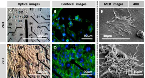
To study to possibility of cells to grow on modified surfaces, human neuroblastoma SH-SY5Y cells were cultivated on PEDOT:CNF-modified MEAs to investigate the cell adhesion and neurite outgrowths on the modified microelectrodes. As shown in Fig. 6 (A and C), After 24 and 72 h, SH-SY5Y cells grew uniforrnly and appeared to have spread homo geneously, demonstrating a good viability on the MEA substrate, even at 24 h, as no cell repulsion was found around coated electrodes. In order to investigate the state of SH-SY5Y cells cultured in detail, further work was conducted by fluorescent staining. As shown in Fig. 6 (B and D), SH SYSY cells grew evenly overall, and neurites were clearly observed on the composite materials. These results indicate that PEDOT:CNF com posite is well-suited for the adhesion and neurite outgrowth of SH-SY5Y cells.
The morphology of the cells on the PEDOT:CNF microelectrodes was also assessed through SEM. SH-SY5Y cells were seeded in the MEA and cultured for 48 h, then the fixation procedure was perforrned before proceeding to the SEM observation. Individual cells can be clearly recognized on the top of the PEDOT:CNF microelectrodes in Fig. 6 (E and
Fig. 6. In vi.tro cytotoxicity assay & cell morphology assessment. Optical images showing SH-SYSY cult1vated on top of the PEDOT:CNF coated microelectrodes array for (A) 24 h and (C) 72 h. The corresponding phalloidin-AM fluorescent images showing SH-SYSY cultivated on top of the PEDOT:CNF coated microelectrodes array for (B) 24 h and (D) 72 h. SEM images of SH-SYSY cells cultured 48 h on functionalized PEDOT:CNF microelectrodes surface. (E) Cell completely interfaced in 3D manner with a PEDOT:CNF-modified microelectrode, with clear interfacing with fi.ber network of the electrode. (F) PEDOT:CNF microelectrode being colonized a cell.
F). The SH-SY5Y cells display extensive processes and appear to be well attached on the surface of the PEDOT:CNF material. It is worth mentioning that the cells did not exhibit any particular preference for different materials Le. gold or MEA passivation layer and, as can be observed, they spread homogeneously on the surface of the MEA. The attachment of cells on PEDOT:CNF coated microelectrode shown in SEM images means that it is possible to the get direct, reliable and functional contact with the target tissue required for interfacing purposes. For example, when accurate electrophysiology recordings are required, a single unit may be detected and recorded when the recording device is very close from the targeted single neuron.
4. Conclusions
We have successfully demonstrated the feasibility of PEDOT:CNF composite material on gold microelectrode arrays by a simple and reproducible electrodeposition method. PEDOT was used to electro chemically entrap oxidized carbon nanofibers as dopants in one step, without the need of time-consuming multi-step processes. The combi nation of CNFs and PEDOT resulted in as strong synergetic effect be tween the two components in the composite leading to remarkable electrochemical properties, combining low impedance, high charge in jection capability, as well as a reliable neurotransmitter monitoring. The results from this study suggest the great potential of PEDOT:CNF com posites for developing next-generation microelectrodes for applications in neural therapies. We are currently running in vivo studies to show that PEDOT:CNF microelectrodes implanted in the cerebral cortex can detect neuronal activity with remarkably high signal-ta-noise ratio in an area as small as an individual neuron. We also envision the use the PEDOT:
CNF microelectrodes for neurochemicals monitoring in vitro and in vivo using fast scan cyclic voltammetry techniques.
Funding sources
This work was supported by ANR Neuro MEDDLE Grant ANR-15-CEl 9-0006 and ANR 3DBrain Grant ANR-19-ANR-15-CEl 9-0002-01.
Declaration of competing interest
The authors declare that they have no known competing financial interests or persona! relationships that could have appeared to influence the work reported in this paper.
CRediT authorship contribution statement
Valentin Saunier: Investigation, Writing review & editing. Emmanuel Flahaut: Investigation, Writing - review & editing. Marie Charline Blatché: Investigation, Validation. Christian Bergaud: Su pervision, Resources, Investigation, Writing - review & editing. Ali Maziz: Supervision, Resources, Methodology, Investigation, Writing
-review & editing.
Acknowledgment
We thank Dr. Anne-Marie Galibert and Dr. Brigitte Soula (CIRIMAT, Université de Toulouse, CNRS, F-31062, France) for help in the work on raw carbon nanofibers. We thank M. Jean-Baptiste Doucet and M. Julien Roui for help and guidance during FT-IR measurements. The authors acknowledge fundings from the Agence Nationale de la Recherche (ANR-15-CE19-0006 and ANR-19-CE19-0002-01). This work was sup ported by French RENA TECH network.
Appendix A. Supplementary data
Supplementary data to this article can be found online at https:/ /doi. org/10.1016/j. bios.2020.112413.
References
Abidian, M.R., Martin, D.C., 2009. Adv. Funct. Mater. 19 (4), 573-585.
Abidian, M.R., Corey, J.M., Kipke, D.R., Martin, D.C., 2010. Small 6 (3), 421--429.
Abidian, M.R., Ludwig, K.A., Marzullo, T.C., Martin, D.C., Kipke, D.R., 2009. Adv. Mater.
21 (37), 3764-3770.
V. Saunier et al
Anothurn.akkool, B., Bhange, S.N., Unni, S.M., Kurungot, S., 2013. RSC Adv. 3 (29), 11877-11887.
Ansaldo, A., Castagnola, E., Maggiolini, E., Fadiga, L., Ricci, D., 2011. ACS Nana 5 (3), 2206--2214.
Aqrawe, Z., Montgomery, J., Travas-Sejdic, J., Svirsk.is, D., 2018. Sensor. Actuator. B Chem. 257, 753-765.
Asplund, M., Thaning, E., Lundberg, J., Sandberg-Nordqvist, A.C., Kostyszyn, B.,
Inganas, O., Von Holst, H., 2009. Biomed. Mater. 4 (4).
Beaulieu, J.M., Gainetdinov, R.R., 2011. Phannacol. Rev. 63 (1), 182-217.
Berggren, M., Richter-Dahlfors, A., 2007. Adv. Mater. 19 (20), 3201-3213.
Bortolamiol, T., Lukanov, P., Galibert, A.-M., Soula, B., Lonchambon, P., Datas, L.,
Flahaut, E., 2014. Carbon 78, 79-90.
Carhart-Harris, R.L., Nutt, D.J., 2017. J. Psychophannacol. 31 (9), 1091-1120.
Carli, S., Lambertini, L., Zucchini, E., Ciarpella, F., Scarpellini, A., Prato, M.,
Castagnola, E., Fadiga, L., Ricci, D., 2018. Sensor. Actuator. B Chem. 271, 280--288.
Castagnola, V., Bayon, C., Descamps, E., Bergaud, C., 2014. Synth. Met. 189, 7-16.
Castagnola, V., Descamps, E., Lecestre, A., Daban, L., Remaud, J., Nowak, L., Bergaud, C.,
2015. Biosens. Bioelectron. 67, 450--457.
Cogan, S.F., 2008. Annu. Rev. Biomed. Eng. 10, 275-309.
Fabretto, M.V., Evans, D.R., Mueller, M., Zuber, K., Hojati-Talemi, P., Short, R.D.,
Wallace, G.G., Murphy, P.J., 2012. Chem. Mater. 24 (20), 3998-4003.
Gerwig, R., Fuchsberger, K., Schroeppel, B., Llnk, G.S., Heusel, G., Kraushaar, U.,
Schuhmann, W., Stett, A., Stelzle, M., 2012a. Front. Neuroeng. 5, 8.
Gerwig, R., Fuchsberger, K., Schroeppel, B., Llnk, G.S., Heusel, G., Kraushaar, U.,
Schuhmann, W., Stett, A., Stelzle, M., 2012b. Front. Neuroeng. 5, 8.
Green, R., Abidian, M.R., 2015. Adv. Mater. 27 (46), 7620--7637.
Heim, M., Yvert, B., Kuhn, A., 2012. J. Physiol. Paris 106 (3-4), 137-145.
Hess, L.H., Jansen, M., Maybeck, V., Hauf, M.V., Seifert, M., Stutzmann, M., Sharp, I.D.,
Offenhü.usser, A., Garrido, J.A., 2011. Adv. Mater. 23 (43), 5045-5049.
Huang, J., Llu, Y., Hou, H., You, T., 2008. Biosens. Bioelectron. 24 (4), 632-637.
Koehne, J.E., Marsh, M., Boakye, A., Douglas, B., Kim, I.Y., Chang, S.-Y., Jang, D.-P.,
Bennet, K.E., Kimble, C., Andrews, R., 2011. Analyst 136 (9), 1802-1805.
Kozai, T.D., Catt, K., Du, z., Na, K., Srivannavit, O., Haque, R.U., Seymour, J., Wise, K.O.,
Yoon, E., Cui, X.T., 2016. IEEE Trans. Biomed. Eng. 63 (1), 111-119.
Larsen, S.T., Vreeland, R.F., Heien, M.L., Taboryski, R., 2012. Analyst 137 (8), 1831-1836.
Lecomte, A., Degache, A., Descamps, E., Daban, L., Bergaud, C., 2017. Sensor. Actuator. B Chem. 251, 1001-1008.
Llu, Y., Huang, J., Hou, H., You, T., 2008. Electrochem. Commun. 10 (10), 1431-1434.
Ludwig, K.A., Uram, J.O., Yang, J., Martin, D.C., Kipke, D.R., 2006. J. Neural. Eng. 3 (1), 59.
Luo, X., Weaver, C.L., Zhou, D.D., Greenberg, R., Cui, X.T., 2011a. Biomaterials 32 (24), 5551-5557.
Luo, X., Weaver, C.L., Zhou, D.D., Greenberg, R., Cui, X.T., 2011b. Biomaterials 32 (24), 5551-5557.
Mand.al, H.S., Kastee, J.S., McHail, D.G., Rubinson, J.F., Pancrazio, J.J., Dumas, T.C.,
2015. Neuromodulation 18 (8), 657---663.
Maziz, A., Simaite, A., Bergaud, C., 2017. Polymerized Ionie Llquids. Royal Society of
Chemistry, pp. 456--488.
Maziz, A., Plesse, C., Soyer, C., Cattan, E., Vidal, F., 2015. ACS Applied Materials & Interfaces.
Maziz, A., Plesse, C., Soyer, C., Chevrot, C., Teyssié, D., Cattan, E., Vidal, F., 2014. Adv.
Funct. Mater. 24 (30), 4851-4859.
Meng, L., Turner, A.P., Mak, W.C., 2019. ACS Appl. Mater. Interfaces 11 (37), 34497-34506.
Nguyen-Vu, T.B., Chen, H., Cassen, A.M., Andrews, R., Meyyappan, M., Li, J., 2006. Small 2 (1), 89-94.
Nicolelis, M.A., Dimitrov, D., Caimena, J.M., Crist, R., Lehew, G., Kralik, J.O., Wise, S.P.,
2003. Proc. Natl. Acad. Sei. Unit. States Am. 100 (19), 11041-11046.
Polidori, M.C., Stahl, W., Eichler, O., Niestroj, I., Sies, H., 2001. Free Radie. Biol. Med. 30 (5), 456--462.
Polikov, V.S., Tresco, P.A., Reichert, W.M., 2005. J. Neurosci. Methods 148 (1), 1-18.
Rasheed, A., Howe, J.Y., Dadmun, M.D., Britt, P.F., 2007. Carbon 45 (5), 1072-1080.
Rebscher, S.J., Hetherington, A., Bonham, B., Wardrop, P., Whinney, D., Leake, P.A., 2008. J. Rehabil. Res. Dev. 45 (5), 731.
Reddy, S., Xiao, Q., Liu, H., Ll, C., Chen, S., Wang, C., Chiu, K., Chen, N., Tu, Y.,
Ramakrishna, S., 2019. ACS Appl. Mater. Interfaces 11 (20), 18254-18267.
Santangelo, S., Messina, G., Faggio, G., Abdul Rahim, S.H., Milone, C., 2012. J. Raman Spectrosc. 43 (10), 1432--1442.
Schmidt, C.E., Shastri, V.R., Vacanti, J.P., Langer, R., 1997. Proc. Natl. Acad. Sei. Unit. States Am. 94 (17), 8948--8953.
Shin, H.-J., Jeon, S.S., lm, S.S., 2011. Synth. Met. 161 (13-14), 1284-1288.
Smela, E., 2003. Adv. Mater. 15 (6), 481-494.
Su, C.-H., Sun, C.-L., Liao, Y.-C., 2017. ACS Omega 2 (8), 4245-4252.
Taylor, I.M., Rabbins, E.M., Catt, K.A., Cod.y, P.A., Happe, C.L., Cui, X.T., 2017. Biosens.
Bioelectron. 89, 400--410.
Temmer, R., Maziz, A., Plesse, C., Aabloo, A., Vidal, F., Tamm, T., 2013. Smart Mater. Stroct. 22 (10), 104006.
Tran-Van, F., Garreau, S., Lou.aI11, G., Frayer, G., Chevrot, C., 2001. J. Mater. Chem. 11 (5), 1378-1382.
Venkatraman, S., Hendricks, J., Richardson-Burns, S., Jan, E., Martin, D., Cannena, J.M., 2009. 4th International IEEE/EMBS Conference on Neural Engineering. IEEE, pp. 383-386.
Venkatraman, S., Hendricks, J., King, Z., Sereno, A., Richardson-Burns, S., Martin, D.,
Cannena, J., 2011. IEEE Transactions on 19, 307-316.
Vreeland, R.F., Atcherley, C.W., Russell, W.S., Xie, J.Y., Lu, D., Laude, N.D., Porreca, F.,
Heien, M.L., 2015. Anal. Chem. 87 (5), 2600--2607.
Wagenaar, D.A., Madhavan, R., Pirre, J., Patter, S.M., 2005. J. Neurosci. 25 (3), 680-688.
Wang, K., Fishman, H.A., Dai, H., Harris, J.S., 2006. Nano Lett. 6 (9), 2043-2048.
Wang, K., Frewin, C.L., E.srafilzadeh, D., Yu, C., Wang, C., Pancrazio, J.J.,
Romero-Ortega, M., Jalili, R., Wallace, G., 2019. Adv. Mater. 31 (15), 1805867.
Wang, W., Xu, G., Cui, X.T., Sheng, G., Luo, X., 2014. Biosens. Bioelectron. 58, 153-156.
Weaver, C., Li, H., Luo, X., Cui, X., 2014. J. Mater. Chem. B 2 (32), 5209-5219.
Wu, L., Zhang, X., Ju, H., 2007. Anal. Chem. 79 (2), 453-458.
Xu, G., Li, B., Cui, X.T., Ling, L., Luo, X., 2013. Sensor. Actuator. B Chem. 188, 405-410.
Yoon, H., Jang, J., 2009. Adv. Funct. Mater. 19 (10), 1567-1576.