THÈSE
En vue de l’obtention du
DOCTORAT DE L’UNIVERSITÉ DE TOULOUSE
Délivré par l'Université Toulouse 3 - Paul Sabatier
Présentée et soutenue par
Yassine MOTIE
Le 30 août 2019
Interopérabilité entre dispositifs hétérogènes en environnement
ouvert pour la mise en oeuvre de co-simulation
Ecole doctorale : EDMITT - Ecole Doctorale Mathématiques, Informatique et
Télécommunications de Toulouse
Spécialité : Informatique et Télécommunications
Unité de recherche :
IRIT : Institut de Recherche en Informatique de Toulouse
Thèse dirigée par
Alexandre NKETSA et Philippe TRUILLET
Jury
M. Reinhard GERNDT, Rapporteur M. Gregory ZACHAREWICZ, Rapporteur
M. Rashid SALEEM, Examinateur Mme Marie-Pierre GLEIZES, Examinatrice M. Alexandre NKETSA, Directeur de thèse M. Philippe TRUILLET, Co-directeur de thèse
I would like to present my sincere thankfulness to my dear father and my whole family for their great role in my life and their numerous sacrifices for me.
I would like to express my gratitude to all those who helped me during my PhD study. Many people have made invaluable contributions, both directly and indirectly to my research.
My deepest gratitude goes first and foremost to Professor Alexandre NKETSA, my supervisor, for his constant encouragement and guidance. Without his consistent and illuminating instruction, this thesis could not reach its present form.
To my co-supervisor Associate Professor Philippe TRUILLET, thank you for your kindness of looking after me wholeheartedly, for teaching me to be less "good student" and more autonomous throughout this research work.
To Professor Marie-Pierre Gleizes the Manager of the neOCampus scientific and interdisciplinary operation which aims at designing a smart, innovative, sustainable campus at Toulouse III Univer-sity. You provide for me a model of courage and determination.
I would like to thank Gregory Zacharewicz and Reinhard Gerndt for agreeing to read this thesis and to be rapporteurs and Rashid Saleem to be one of the examinators.
To all my collegues in neOCampus operation who accept to share their data and work and ex-planations in order to ease the integration of the whole and particularly to my firend Dr Elhadi Belghache who has a sense of sharing without equal.
To Professor Sahraoui Abd-El-Kader who was there at the worst of times to restore my confidence and who often suggested me new leads and articles to facilitate my research.
To all the Teams ELIPSE in IRIT and ISI in LAAS-CNRS. Your kindest let me feel the warmth of home when I am studying in Toulouse.
I also thank the members of the jury and in particular my thesis reporters
Le grand nombre de fonctionnalités d’appareils électroniques qu’on utilise quotidiennement en-traîne le passage d’une vision centrée sur des anciennes machines multifonctions vers des appareils variées en interaction distribués et éparpillés dans l’environnement. Sachant qu’un système est un ensemble intégré d’éléments (produits, personnels, processus) connectés et reliés entre eux, en vue de satisfaire, dans un environnement donné, un ou plusieurs objectifs définis et ayant des caractéristiques comme les composants qui le constituent, les relations entre ces composants, son environnement, les contraintes qu’il subit, les évolutions au cours du temps. La combinaison de ces derniers nous conduit à qualifier certains systèmes comme étant complexes dû à l’hétérogénéité des composants les constituant, à leurs évolution à diverses échelles de temps et à leurs répartition géographique intégrant des systèmes numériques, physiques et/ou des opérateurs humains dans la boucle. La difficulté d’avoir une bonne vision du système quand il est complexe (dispositifs réels et d’autres simulés) et la probabilité d’erreur de conception importante nous amène à réfléchir sur la possibilité de spécifier le produit et vérifier la conception à l’aide d’un prototype virtuel, on parle de simulation.
Quand un système complexe nécessite l’emploi de différents composants spécifiés par différents concepteurs travaillant sur des domaines différents, ceci augmente fortement le nombre de proto-types virtuels. Ces différents composants ont malheureusement tendance à demeurer trop indépen-dants les uns des autres empêchant ainsi à la fois les différents concepteurs de collaborer et leurs systèmes d’être interconnectés en vue de remplir une ou plusieurs tâches qui ne pourraient pas être accomplies par l’un de ces éléments seulement. Le besoin de communication et de coopération s’impose. Cela doit tenir compte des différents acteurs et les coordonner dans leurs interactions au sein de ce système complexe. Or les avancées en simulation dans chacun des domaines sont considérables, chacun disposant de ses propres logiciels. Des solutions d’interopérabilités sont donc nécessaires pour la mise en oeuvre d’une co-simulation encourageant le dialogue entre les disciplines et réduisant les erreurs, le coût et le temps de développement.
Dans notre thèse nous participons à la conception d’un système de co-simulation qui intègre différents outils de simulation-métiers basés sur la modélisation du comportement de dispositifs comme la simulation énergétique et la simulation d’usure de matériaux de construction au sein de la même plateforme
Après la prise en compte des notions d’architecture, de communication (entre les simulateurs ou avec les utilisateurs) et de visualisation pour définir les modèles d’architecture. Nous analysons l’architecture gérant l’interopérabilité. Nous proposons une approche d’interopérabilité se basant sur la réutilisation et l’échange de composants de calculs. Nous aborderons successivement les problématiques liées aux niveaux structurel et sémantique d’interopérabilité, aux stratégies co-simulation, aux méthodes de conception du modèle de tâches permettant la construction de com-posants boite noire. Puis nous présenterons la mise en application concrète de notre méthodologie de conception globale et de l’outil de vérification de certaines propriétés de l’architecture, comme la cohérence et la sémantique.
The large number of electronic device features we use on a daily basis means a shift from a vision of old multifunction machines to distributed, widely distributed distributed devices in the environment. Knowing that a system is an integrated set of connected and interrelated elements (products, people, processes) in order to satisfy, in a given environment, one or more defined objectives and having characteristics such as the components that constitute it , the relations between these components, its environment, the constraints it undergoes, evolutions over time. The combination of these leads us to qualify some systems as complex due to the heterogeneity of the components constituting them, their evolution at various time scales and their geographical distribution integrating digital systems, physical and / or human operators in the loop. The difficulty of having a good vision of the system when it is complex (real and other simulated devices) and the probability of significant design error leads us to reflect on the ability to specify the product and verify the design using a virtual prototype, we are talking about simulation.
When a complex system requires the use of different components specified by different designers working on different domains, this greatly increases the number of virtual prototypes.
These different components unfortunately tend to remain too independent of each other thus pre-venting both the different designers from collaborating and their systems from being interconnected in order to fulfill one or more tasks that could not be accomplished by one of these elements only. The need for communication and cooperation is needed. This must take into account the different actors and coordinate them in their interactions within this complex system. But the advances in simulation in each area are considerable, each with its own software. Interoperability solutions are therefore necessary for the implementation of a co-simulation encouraging dialogue between disciplines and reducing errors, cost and development time.
In our thesis we participate in the design of a co-simulation system which integrates different tools of simulation-trades based on the modeling of the behavior of devices like the simulation energetics and the simulation of wear of building materials within the same platform.
After taking into account the concepts of architecture, communication (between simulators or with users) and visualization to define architecture models. We analyze the architecture that man-ages interoperability. We propose an interoperability approach based on the reuse and exchange of computational components. We will successively address the issues related to the interoperability structural and semantic levels, the co-simulation strategies, the design methods of the task model al-lowing the construction of black box components. Then we will present the concrete implementation of our global design methodology and the verification tool of some properties of the architecture, such as coherence and semantics.
AI: Artificial intelligence AIKM: AI Knowledge Map
ALSP: Aggregate Level Simulation Protocol AMAS: Adaptive Mutli-Agent Systems
AMOEBA: Agnostic Model builder by self Adaptation API: Programming Interface
AUTOSAR: AUTomotive Open System ARchitecture BCVTB: Building Controls Virtual Test Bed
BIM: Building Information Modeling
BPMN: Business Process Model and Notation
CCSIL: Command Control Simulation interface Language COM: Component Object Model
CORBA: Common Object Request Broker Architecture CS: Co-simulation
DAE: Algebraic Differential Equations DAI: Distribution of Artificial intelligence DEVS: Discrete Event System Specification DIS: Distributed interactive simulation DLL: Dynamic Link Library
DOD: Departement Of Defense
DREAM: Dynamic Data Relation Extraction using Adaptive Multi-Agent System FIFO: First In First Out
FMI: Functional Mockup Interface FMU: Functional Mockup Units FOM: Federation Object Model GDS: Generic Data System
HCI: Human Computer Interaction HDL: Hardware Description Language HLA: High Level Architecture
IAI: International Alliance for Interoperability ICAR: Interface for Component Architecture ICT: Information and Communication Technologies IDL: Interface Description Language
IEEE: Institute of Electrical and electronics Engineers IFC: Industry foundation classes
IP: Internet Protocol IT: Information Technology JAR: Java archive
LCIM: Levels of Conceptuals Interoperability Models MAS: Mutli-Agent Systems
MBDM: Model Based Data Management MDA: Model Driven Architecture
MECSYCO: Multi-agent Environment for Complex System CO-simulation MPI: Message Passing Interface
MUSE: Multiple Unified Simulation Environment NECSI: New England Complex System Institute NCS: Non Cooperative Situations
ODBC: Open Database Connectivity ODE: Ordinary Differential Equations OMT: Object Model Templates OWL: Web Ontology Language PDE: Partial Differential Equations PDU: Protocol Data Units
QSS: Quantized State System
RDF: Resource Description Framework RTI: Runtime infrastructure
SEDRIS: Synthetic environment Data Representation & Interchange Specification SIMNET: Simulation Networking
SPARQL: SPARQL Protocol and RDF Query Language SSGM: Subsystem to Subsystem Graph Model
TCP: Transmission Control Protocol UDP: User Datagram Protocol UML: Unified Modeling Language
USAFE: United States Air Forces in Europe UX: User eXperience
CHAPTER I: Introduction and motivations
13
1 work environment 13
2 Modeling and Simulation 16
CHAPTER II: Interoperability and Issues in the smart campus
pro-cess
23
1 Building a Smart campus at Toulouse III Paul Sabatier University 23
1.1 Smart campus Concept . . . 23
1.2 Smart campus: complex system . . . 24
1.3 Our Smart campus . . . 26
2 Support the design process through interoperability 29 2.1 Definition, issues and concepts of interoperability . . . 30
2.1.1 Definition of interoperability . . . 30
2.1.2 Languages to represent interoperability . . . 30
2.2 Model-Based Interoperability . . . 31
2.3 levels of conceptual interoperability models (LCIM) . . . 32
2.4 Structural and semantic interoperabilities . . . 33
2.4.1 Issues: The heterogeneity of the models . . . 34
2.4.2 Issues: The opening of the simulators . . . 36
2.5 Existing solutions and interoperability standards . . . 37
2.5.1 Solutions for interoperability . . . 37
2.5.2 Interoperability Standards . . . 41
2.5.3 Discussion . . . 46
3 Interoperability layers (Structural and Semantic) 47 3.1 Structural interoperability based FMI . . . 47
3.1.1 FMI: Functional Mockup Interface . . . 47
3.1.2 Functional Mockup Units (FMU) . . . 48
3.1.3 FMI description schema . . . 49
3.1.4 C-interface . . . 49
3.1.5 FMI for Model Exchange (ME) . . . 51
3.1.6 FMI for Cosimulation (CS) . . . 51
3.1.7 Enumerations of variables . . . 52
3.1.8 FMI implementation . . . 53
3.2 Data mediation based on semantical interoperability . . . 53
3.2.1 Data mediation . . . 53
3.2.2 Types of mediation . . . 55
CHAPTER III: Coupling of heterogeneous simulations using Co-simulation
59
1 Co-simulation (co-operative simulation ) 59
2 Synchronisation models 60
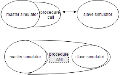
2.1 Master-slave distributed architecture . . . 60
2.2 bus-based distributed architecture . . . 62
2.3 Co-simulation bus . . . 64
3 Co-simulation tools 66 3.1 Business field . . . 67
3.2 Research field . . . 68
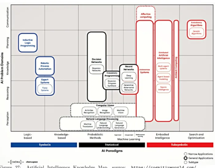
4 Classification of AI approaches 69 4.1 AI knowledge Map (AIKM) . . . 69
4.2 Adaptive Multi-Agent Systems (AMAS) and Other semantic approaches . . . 71
CHAPTER IV: Co-simulation framework
73
1 Co-simulation framework interoperability 73 1.1 Interoperability based mediation model . . . 741.2 The co-simulation framework based component . . . 76
1.2.1 Simulator . . . 76
1.2.2 Cosimate-FMI . . . 76
1.2.3 System . . . 76
1.3 neOCampus case study . . . 77
1.3.1 Different simulators used . . . 77
1.3.2 Co-simulation engine . . . 77
1.3.3 Mediator components . . . 78
1.4 Managing Data in Dynamic Complex Systems . . . 80
2 Collective Artificial Intelligence for Semantic Interoperability 82 2.1 Multi-Agent Systems Theory . . . 82
2.2 Adaptive Multi-Agent Systems . . . 83
2.3 Adapt the System by its Parts . . . 84
2.4 Behaviour of an AMAS Agent . . . 85
2.5 Interoperability based Dynamic Data Mediation using Adaptive Multi-Agent Systems 86 2.5.1 Multi-Agent Systems . . . 86
2.5.2 Self-Adaptive Multi-Agent Systems . . . 86
2.6 Dynamic Data Relation Extraction using AMAS . . . 86
3 Dynamic Data Mediation 93
3.1 Dynamic Subsystem-to-Subsystem Graph Model . . . 94
3.1.1 Initialization Behavior . . . 95
3.1.2 Nominal Behavior . . . 95
3.2 Data Translation using AMOEBA . . . 95
3.3 Model Calibration . . . 97
3.4 neOCampus Use Case . . . 98
3.5 DreAMoeba Mediator . . . 98
CHAPTER V: Conception Methods for and with the user
105
1 Conception Methods for and with the user 105 1.1 Problematic . . . 1051.2 Accessible Interface design . . . 110
1.3 Ergonomic criteria . . . 114
1.4 User interface - FMU . . . 116
1.5 Scenario of tasks to generate an FMU from java program . . . 117
1.6 Pre-experiment . . . 125
1.7 Participants . . . 125
1.8 Equipment . . . 126
1.9 Procedure . . . 126
1.10 Analysis . . . 126
2 Preliminary results and discussion 127
3 Conclusion and discussion 128
CHAPTER VI: Conclusion and future work
131
1 modeling and Simulation representation . . . 18
2 Overview of co-simulation of two subsystems . . . 19
3 Overview of neOCampus sensors . . . 27
4 Toulouse’s connected campus . . . 29
5 Levels of Conceptual Interoperability Model . . . 33
6 Enterprise interoperability framework - Source: [Chen, 2006] . . . 34
7 White box/black box/gray box approach - Source: [Gaaloul, 2012] . . . 36
8 causal approach (oriented) / acausal approach (unoriented) . . . 36
9 interaction between two Components . . . 40
10 High level view, logic of a HLA Federation execution[Zacharewicz, 2006]. . . 43
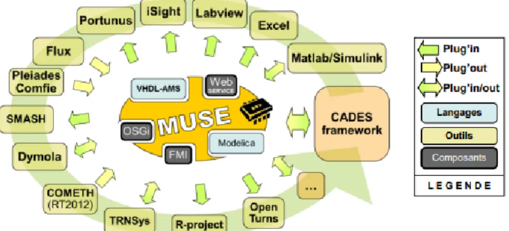
11 The communication capability MUSE. Source: (MUSE) . . . 44
12 Hierarchical architecture of object/component/service, and dynamic/coupling com-promise. - Source: [Delinchant et al., 2012] . . . 44
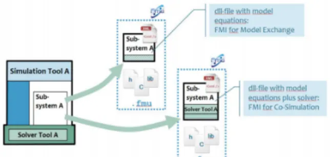
13 FMU for the dynamic simulation . . . 46
14 Overview of FMI . . . 47
15 Models Exchange vs cosimulation. Source: https://fmi-standard.org/ . . . 48
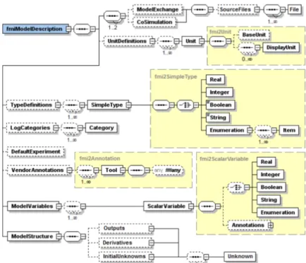
16 FMI description schema. source: AIT Austrian Institute of Technology, ERIGrid JRA2 Workshop . . . 49
17 Capability flags of FMI for Co-Simulation . . . 50
18 The "fmiTypesPlatform" header file, source: [Blochwitz et al., 2012] . . . 51
19 data mediation . . . 55
20 components mediation . . . 56
21 Encapsulation of formalisms. Source: [Siebert, 2011] . . . 58
22 Co-simulation of heterogeneous models. Source: [Siebert, 2011] . . . 59
23 Example of a master-slave co-simulation platform . . . 60
24 absence of parallelism in master-slave . . . 63
25 Example of a distributed co-simulation platform . . . 64
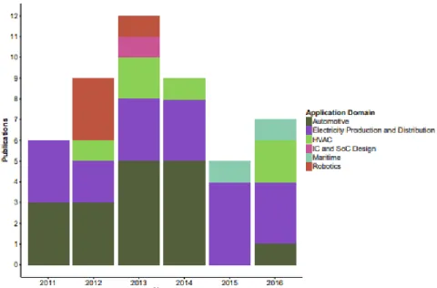
26 Research publications of co-simulation applications over the past five years. Source: [Gomes et al., 2017] . . . 66
27 Artificial Intelligence Knowledge Map, source: https://cognitiveworld.com/article/ ai-knowledge-map . . . 71
28 components mediation . . . 78
29 Conventional data analytics pipeline . . . 81
30 Distributed data analytics pipeline . . . 82
31 AMAS based data analytics pipeline . . . 83
32 Adaptation: changing the function of the system by changing its organization . . . . 84
33 Data relation graph . . . 87
34 Pearson’s correlation plot . . . 89
35 Pearson’s correlation plot . . . 89
36 Phase space similarity . . . 90
37 Phase space similarity . . . 91
38 A snapshot of one Context agent at a given time T (its validity ranges) . . . 92
40 An example of AMOEBA context agents. (a) A context agent and its inputs ranges. (b) The mapping of a two dimensional data spaces (graphical representation of the
context agents) . . . 93
41 Co-simulation Architecture using DreAMoeba mediator . . . 94
42 Example of Subsystem-to-Subsystem Graph Model building with DREAM . . . 96
43 AMOEBA learns the data combinations . . . 98
44 Luminosity and temperature data recorded by neOCampus sensors during one week. 99 45 Couple translation by AMOEBA when the most confident contexts is one value . . . 101
46 Couple translation by AMOEBA when the most confident contexts is a range . . . . 102
47 Our user-centered design approach . . . 105
48 Our framework phases and HCI need . . . 109
49 activity diagram for FMU generation . . . 116
50 step 0 - FMU generation task . . . 118
51 step 1 - FMU generation task . . . 118
52 step 2 - FMU generation task . . . 119
53 step 3 - FMU generation task . . . 119
54 step 4 - FMU generation task . . . 120
55 step 5 - FMU generation task . . . 120
56 step 6 - FMU generation task . . . 121
57 step 7 - FMU generation task . . . 121
58 step 8 - FMU generation task . . . 122
59 Low-fidelity models implementing the scenario . . . 123
60 Low-fidelity model resulting from task analysis . . . 124
61 FMI component generation process . . . 125
62 Screen-shot of the proposed interface . . . 126
63 Results – task completion time . . . 127
CHAPTER I: Introduction and motivations
1
work environment
The "smart city" is no longer a futuristic dream, the impact of digital in urban development is now a reality. In 2016, it is estimated that 54,5% of the worlds population is urban and the urban population is expected to continue to grow so that by 2050, it is expected that 7/10 of the population will live in urban centers[Group, 2014]. Due to this increase of urban population, the challenge of rethinking the concept of a city sprang. As Laurence Lafont, Public Sector Director at Microsoft France, said: "Digital is not an end in itself; the question is rather how will it help cities to transform and develop". The smart city proposes to use Information and Communication Technologies (ICT) to design technologies which should respond to people’s needs through sustain-able solutions for social and economic aspects [Albino et al., 2015]. As computer designers, our attempt to make our university campus smart and sustainable as part of the neOCampus initiative is fraught with problems. The desire to study particular aspects of smart cities illustrates the need for interdisciplinary work.
The neOCampus operation, which is our first and main motivation in this work, aims to study and implement the concepts of Smart Cities in the University campus of Toulouse III Paul Sabatier. Many initiatives have been launched, mainly the study of the impact of human activity on the campus footprint. But these applications have to face technological challenges such as their hetero-geneity, their spatial distribution or the number of entities involved. These characteristics make it mandatory to consider smart cities as complex systems and to approach them with an interdisci-plinary approach.
work complexity Designing an interactive system is a difficult task. Designing and evaluating a so-called "complex" system is even more so.
From a software point of view, a system can be seen as an integrated set of elements interconnected with each other, in order to satisfy in a given environment one or more pre-defined objectives. The components of this system include both the facilities, the hardware and software equipment, the data, the services, the qualified personnel and the techniques necessary to achieve, provide and maintain its efficiency.
A complex system has many characteristics such as the heterogeneity of its components, their evolution at different time scales and their geographical distribution integrating both digital systems, physical and/or human operators. These complex systems are usually decomposed into subsystems, following either:
• top-down approach, if we have a holistically vision of a system (understanding each part of the system by first understanding the whole system)
• bottom-up approach - from existing components that need to be reused - if we have a reductionist vision of a system (introduced by R. Descartes, where we try to understand a
"system from the study of its individual components).
Three characteristics that determine a complex system can be distinguished, according to [Guck-enheimer and Ottino, 2008]:
• Its complex structure into several components and subsystems. We may also have a network that describes which components of a system interact.
• The behavior possibly emerging and interactions "not obvious" from the analysis issues of the subsystem. We frequently use the term emergent to describe behaviors that arise from the interaction of subsystems and are not evident from analysis of each subsystem
• Its adaptation as well as its evolution over time are characteristic of critical infrastructure systems and fundamental to the life sciences.
Complex systems are everywhere, starting by the universe, Earth’s global climate, organisms, the human brain, social and economic organizations and traffics. We usually focus on their characteristics while a unanimously accepted definition of their nature remains to be formalized. We also use the term system of systems alternatively when the functionality provided results from the composition of pre-existent systems with non-trivial interconnections. It offers more functionality and performance than simply the sum of the constituent systems. [Maier, 1998] distinguishes five traits for identifying system of systems challenges:
• Operational Independence of Elements: The component systems of the system of systems must be able to usefully operate independently. In other words, the components themselves fulfill the client-operator functions.
• Managerial Independence of Elements: Component systems are acquired and integrated sepa-rately, but maintain a continuous operational existence, independent of the system of systems.
• Evolutionary Development: A system of systems is never completely formed or complete. The development of these systems evolves over time and their structure, function and purpose are added, removed and modified as experience with the system develops and evolves over time.
• Emergent Behavior: The functions performed and purposes carried out don’t reside in any component system. They’re emergent properties of the entire system of systems. The princi-pal purposes supporting engineering of these systems are fulfilled by these emergent behaviors.
• Geographical Distribution of Elements: Systems can easily exchange only information and knowledge with one another, and not substantial quantities of physical mass or energy
As a result, we are led to the inability of these systems (subsystems) to speak the same language to each other and to share information effectively and correctly - to be interoperable - which is one of the major problems that complex systems frequently face. To achieve this cooperation on a global level, it seems important to opt for an open environment that allows continuous dialogue between the different parties.
Before going further, one should differentiate between interoperation dealing with how a complex system works, how its components exchange with each other and how they are orchestrated to hand over the required functionality to the user. The composition, on the other hand, focuses on what components and functionality can be integrated into systems without causing any failure, or creating problems with other components.
Following the categorization of[Page et al., 2004], admitting that composability deals with models, interoperability deals with their implementation, and integrability deals with the hardware and configuration side of connectivity.
As the integrability deals with the physical and technical connections between systems. This communication protocols exist for exchanging data between participating systems, and the com-munication infrastructure is established allowing systems to exchange bits and bytes, and that the underlying networks and protocols are unambiguously defined. We estimated that our contribution will not be on this low level. On the other hand, as we were dealing with models that some of them pre-exist and others are developed separately by experts in a parallel time, that conceptual models are unfortunetly not all documented based on engineering methods enabling their interpretation and evaluation by other engineers. We didn’t consider the alignment of issues on the modeling level (composability).
Thus, we focused our work on the interoperability dealing with the implementation details of inter-operation, which includes the exchange of data elements via required and provided interfaces, the use of middleware, mapping to common information exchange models.
We believe that a complex system (and its behavior, since the temporal dimension is indeed present) includes more than the sum of its individual components, possessing strong synergies between the sub-parts. In attempting to interoperate heterogeneous systems, a systemic approach based on holism must be taken into account.
Thus, to understand the functioning of the system as a whole, we must simultaneously study all its components and their interactions and not study each component in isolation. We distinguish the case where the components already exist, made by experts, so we focus on the interactions only. The other case is when we don’t have the component and we need to develop it, so the component’s component is a matter of fact. In addition, this holistic development process[Van der Auweraer et al., 2013] where the partial solutions developed independently are integrated sooner in the process and more frequently is the only way to achieve an innovative and optimal multi-disciplinary solutions.
2
Modeling and Simulation
The modeling and simulation (M&S) is a substitute for physical experimentation, in which comput-ers are used to compute the results of some physical and not physical phenomenon.As it’s apparent from its name "Modeling and simulation":
• Modeling is the process of producing a model; the model is, according to the US-DOD, all physical, mathematical, or other logic representation (abstraction) of a system, entity, process or a physical phenomenon. A model is similar to but can be simpler than the system it represents.
When a model is intended for a simulation study, we speak of a mathematical model developed with the help of simulation software. There are different ways to make a model classification. This could be done by system type, or by type of mathematical construction. This last way is more interesting since it deals with the mathematical and statistical aspects of the models, rather than how to represent a particular type of system. Acoording to modelia1, we
distinguish a partial list of a mathematical model types that are pretty widely used:
• Deterministic (input and output variables are fixed values)
• Stochastic (at least one of the input or output variables is probabilistic) • Static (time is not taken into account)
• Dynamic (time-varying interactions among variables are taken into account)
• Based on Partial Differential Equations (PDE) (systems vary according to several continuous variables)
• Individual-based (A set of individuals, rules of behavior, functions of the local environ-ment) similar types are:
• Cellular automata where the individuals are placed on the intersections of a network, and each intersection is occupied
• Multi-agent model where agents are the simulated individuals
• Simulation is defined according to IEEE Standard Glossary of Modeling and Simulation as an implementation of one or more models evolving over time and made for a specific purpose. It’s a tool to evaluate the performance of a system, existing or proposed, under different configurations of interest and over long periods of real time.
Simulation aims to reduce the chances of failure to meet specifications, to prevent under or
1http://www.modelia.org/html/050929_formationIntroModDec2005/supportsDesInterventions/
over-utilization of resources, to eliminate unforeseen bottlenecks, and to optimize system performance.
When studying the dynamics of systems to understand the behavior of complex systems over time, as in our case, two techniques are distinguished:
• Discrete event simulation is appropriate for systems having a continuous time base but inputs and state transitions occur at discrete time instances. The state transition consists of two parts: The external transition function which is executed whenever an input arrives and the internal transition function where the times of execution are scheduled by the time advance function. An example of such a system is the number of students in a library: The number of students is discrete (integer) and the number of students only changes when someone enters or leaves the library.
• Continuous simulation is appropriate for systems with a continuous state that changes continuously over time. An example of such a systems is the amount of liquid in a tank and or its temperature. So if we observe the water that heats, we do not consider any event: the water heats permanently, continually, and we choose to observe its temperature every second, every minute, every millisecond. No matter when one observes it, the water will have a temperature - according to which a decision can be made. Such a system can be described by differential equations. Continuous simulation is a technique to solve these equations numerically.
Models can be expressed in a variety of formalisms that can be understood as means for specifying subclasses of dynamic systems. These formalisms are chosen according to the objective of the study to be realized. Formal models, based on concepts and mathematical properties, have two dimensions: space and time[Zacharewicz, 2006].
We thus distinguish two classifications: the temporal classification whose representation of time can be discrete or continuous and the spatial classification where the space whose descriptive variables can take values in a finite or infinite set.
Keep in mind that digital computer simulation involves the discretization of time, space or both. Certain formalisms already have a discrete component, in the opposite case, it will be necessary to realize the discretization of the time or the space. For models described by differential equations2, time is discretized in digital integration techniques.
The CHEAr3 center distinguishes the most common simulation techniques based on the fields
of application and composition criteria:
• Numerical simulation: purely software, not real time
2Association of a time base and variables also continuous, the equations define the changes of states 3Centre des hautes études de l’Armement
• Hybrid simulation: it makes the digital and the continuous interact
• Interactive simulation: involves the human factor, war games
• Virtual simulation: piloted simulation, Human in the loop, reproduction of the real commands
• Instrumented simulation: integrates real hardware
• Real time simulation: when the respect of the temporal constraints in the execution of the treatments is as important as the result of these treatments
Note that some of these techniques overlap; Hybrid simulation, virtual simulation and instrumented simulation are real-time simulations. Numerical simulation can be interactive. Piloted simulation and instrumented simulation in many cases are interactive.
With these different types of simulations, their interoperability has emerged as a fundamental technique to enhance their applicability and minimize the cost of development and maintenance.
Simulation can show virtually (creating virtual scenes) how a real physical situation would hap-pen.
According to [Jara et al., 2010] computer modeling requires an analysis of the problem with the identification of the variables and the algorithms, and its implementation on a specific software platform. A computer simulation is an implementation of a model that allows us to test the model with different initial conditions with the objective of learning about the model’s behaviour. The applicability of the results of the simulation to those of the real system depends on how well the model describes reality. see(cf. Figure 1).
Since the modeling and simulation (M&S) [Friedman and Ghidella, 2006] doesn’t promote a holistic development process, they may only improve the development of the partial solutions, because of the difficulty to integrate models developed by different specialized tools or those with Intellectual Property.
Co-modeling could be an alternative way, assuming that models are described in a unified language, and then simulated. But each domain has its own particularities when it comes to simulation, making it impractical to find a language and simulation algorithm that fits all.
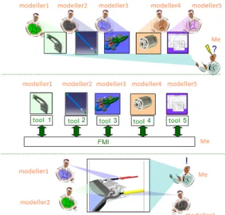
Co-simulation (cf. Figure 2) is defined, to overcome these challenges, as the coupling of several simulation tools where each tool deals with a part of a modular problem, where the data exchange is restricted to discrete communication points and where the subsystems are solved independently between communication points. This allows each designer to interact (and work on a subsystem) with the complex system in order to maintain its business expertise and continue to use its own digital tools. This designer can therefore use a variety of specification tools at different levels of abstraction. In addition, the design of the models may be subject to a competitive design, as teams design in different design times. Some may have finished while others pursue it, so competition is stimulated and motivates teams to speed up their activities.
A co-simulation, according to [Palensky et al., 2017], is composed of a set of coupled simulators that cooperate with each other. Each simulator has its own solver and works simultaneously and independently on its own model. The simulators are coupled by dynamically connecting the models using their input and output variables, so that the outputs of one simulator become the inputs of the other and vice versa. The variable exchange, time synchronization and execution coordination is, in the most general case, facilitated in runtime by a so-called master algorithm, which orches-trates the entire co-simulation. Aside from the validation aspects, software interoperability is often not given or possible, numerical phenomena and problems are sometimes even unsolvable.
As in our case where we’re dealing with complex, heterogeneous systems that can neither be in-vestigated in analytical nor in purely experimental fashion. Data exchanged and utilized between simulations has come to define their interoperability, such as messages ex-changed between simula-tors or actions defined between units on the strategic maps. Thus, interoperability of the various simulators requires standardized interfaces.
A complex system is also characterized by many people involved in its life cycle that includes design, development, manufacturing, operations, maintenance and decommissioning. That comes down to give extensive attention to the user characteristics, usability goals, environment, etc.
Among the constraints of the complexity to which we confront ourselves in our work, the manage-ment of the problems of organization in these units, with a significant human component, partici-pating in the neOCampus operation. The human operator brought to coexist and interact with our complex system, is at the same time, by its adaptive capacities the guarantor of the reliability, the flexibility and the reactivity, and paradoxically one of the main causes of insecurity. Uncertainties related to his behavior and his lack of knowledge of the global system hinder his good interaction with it and may reduce performances.
Long regarded as secondary, the human operator however takes more and more importance and proves, at the same time, the most difficult to control. Moreover, a part of our work addresses human-machine interaction, helping to understand and cooperate heterogeneous research units by focusing on the interactions of the human operator with the system in order to make the best use of its capabilities. Some of the principles that will ensure a design is human centered cited by [Endsley, 2016]are:
• The design is based upon an explicit understanding of users, tasks and environments. This comes down to know who are the users and what are the users tasks and goals.
• Users are involved throughout design and development.
• The design is driven and refined by user-centered evaluation.
• The process is iterative. A process for arriving at a decision or a desired result by repeating rounds of analysis or a cycle of operations.
• The design addresses the whole user experience. By understanding the user’s experience levels.
• The design team includes multidisciplinary skills and perspectives. Knowing for example if the user is multitasking.
In our thesis we participate in the design of a co-simulation system which integrates different tools of simulation-trades based on the modeling of the behavior of devices like the simulation energetics and the simulation of wear of building materials within the same platform.
After taking into account the concepts of architecture, communication (between simulators or with users) and visualization to define architecture models. We analyze the architecture that man-ages interoperability. We propose an interoperability approach based on the reuse and exchange of computational components. We will successively address issues related to the structural and semantic interoperability levels. Using, in an original way, respectively interoperability standards and a dynamic data mediation based on artificial intelligence, co-simulation strategies, task model design methods allowing the construction of black box components, based on an original user cen-tered design approach. Then we will present the concrete implementation of our global design methodology and the verification tool of some properties of the architecture, such as coherence and semantics.
In Chapter II, we present the issues related to the smart campus design process and will focus on the issues and concept of interoperability between campus business tools for dynamic simulation. We will introduce the existing interoperability solutions (data, models and computation codes) and we propose a new interoperability approach that will be used at each stage of the design process. and co-simulation tools
In Chapter III, we will be interested in the co-simulation of heterogeneous tools. We will define the co-simulation, and study the synchronization models (How data will be exchanged between models), and compare the advantages and the limits allowing us to make a specific choice to our context. Following which we will define the steps to build our framework.
In Chapter IV, we will be interested in the co-simulation framework interoperability and will detailed the one based mediation model and described the other based dynamic data mediation. For this last one we will present the adaptive multi-agent systems, then we will compare the two approaches.Finally, we will present the practical application of our global design methodologies on a multi-stakeholder, multi-business project. This is the neOCampus operation where we worked in close contact with many experts, as well as other industrial and academic partners.
In Chapter V, we will be interested in the conception methods for and with the user, then we will explain the needs to achieve a user centred design approach. This part of the work was a consequence of the interaction of neOCampus users with our framework. As they didn’t know how to generate the components needed to be plugged in our plateform from their own simulations. We will focus on the tasks model designed and interface developed for the black-box components generation. Finally we will present the interface advantages deducted by the statistical analysis made for that purpose following a HCI "Human Computer Interaction" approach.
Chapter VI will be the last chapter, contributions will be analyzed and a conclusion will be given as well as future work.
the smart campus process
1
Building a Smart campus at Toulouse III Paul Sabatier
University
1.1
Smart campus Concept
The societal, energy and economic context drives lot of Universities to place at the heart of their project of establishment another project: that of a smart campus, in partnership with all the political and economic actors of the territory, without forgetting the universities community (students, staff, teachers and researchers). This smart campus project has as missions to improve the university’s environmental impact to make it a sustainable and responsible campus, to evolve the campus towards a smart, digital, connected and responsible campus and to put it as an integrated element in a larger whole: a smart campus in a smart city. As a matter of fact, the Smart Cities concept is more than an economical approach to reduce maintenance costs of cities: it is a socio-ecological revolution, which intends to improve the symbioses between a city, the environment and the citizens[Ahvenniemi et al., 2017].
This concept of smart cities, or at small scale smart campus is original and systemic in its:
• Design: Smart campus crosses human constraints and opportunities with scientific and technological capabilities.
• Thinking: All research laboratories, in line with their areas of expertise, are working on experimenting with the smart campus of tomorrow.
• Implementation: An impressive number of actors from all strata of the university (students, researchers, teachers, administrative staff ...) participate.
• Scope: The entire territory collaborates and promotes a territorialized and decompartmen-talized approach to the sustainable city.
The smart campus concept has in general point of view, according to[Verstaevel et al., 2017], four fundamental aspects:
• The use of information and communication technologies (ICT) to manage the city’s assets, improving the efficiency of the services offered by the city.
• The improvement of the quality of life of residents by a digital transformation of their working and living environments.
• The central roles of citizens in this transformation, by orienting cities towards citizens needs and by an active implication of citizens in cities decisions thanks to the usage of ICT.
• The inter-disciplinarity aspect of researches on Smart Cities, implying many domains such as urbanization, social science or informatics.
1.2
Smart campus: complex system
We mentionned in the part 1 the focus on the data exchange. Data are the core of the smart campus, everything relies at some point on the data that are collected in the campus. As described in[Verstaevel et al., 2017]the ongoing projects of neOCampus, highlighting the cooperation between scientists from different fields and the mutual benefits for researchers management, and technical staffs, face some technological challenges such has their heterogeneity, their spatial distribution or the number of entities involved. Those characteristics make mandatory to see Smart Cities as complex systems.
Also from an Information technology (IT) designer point of view, smart campus applications share common properties which makes them complex systems[Harrison and Donnelly, 2011] [Verstaevel et al., 2017]:
• Large-scale: Due to the amount of entities (physical and virtual) involved in the Smart Campus, Smart Campus IT applications reach unprecedented scale in many dimensions such has the number of lines of code to develop an application, the amount of data stored, accessed, manipulated, and refined, the number of connections and interdependencies or the number of people involved and interactions that may occurred. We may even talk of Ultra-Large-Scale Systems.
• Non-Linearity: In Smart Campus, even the smallest causes can have large effects. For example, a change in the timing of a traffic light may results in huge traffic congestions. A non-linear system is a system in which the change of the output is not proportional to the change of the input. This non-linearity is a huge problem for ICT as it may lead to unpredictable or counter-intuitive situations, which makes the task of controlling these systems very complex.
• Heterogeneity: Smart Campus are composed of various heterogeneous devices. This heterogeneity implies challenges at various levels. The observation of Smart Campus through
a large scope of sensors, each sensor independently designed to observe a specific feature, results in producing large volumes of heterogeneous data. Those Big Data require new infrastructures to enable the exchange and storage of those information, but also requires to create new tools and norms to manage them. Indeed, sampling rates, data scales or data formats are as various as sensors are numerous. But this heterogeneity might also be a source towards innovative solutions.
• Openness: The openness property characterizes the ability of a system to deal with the appearance and disappearance of some of its parts. As Smart Campus are in constant urban mutations, ICT applications must deal with the appearance and disappearance of devices, and the data and action associated with. Openness is a crucial challenge for the large acceptance of new technologies and a key towards sustainability.
• Unpredictable Dynamics: Users activity is a huge source of those unpredictable be-haviours in Smart Campus. This unpredictability involves to provide to IT systems the ability to continuously self-adapt to changes that may occurs in the dynamics of the city.
• Spatial Distribution: At the opposite of centralized IT systems, where information is sent to a central node which takes the decisions and exercises control over the different components, , the spatial distribution of entities in Smart Campus invites to rest on the autonomy of the entities, decentralizing the control over the different entities.
• Privacy: Smart Campus are able to collect and gather large amount of information, and this could harm the privacy of end-users [Martínez-Ballesté et al., 2013]. Privacy rises questions at various level, from the designer of IT applications to its users, transcending the previously unidirectional relationship between designers and users. The control by citizens in the behaviour of Smart Cities is probably a key to ensure this privacy, but allowing such control involves an ethical design of IT application. This implies new development method-ologies taking from the very beginning of the design of an application the privacy into account.
This list of properties is not exhaustive, but it illustrates the complex nature of designing IT application in Smart Campus. Addressing those challenges and properties is more than an IT prob-lem, it requires a multidisciplinary approach, and involves many scientists from different fields. Many Smart Campus initiatives may be found in the scientific literature, each of them focusing on particular aspects. We can cite Lancaster University, where the focus is made on socio-digital sus-tainability[Bates and Friday, 2017]. At Lisbon, for example, the focus is made on energy efficiency [Gomes et al., 2017]. A prototype of mobile social networking system is deployed on campus in[Yu et al., 2011], and several applications are implemented based on the proposed architecture to demon-strate the effectiveness of the architecture. [Rohs and Bohn, 2003]focuses on the aspect of linking virtual and physical elements in such a setting and present the ETHOC system, which enables users to attach virtual counterparts to printed material. This system allows to put ubiquitous comput-ing concepts into practical use and to gain new insights into the design of virtual counterparts of
real-world objects. [HUANG et al., 2012]proposes the five key technologies to support the construc-tion of smart campuses: learning scenario recogniconstruc-tion and environment awareness,campus mobile internet technology,social networking technology,learning analytic technology,digital resources or-ganization and sharing technology. [Tan and Wang, 2010]designs a specific the Internet of Things application model which can apply to automatic facilities management in the smart campus. The introduction of the application of the internet of things and the cloud computing in education was made in [Nie, 2013], they then discuss the current status of smart campus and indicate the dif-ference between digital campus and smart campus. [Atif et al., 2015] aims at developing a novel ubiquitous learning model within a pervasive smart campus environment, in order to identify the steps towards building such an environment and the involved learning processes. At University of Brescia, [De Angelis et al., 2015] used the classroom building as demonstrator of the energy strategies to improve the performance of existing buildings toward zero energy goals. Innovative systems to reduce energy consumption (i.e. heating, cooling and ventilation, lighting and electric equipment) and Smart Automation are crucial in the Smart Campus School Project of which this research is a preliminary step of development.
On the next section, we present our own initiative, entitled neOCampus.
1.3
Our Smart campus
The Toulouse III Paul Sabatier University is composed of more than 60 research structures and around 10 doctoral schools. More than 30 thousand students were enrolled in university studies in 2018. More than 6 thousand teacher-researchers, engineers, technicians and staff members in the different laboratories. The University has almost 400k m2 of built-up areas. The cost of functioning of the university represent 21% of its budget of more than 400M euros. All the activities on the campus consume 140 GWh a year and produce 23 250 tons of CO2 (diagnosis made in 2010).
The neOCampus operation[Gleizes et al., 2017], supported by the University of Toulouse III, aims to link the skills of researchers from different fields of the University to design the campus of the future. Three major areas are identified: facilitating the life of the campus user, reducing the ecological impact and controlling energy consumption. The campus is considered as a smart city where several thousand data streams come from heterogeneous sensors placed inside and outside the buildings (cf. Figure 3) (CO2, wind, humidity, luminosity, human presence, energy and fluid consumption , ...). We distinguish:
• Raw data: These are the energy consumption data (water, electricity, gas).
• Activity-specific data: These are post-processed data resulting from the merging of raw data (pedagogical activities, room occupancy, ..).
• Incident-specific data: These are the failures identified on campus (heating of computer equipment, network failures, ...)
• The ambient data: This concerns the context in which the scenario takes place (temperature, weather, CO2 level in the air).
These data mainly depend on the tasks performed on the system. They have different types:
• Quantifiable: data representing a numerical value (quantity, volume, ...)
• Textual: data giving information, or describing things
• Functional: data reporting on an action carried out or to be carried out
Users are in the center of the campus as they are interacting with these data, we distinguish different types of actors:
• casual actors as the outside staff, guest researchers, etc.
• Regular actors as the students and university staff.
• Frequent actors involved in campus maintenance and upkeep.
The presence of actors and their interactions with different types of data, lead us to introduce the concept of service design. In order to exploit, the more, the data and not be limited to the devel-opment of products without being used by the users, 3 types of provided services were distinguished:
• The perception support services allowing the users to visualize raw data
• The comprehension support services allowing for example a diagnosis of an energy over-consumption
• The production support services allowing for example the generation of a review based on the analysis of the user consumption
The campus as represented in (cf. Figure 4) is based on numerous interconnected hardware and software equipment combining innovative educational materials, sensors, storage and location systems, simulation systems and new materials in university buildings scattered throughout the campus (https://www.irit.fr/neocampus/). The campus is thus considered as a complex inter-active system composed of multiple dynamic subsystems making unpredictable all the consequences of a change, even minimal.
Figure 4: Toulouse’s connected campus
Some ongoing projects of neOCampus were presented in [Verstaevel et al., 2017], highlighting the cooperation between scientists from different fields and the mutual benefits for researchers management, and technical staffs. Some of these projects help involving users into the ecological philosophy of Smart Campus. Scientists work on different systems depending on their expertise but when it comes to cooperate and communicate with each other they face the interdisciplinary approach’s issues.
Unified global modeling can be a solution but it consists of combining all the studied systems in one and the same model. This ensures strong coupling between campus subsystems and ensures physical consistency, which allows the designer to optimize a single model containing a variety of objectives covering all of the project’s systems. This is for example what is done in the Modelica BuildSysPro library[Schumann et al., 2016]
However, this type of modeling requires the presence of all the models in a single language to be able to ensure a strong coupling. If not, developers of modeling tools must redevelop the different models in a single language while ensuring physical consistency between them. This requires a great mastery and expertise in each profession. The heterogeneity of sub-models in tools and languages, and the need to access the implementation code of each model to create a unified global model is often a blocking point. The confidentiality associated with certain models leads us to resort to "black box" models (the source code is not accessible).
The neOCampus design approach is necessarily scalable and adaptive, which directs the work towards the development of global and open simulation environments dynamically linking simulators (under simulation environments running on different platforms) and heterogeneous real systems . In addition, the different parts of the system can be co-simulated at different levels of abstraction. Interoperability is therefore an important aspect to consider in the design.
2
Support the design process through interoperability
In the neOCampus operation we are often brought to work with scientists from different fields, they are modeling the systems studied and the implementation codes of these models are not accessible. To benefit from the expertise of each tool, we propose to make the models interoperable
with each other (different languages, different tools, different hypotheses) to ensure a coupling of models and data.
2.1
Definition, issues and concepts of interoperability
2.1.1 Definition of interoperability
There is lot of definitions of interoperability in literature, some define it as the ability of a computer system to work with other existing or future computer products or systems, without restriction of access or implementation[Chapurlat and Daclin, 2012]. In[Medvidovic and Taylor, 2000] interoperability is defined as a translator that allows systems to communicate even when the data is not the same. Interoperability can also be defined as the ability of two or more entities to communicate and cooperate despite differences in the implementation language, the execution environment, or the model abstraction [Kohar et al., 1996]. Programming Interfaces (APIs) are the basis of IT interoperability. For example, the J2EE specification for the Java programming language has many types of APIs. These APIs can be applied to different types of IT resources (databases) or applications (ERP). We may talk about interoperability only when the interfaces are completely defined, known and freely usable. The interfaces are much less complex than the systems that use them. Moreover, they are stable over long periods of time because they are independent of the evolutions of these systems. For instance, the interfaces of CORBA [Ben-Natan, 1995] distributed objects are described using an Interface Description Language (IDL). It is a software architecture defined for interoperability, assuming that the object technology is the most promising to achieve these objective. Thus CORBA interfaces consist of the object public attributes and methods [Suzuki and Yamamoto, 1999]. This object vision and according to [Panetto and Molina, 2008] defines interoperability as the ability of a software tool to act on objects whose types may be different from the arguments of the tool. This object-oriented approach of the 1980s and its "everything is object" principle, software engineering is now moving towards model-driven engineering (MDI) and the "everything is model" principle. This approach can be considered both in continuity and in break with previous work[Bézivin and Briot, 2004]. In continuity because it is the object technology that triggered the evolution towards the models. Indeed, once the conception of computer systems in the form of objects communi-cating with each other, the question was posed of classifying them according to their different origins (business objects, techniques, etc.). In break since it aims to provide a large number of models to express separately each of the concerns of users, designers, architects, in a more rad-ical way than could be the approaches of patterns[Gamma, 1995]and aspects[Kiczales et al., 1997].
2.1.2 Languages to represent interoperability
Throughout the last few years a variety of techniques have been implemented to enable the interoperability of information systems. The Unified Modeling Language (UML) [D’souza and Wills, 1998], the Business Process Model and Notation (BPMN) [White, 2008], the Extensible Markup Language (XML)[Bray et al., 1997]and the Language Definition Interfaces (IDL)[Lewis et al., 1998], are all mechanisms that allow for syntactic interoperability. In addition, the REST and SOAP web services[Mumbaikar et al., 2013], and more generally the service-oriented architecture,
allow interoperability at the technical level. We also note the Common Object Request Broker Architecture (CORBA)[Siegel and Frantz, 2000], the Component Object Model (COM)[Williams and Kindel, 1994] or the Open Database Connectivity (ODBC)[Geiger, 1995] which are as much middleware allowing technical interoperability4 between the distributed objects. Model Driven
Architecture (MDA)[Kleppe et al., 2003]is also a tool for technical interoperability.
2.2
Model-Based Interoperability
Some works have been done in the last decades to increase the interoperability of Entreprise Information Systems (EIS) using standardized modelling approaches. [Zacharewicz et al., 2017] defined a Model-based interoperability approach which relies on the use of a common language provided by the relatively unambiguous expressiveness of formal or semiformal models as the ba-sis for making EIS’s interoperable. This last distinguishes different abstraction levels: Business, Process, Service and Data and Enterprise which require different models that involve different cat-egories of information. To reduce this gap, model-based reconciliation can be considered as an issue. Several model driven methods have emerged to support the model transformation and at the end to facilitate the trans-level interoperability. Model Driven Architecture (MDA) is the most used one. MDA is a system design approach developed by the Object Management Group (OMG) for the development of software systems. It is related to multiple standards, including the Unified Modeling Language (UML), the Meta-Object Facility (MOF), XML Metadata Interchange (XMI), Enterprise Distributed Object Computing (EDOC), the Software Process Engineering Metamodel (SPEM), and the Common Warehouse Metamodel (CWM). It provides a set of guidelines for the structuring the specifications, which are expressed as models.
Ducq and al. 2007
defined Model Driven Interoperability (MDI) Method as a model-driven method that can be used for two enterprises that need to interoperate not only at the code level but also at Enterprise Modelling level with an ontological support with the final aim of improving their performances. This was done from the conceptual, technological, and especially from methodological point of view Refinement of the developed MDI Framework to support interoperability following a MDA approach in order to be focused on Interoperability Model. It uses model transformations to achieve interoperability defining models and an Interoperability Model at different levels of abstraction according to an MDA approach and dividing the Common Information Model (CIM) level into two sub-levels, that is to say, Top CIM level (TCIM) and Bottom CIM level (BCIM).
Due to the nature of our problem described in 1.2, we are not developing everything from scratch, some of the components we may use already exist. The ability of our system to deal with the appearance and disappearance of some of its parts (Openness). The large scope of sensors independently designed to observe, for each-one, a specific feature, results in producing large volumes of heterogeneous data. The different kind of users and applications relying at some point on the data that are collected in the campus.
We define, in our turn, interoperability as the ability to communicate heterogeneous and distributed tools or applications by adapting their data to make them cooperate in the fulfillment of tasks.
4technical interoperability also called structural interoperability by others, it means that simulation systems can
talk to each other and exchange data but to understand each other correctly and co-simulate effectively requires substantive interoperability also called semantic one
Interoperability is a complex problem. There are many ways to deal with it. We have identified two main approaches:
• based on levels of conceptual interoperability models (LCIM)
• based on structural and semantic interoperabilities
2.3
levels of conceptual interoperability models (LCIM)
In[Diallo et al., 2011], LCIM is used as the theoretical backbone for developing and implementing an interoperability framework that supports the exchange of XML-based languages. They defined 7 levels of LCIM, as described in (cf. Figure 5), with the goal to separate model, simulation, and simulator in order to better understand how to make models interoperate. For all the levels mentioned there are corresponding reference engineering approaches, and the alignment of the technical structures with conceptual ideas will enable to cover the conceptual level of interoperability.
These levels of interoperability are ranging from no interoperability to full interoperability. In the technical domain, various models for levels of interoperability already exist and are used successfully to determine the degree of interoperability between information technology systems. However, such models are not yet established in the domain of conceptual modeling. LCIM deals with various levels of conceptual interoperability that goes beyond the technical reference models for interoperable solutions. It is intended to become a bridge between the conceptual design and the technical design for implementation, integration, or federation. It should also, according to [Tolk and Muguira, 2003], contribute to the standardization of Vérification & Validation (V & V) procedures as well as to the documentation of systems that are designed to be federated. LCIM helps to determine in the early stages of the federation development process whether meaningful interoperability between systems is possible.
Two broad functions are served by LCIM:
• The describing role of what level on interoperability exists within a composition of systems
• The prescribing role of the methods and requirements that must be satisfied during the engi-neering of a complex system in order to achieve a desired level of interoperability
The authors of [Rezaei et al., 2013]presented an overview of the development of interoperability assessment models. They proposed an approach to measure the interoperability and used four interoperability levels to define a metric.
Figure 5: Levels of Conceptual Interoperability Model
2.4
Structural and semantic interoperabilities
[Chen, 2006]defined a framework to identify the basic dimensions regarding the enterprise inter-operability and to define its research domain as well as to identify and structure the knowledge of the domain (cf. Figure 8).
For this, three basic dimensions were identified:
• Interoperability concerns where the content of interoperation that may take place at various levels of the enterprise is defined. In the domain of Enterprise Interoperability, the following four interoperability concerns are identified: data, service, process, and business [Guglielmina and Berre, 2005].
• Interoperability barriers which is a fundamental concept in defining the interoperability domain. Many interoperability issues are specific to particular application domains. These can be things like support for particular attributes, or particular access control regimes. Nev-ertheless, general barriers and problems of interoperability are already addressed in[Kasunic and Anderson, 2004]and in the European Regional Information Society Association (ERISA). By the term ‘barrier’ we mean an ’incompatibility’ or ‘mismatch’ which obstructs the shar-ing and exchangshar-ing of information. Three categories of barriers are identified: conceptual, technological and organisational.
• Interoperability approaches represents the different ways in which barriers can be removed (integrated, unified, and federated)
[Li et al., 2013] used comparisons between reusability and interoperability, composability and in-teroperability to show the importance of inin-teroperability. The authors proposed to use models to build interoperability. Thus they decomposed interoperability into:
Figure 6: Enterprise interoperability framework - Source: [Chen, 2006]
• technical (or structural) interoperability (communication ports)
• substantive (or semantic) interoperability (contents meaning)
It means that sub-systems can talk to each other and exchange data, but to understand each other correctly and co-simulate effectively substantive interoperability is required.
We assume that interoperability faces two main issues:
• The heterogeneity of the models
• The opening of the simulators
2.4.1 Issues: The heterogeneity of the models
It is very difficult to find all the necessary models we need in a single library. In fact, design-ers have at their disposal a large choice of models that are described with several approaches, formalisms, and levels of modeling. We can classify the differences between the models according to:
• temporal natures: According to time we may classify models into:
• Continuous models: The variation of the state variables of this type of model is continuous over a finite interval of time. Based on the differential equations, two types of continuous temporal description can be distinguished, [Cellier, 1991]: the ordinary differential equations ODE and the algebraic differential equations DAE
• Discrete models: Where variables are defined only at specific times. There are models sampled and/or discrete events [Zeigler et al., 2000], but also methods like QSS (Quantized State System) discretizing state variables rather than time [Wetter et al., 2015].
• hybrid models: having a combination of these two aspects (continuous / discrete)
• Modeling approaches natures: Different approaches can be distinguish:
• Analytical and numerical models are based on physical laws, they usually solve governing flow equations for particular initial and boundary conditions. While empirical models are often derived from the measured system, they have typically been developed using a regression analysis of field observations[Kandelous and Šimnek, 2010]
• A model where its physical equations are accessible and modifiable is classified as "white box". While a model where only its inputs/outputs are accessible is classified "black box". The combination of the "black box" and the "white box" concepts provides a system called "gray box" which is constituted by composition (cf. Figure 7). • An explicit model, where the outputs are calculated according to the inputs is classified "causal". While an implicit model where there is no inputs and outputs is classified "acausal" (cf. Figure 8). These two approaches redefine models that were defined in 2 as follow:
• Acausal models are composed of variables which expose implicitly changes inside models and relations which act as constraints between the values variables take at each instant
• Causal models are composed of inputs which handle data coming from the environment, outputs which handle data to be exported to the environment, variables and state variables which are used to compute observable quantities.
![Figure 6: Enterprise interoperability framework - Source: [Chen, 2006]](https://thumb-eu.123doks.com/thumbv2/123doknet/2225931.15468/34.918.262.685.144.480/figure-enterprise-interoperability-framework-source-chen.webp)
![Figure 18: The "fmiTypesPlatform" header file, source: [Blochwitz et al., 2012]](https://thumb-eu.123doks.com/thumbv2/123doknet/2225931.15468/51.918.279.652.151.409/figure-fmitypesplatform-header-file-source-blochwitz-et-al.webp)
![Figure 21: Encapsulation of formalisms. Source: [Siebert, 2011]](https://thumb-eu.123doks.com/thumbv2/123doknet/2225931.15468/58.918.221.712.151.336/figure-encapsulation-of-formalisms-source-siebert.webp)