HAL Id: hal-01314974
https://hal.archives-ouvertes.fr/hal-01314974
Submitted on 12 May 2016
HAL is a multi-disciplinary open access
archive for the deposit and dissemination of
sci-entific research documents, whether they are
pub-lished or not. The documents may come from
teaching and research institutions in France or
abroad, or from public or private research centers.
L’archive ouverte pluridisciplinaire HAL, est
destinée au dépôt et à la diffusion de documents
scientifiques de niveau recherche, publiés ou non,
émanant des établissements d’enseignement et de
recherche français ou étrangers, des laboratoires
publics ou privés.
Compact Planar Arrays Based on Parasitic
Superdirective Elements
Abdullah Haskou, Ala Sharaiha, Sylvain Collardey
To cite this version:
Abdullah Haskou, Ala Sharaiha, Sylvain Collardey. Compact Planar Arrays Based on Parasitic
Su-perdirective Elements. European Conference on Antennas and Propagation, Apr 2016, Davos,
Switzer-land. �hal-01314974�
Compact Planar Arrays Based on Parasitic
Superdirective Elements
Abdullah Haskou, Ala Sharaiha, and Sylvain Collardey
IETR UMR CNRS 6164- Université de Rennes 1, Rennes, France
abdullah.haskou@univ-rennes1.fr, ala.sharaiha@univ-rennes1.fr, sylvain.collardey@univ-rennes1.fr
Abstract—This paper addresses the problem of designing
compact antenna arrays for UHF band by using small superdi-rective unit-elements. A small parasitic two-element array is designed for 868M Hz European RFID band. This array with a size factor (ka = 1.1) has a total directivity of 7dBi and radiation efficiency of 43.4%. Then this array is integrated in a 2× 2 planar array. A parametric analysis on the inter-element distance is performed revealing the tradeoffs between the antenna- dimensions, -directivity and -efficiency. A small 2× 2 antenna array with dimensions of 34× 34cm2presenting a total directivity of 12.6dBi and radiation efficiency of 41% is designed.
Keywords—Superdirectivity, parasitic-element, directivity, radi-ation efficiency
I. INTRODUCTION
Reducing the size of antenna arrays is always of a great interest in the antenna engineering community. However, the conventional techniques for enhancing the directivity of arrays lead to a significant increase in their size. At the same time, there has been renewed interest in superdirective arrays and in particular electrically small superdirective arrays [1]-[11]. In [11] we detailed the design procedure of small parasitic superdirective arrays. In this paper, we propose a new strategy for designing compact arrays by using small superdirective ar-rays as unit-elements. The constraints including the maximum directivity, the efficiency, the predefined number of elements and the distance between the elements are studied. Results are
validated through the realization and measurement of a 2× 2
array.1
II. UNIT-ELEMENTDESCRIPTION
The initial antenna used in the designed array is a minia-turized half-loop antenna printed on a 0.8mm-thick Rogers
RO4003 substrate [7] and integrated in a PCB of 8× 8cm2 as
shown in Fig. 1(a). It has a simulated (ANSYS HFSS [12]) resonance around 864M Hz as shown in Fig. 1(c). Fig. 1(d) shows the antenna surface current distribution (the same color range will be used from now on). As it can be noticed, the current on the ground plane is mainly following Yo direction, hence, it acts as a monopole in the XoY plane and following the Y-axis. This explains the omnidirectional radiation in the XoZ direction and the null in the oY direction in the antenna far-field radiation pattern given in Fig. 1(e). The null is slightly rotated toward X-axis due to the edges radiation. The antenna
1This work was done with the funding of the French National Research
Agency as part of the project "SOCRATE" and the support of the "Images et Reseaux" cluster of Brittany region, France.
has a directivity of 2.4dBi and radiation efficiency of 89.4%. A prototype of the antenna was fabricated and measured for results validation (Fig. 1(b)). Fig. 1(c) shows the measured input reflection coefficient magnitude in dB. The measured resonance is at 881M Hz (a shift of 2% compared to the simu-lation). The antenna far field radiation pattern was measured in SATIMO Stargate SG 32 near field measurement system. The measured 3D total directivity radiation pattern at the resonance is given in Fig. 1(e). The measured directivity is 3.1dBi. For more insight the antenna 2D total directivity radiation patterns in E (XoZ) and H (YoZ) planes are given in Fig. 2. The antenna radiation efficiency measured in a reverberation chamber [13] is about 75%.
III. PARASITICSUPERDIRECTIVEUNIT-ELEMENT
DESIGN
Two elements of the above-mentioned antenna are stacked
along Z-axis with an inter-element distance d1is varying from
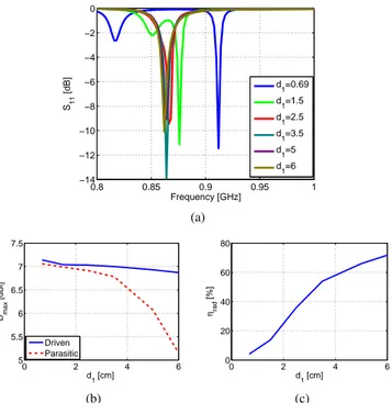
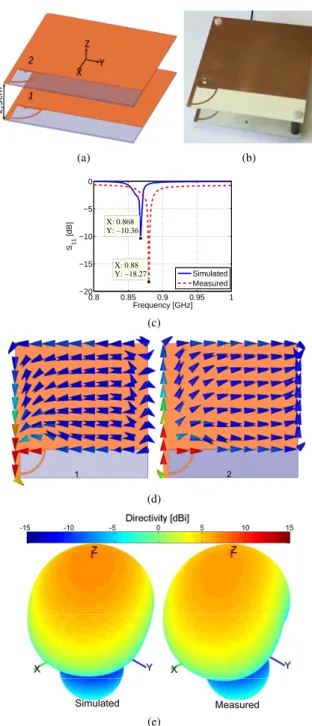
0.69cm to 6cm. Fig. 3(a) shows the effect of the inter-element distance on the resonance frequency. We note that for very small distances, the resonance is shifted to 910M Hz and as the distance increases this resonance converges to the one of the unit-element. Fig. 3(b) shows the array directivity as a function of the distance. As it can be noticed, the driven array directivity is maximal for small distances and as the distance increases this directivity decreases. The parasitic (loaded) array directivity is close to the fully-driven one till 3.5cm where a negative resistance is required and neglecting this resistance significantly decreases the array directivity. As for the array efficiency, it increases as the distance increases (Fig. 3(c)). This is due to the decrement in the mutual coupling and the disturbance in the superdirectivity phenomena. Based on this study and as compromise between the antenna- directivity and efficiency, we optimized a two-element array for 868M Hz European RFID frequency band with an inter-element distance of 2.5cm(0.07λ) as shown in Fig. 4(a). In this array, the first element is excited while the second is loaded by 3.3pF . Fig. 4(c) shows the antenna simulated input reflection coefficient magnitude in dB. As it can be noticed, the antenna has a resonance at 868M Hz. Fig. 4(d) shows the antenna surface current distribution. The figure shows that the current on the two elements is out of phase which is the condition for having superdirectivity for very small inter-element distance. Fig. 4(e) shows the antenna 3D total directivity radiation pattern. The figure demonstrates a directive pattern with a directivity of 7dBi toward z-axis. This directivity is 1.9dB greater than Harrington’s normal directivity limit [14] for an antenna with the same size factor (ka = 1.1). The HPBW in E (XoZ) and H
(a) (b) 0.8 0.85 0.9 0.95 1 −8 −6 −4 −2 0 X: 0.862 Y: −6.129 Frequency [GHz] S11 [dB] X: 0.881 Y: −6.301 Simulated Measured (c) 100.0 93.3 86.7 60.0 40.0 13.3 26.7 33.3 53.3 46.7 20.0 66.7 73.380.0 6.7 0.0 Jsurf [A/m] (d) Simulated Measured (e)
Fig. 1. The unit-element simulated and measured parameters. (a) Geometry and dimensions, (b) fabricated prototype, (c) input reflection coefficient magnitude in dB, (d) surface current distribution and (e) 3D total directivity radiation pattern. −5 5 15 30 210 60 240 90 270 120 300 150 330 180 0 θ [°] Directivity [dBi] Simulated Measured (a) −5 5 15 30 210 60 240 90 270 120 300 150 330 180 0 θ [°] Directivity [dBi] Simulated Measured (b)
Fig. 2. The unit-element simulated and measured 2D total directivity radiation pattern. (a) E plane and (b) H plane.
Due to the current opposition, the antenna presents a radiation efficiency of 43.4%.
A prototype of the antenna was fabricated and measured (Fig.
0.8 0.85 0.9 0.95 1 −14 −12 −10 −8 −6 −4 −2 0 Frequency [GHz] S11 [dB] d 1=0.69 d 1=1.5 d 1=2.5 d1=3.5 d1=5 d1=6 (a) 0 2 4 6 5 5.5 6 6.5 7 7.5 Dmax [dBi] d 1 [cm] Driven Parasitic (b) 0 2 4 6 0 20 40 60 80 ηrad [%] d 1 [cm] (c)
Fig. 3. Parasitic two-element array parameters as a function of the inter-element distance. (a) simulated input reflection coefficient magnitude in dB, (c) total directivity, and (c) radiation efficiency.
4(b)). Fig. 4(c) shows the antenna measured input reflection coefficient magnitude in dB. The measured resonance is at 880M Hz (a shift of 1.4% compared to the simulation). The antenna measured 3D total directivity radiation pattern at the resonance is given in Fig. 4(e). The measured directivity is
6.5dBi. The HPBW in E and H planes are respectively 95.6o
and 84o and FBR is 6.7dB (Fig. 5). The antenna radiation
efficiency measured in a reverberation chamber is about 40%.
IV. PLANARARRAYDESIGN
Four elements of the precedent parasitic array are integrated
in 2× 2 planar array as shown in Fig. 6(a). The spacing
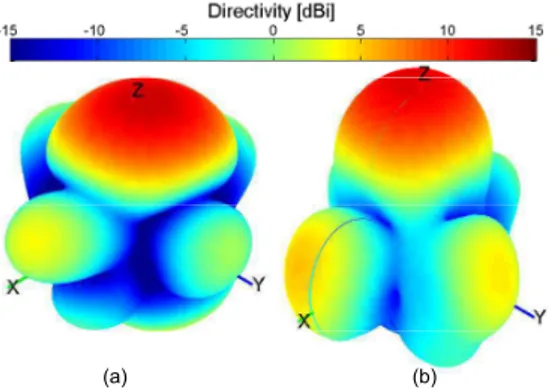
between the elements d (calculated between the excitation ports) is changed from 12cm to 30cm. Fig. 6(c) shows the mutual coupling as a function of the distance. As expected, the figure shows a higher coupling for small separations and as the distance increases the coupling decreases. Fig. 6(e) shows the antenna maximum directivity as a function of the distance. As the distance increases the coupling effect decreases and the achieved directivity increases till it reaches its maximum value around 0.8λ where it starts decreasing again. As for the antenna efficiency, as the distance increases it decrease (Fig. 6(f)). This is mainly due to the lost of the superdirectivity for small distances (superdirectivity is achieved by a current opposition on the two unit-elements (Fig. 4(d)) which cancels the antenna radiation in some directions and hence reduces its efficiency). Finally, Fig. 7 shows the 3D total directivity
radiation pattern for a distance of 26cm≈ 0.75λ. The achieved
directivity is 12.6dBi, and the radiation efficiency is 41%. The
HPBW in E (XoZ) and H (YoZ) planes are respectively 37o
and 35o and FBR is 8.9dB and the Side Lobe Level (SLL) is
(a) (b) 0.8 0.85 0.9 0.95 1 −20 −15 −10 −5 0 X: 0.868 Y: −10.36 Frequency [GHz] S11 [dB] X: 0.88 Y: −18.27 Simulated Measured (c) 1 2 (d) Simulated Measured (e)
Fig. 4. Two-element array with 2.5cm spacing simulated and measured parameters. (a) Geometry and dimensions, (b) fabricated prototype, (c) input reflection coefficient magnitude in dB, (d) surface current distribution and (e) 3D total directivity radiation pattern.
A prototype of the antenna was fabricated and measured (Fig. 6(b)). A power divider from Mini-Circuits [15] and UFL cables are used for the feeding system. Fig. 6(d) shows the antenna with the feeding system measured input reflection coefficient magnitude in dB. As it can be noticed, the resonance frequency is always at 879M Hz. It can also be noticed that the feeding system introduces a loss of about 1.5dB. This loss is due to the UFL cable, the power divider and the coaxial connections. The antenna directivity given in Fig. 6(e) shows the same trend as in the simulation. The antenna measured 3D total directivity for a distance of 26cm is in a good agreement with the simulated one (Fig. 7). The measured directivity is 12.1dBi. The HPBW
−5 5 15 30 210 60 240 90 270 120 300 150 330 180 0 θ [°] Directivity [dBi] Simulated Measured (a) −5 5 15 30 210 60 240 90 270 120 300 150 330 180 0 θ [°] Directivity [dBi] Simulated Measured (b)
Fig. 5. Two-element array with 2.5cm spacing simulated and measured 2D total directivity radiation pattern. (a) E plane and (b) H plane.
in E and H planes are respectively 39.4o and 33.8o and FBR
is 18.8dB (Fig. 8). The antenna reveals a measured radiation efficiency (also in a reverberation chamber) of about 39.8% after compensating the losses in the feeding system.
In all cases, the small difference between the simulated and measured results is due to the measurement environment (the connector, the excitation cable, ..), the measurement incertitude and the tolerance on the reference antennas’ parameters namely directivity for radiation pattern measurement and radiation efficiency in the efficiency measurement.
(a) (b) 0.3 0.4 0.5 0.6 0.7 0.8 −45 −40 −35 −30 −25 −20 −15 Sij [dB] d/λ S 12 S 13 S 14 (c) 0.8 0.85 0.9 0.95 1 −12 −10 −8 −6 −4 −2 0 X: 0.879 Y: −11.41 Frequency [GHz] S11 [dB] d/λ=0.35 d/λ=0.46 d/λ=0.58 d/λ=0.75 (d) 0.3 0.4 0.5 0.6 0.7 0.8 7 8 9 10 11 12 13 Dmax [dBi] d/λ Simulated Measured (e) 0.3 0.4 0.5 0.6 0.7 0.8 35 40 45 50 55 60 65 ηrad [%] d/λ Simulated Measured (f)
Fig. 6. Planar array simulated and measured parameters as a function of the separation. (a) Geometry, (b) fabricated prototype, (c) mutual coupling, (d) input reflection coefficient magnitude in dB, (e) total directivity and (f) radiation efficiency.
(a) (b)
Fig. 7. Planar array 3D total directivity radiation pattern for d=26cm. (a) Simulated and (b) measured.
−5 5 15 30 210 60 240 90 270 120 300 150 330 180 0 θ [°] Directivity [dBi] Simulated Measured (a) −5 5 15 30 210 60 240 90 270 120 300 150 330 180 0 θ [°] Directivity [dBi] Simulated Measured (b)
Fig. 8. Planar array 2D total directivity radiation pattern for d=26cm. (a) E plane and (b) H plane.
V. CONCLUSION
In this paper, a two-element parasitic superdirective an-tenna array was designed. These array was later integrated in
2× 2 planar antenna array. A parametric analysis on the
inter-element distance revealed the tradeoffs between the antenna dimensions, directivity and efficiency. For an inter-element
distance of 26cm and for total dimensions of 34×34cm2a total
directivity of 12.6dBi and radiation efficiency of 41% were achieved. This antenna is significantly smaller than classic arrays with the same directivity.
ACKNOWLEDGMENT
The authors would like to thank Mr. Jérôme Sol from IETR UMR CNRS 6164- INSA de Rennes for all the time he dedicated to the measurements presented in this manuscript.
REFERENCES
[1] E. E. Altshuler, T. H. O’Donnell, A.D. Yaghjian, and S. R. Best, "A
Monopole Superdirective Array", IEEE Transactions on Antennas and
Propagation, vol. 53, no. 8, pp. 2653-2661, August 2005.
[2] T. H. O’Donnell, and A. D. Yaghjian, "Electrically Small Superdirective
Arrays Using Parasitic Elements", IEEE Antennas and Propagation
Society International Symposium 2006, pp. 3111,3114, 9-14 July 2006. [3] S. Lim, and H. Ling, "Design of Electrically Small Yagi Antenna",
Electronics Letters, vol. 43, no. 5, pp. 3-4, 1 March 2007.
[4] A. D. Yaghjian, T. H. O’Donnell, E. E. Altshuler, and S. R. Best
"Electrically Small Supergain End-Fire Arrays", Radio Science, vol. 43,
2008.
[5] P. Sharma, D. Arora, and H. Gupta, "Designing Superdirective Patch
An-tenna Array Using Metamaterial", International Journal of Engineering
Research & Technology (IJERT), vol. 1, issue 8, October 2012.
[6] O. S. Kim, S. Pivnenko, and O. Breinbjerg, "Superdirective Magnetic
Dipole Array as a First-Order Probe for Spherical Near-Field An-tenna Measurements", IEEE Transactions on AnAn-tennas and Propagation,
vol. 60, no. 10, pp. 4670-4676, October 2012.
[7] B. Sentucq, A. Sharaiha, and S. Collardey, "Superdirective Compact
Parasitic Array of Metamaterial-Inspired Electrically Small Antenna",
International Workshop on Antenna Technology (iWAT), pp. 269,272, 4-6 March 2013.
[8] M. Pigeon, A. Sharaiha, and S. Collardey, "Miniature and Superdirective
Two Elements Endfire Antenna Array", 8th European Conference on
Antennas and Propagation (EuCAP 2014), pp. 3553-3556, 6-11 April 2014.
[9] A. Haskou, A. Clemente, A. Sharaiha, C. Delaveaud, S. Collardey, and L. Rudant, "A Parasitic Three-Element Superdirective Electrically Small
Antenna Array, Proceedings of Ninth European Conference on Antennas
and Propagation (EuCAP 2015), pp. 1-4, 12-17 April 2015.
[10] A. Clemente, M. Pigeon, L. Rudant, and C. Delaveaud, "Design of a
Super Directive Four-Element Compact Antenna Array Using Spherical Wave Expansion, IEEE Transactions on Antennas and Propagation,
vol. 63, no. 11, pp. 4715-4722, November 2015.
[11] A. Haskou, A. Sharaiha, and S. Collardey, "Design of Small Parasitic
Loaded Superdirective End-Fire Antenna Arrays", IEEE Transactions on
Antennas and Propagation, vol. 63, no. 12, pp. 5456-5464, December 2015.
[12] ANSYS HFSS, Pittsburg, PA 15219, USA.
[13] G. Le Fur, C. Lemoine, P. Besnier, A. Sharaiha, "Performances of
UWB Wheeler Cap and Reverberation Chamber to Carry Out Efficiency Measurements of Narrowband Antennas", IEEE Antennas and Wireless
Propagation Letters, vol. 8, pp. 332,335, 2009.
[14] R. F. Harrington, "On the Gain and Beamwidth of Directional
Anten-nas", IRE Transactions on Antennas and Propagation, pp. 219-225, July
1958.