HAL Id: hal-01699842
https://hal.inria.fr/hal-01699842
Submitted on 2 Feb 2018
HAL is a multi-disciplinary open access
archive for the deposit and dissemination of
sci-entific research documents, whether they are
pub-lished or not. The documents may come from
teaching and research institutions in France or
abroad, or from public or private research centers.
L’archive ouverte pluridisciplinaire HAL, est
destinée au dépôt et à la diffusion de documents
scientifiques de niveau recherche, publiés ou non,
émanant des établissements d’enseignement et de
recherche français ou étrangers, des laboratoires
publics ou privés.
Generic Object Discrimination for Mobile Assistive
Robots using Projective Light Diffusion
Panagiotis Papadakis, David Filliat
To cite this version:
Panagiotis Papadakis, David Filliat. Generic Object Discrimination for Mobile Assistive Robots using
Projective Light Diffusion. WACVW 2018 : IEEE Winter Conference on Applications of Computer
Vision, Workshop CV-AAL - Computer Vision for Active and Assisted Living, Mar 2018, Reno, United
States. pp.1-9, �10.1109/WACVW.2018.00013�. �hal-01699842�
Generic Object Discrimination for Mobile Assistive Robots
using Projective Light Diffusion
Panagiotis Papadakis
1, David Filliat
21
IMT Atlantique Bretagne/Pays de la Loire, LabSTICC UMR 6285, team IHSEV, Plouzan´e, France
2ENSTA ParisTech, U2IS, Inria FLOWERS team, Universit´e Paris-Saclay, Palaiseau, France
Abstract
A number of assistive robot services depend on the clas-sification of objects while dealing with an increased volume of sensory data, scene variability and limited computational resources. We propose using more concise representations via a seamless combination of photometric and geomet-ric features fused by exploiting local photometgeomet-ric/geometgeomet-ric correlation and employing domain transform filtering in or-der to recover scene structure. This is obtained through a projective light diffusion imaging process (PLDI) which al-lows capturing surface orientation, image edges and global
depth gradients into a single image. Object candidates
are finally encoded into a discriminative, wavelet-based de-scriptor allowing very fast object queries. Experiments with an indoor robot demonstrate improved classification per-formance compared to alternative methods and an overall superior discriminative power compared to state-of-the-art unsupervised descriptors within ModelNet10 benchmark.
1. Introduction
In the development of assistive service robots for indoor operation, the capability to detect and recognize generic 3D objects is indispensable. The fact that a number of robot skills such as manipulation, semantic mapping and naviga-tion are directly dependent on this capability can largely ex-plain its prevalent role, which is further promoted by the ad-vent of sensors that provide synchronized photometric and geometric (RGB Color and Depth) information. RGB-D sensors have boosted progress in the above research fields as they enable the parallel use of 3D geometric and 2D im-age processing for improving object perception.
The challenges in object perception are strongly related to the object classes that are expected to be encountered as well as their surroundings. For instance, in the case of robotic manipulation scenarios object texture is highly in-formative of the object class while sensor noise is reduced due to small object/sensor distance and stable environment
lighting. Works that are concerned with object perception for robotic manipulation [1, 2] may frequently discount ef-ficiency at the benefit of discriminative power through sep-arate treatment of color and geometry.
Conversely, in the case of object perception during map-ping [3, 4] shape becomes more discriminative than texture due to the increased sensor/object distance while lighting conditions can vary considerably. As a result, processing the entire volume of sensory data may hinder a timely robot response to certain object classes, therefore exploiting both color and geometry is generally more computationally re-stricting. The issue had been early recognized, neverthe-less, more recent works [5] suggest that real-time as well as reliable object perception remains challenging.
Here we are concerned with the latter problem, namely, detection and classification of objects of interest in the sur-roundings of a robot during indoor mapping. The problem is conceptually related to numerous works in the domain of computer vision, e.g. [6],[7] and [8]. Nevertheless, relevant works with a clear robotic scope as e.g. in [9] are relatively sparse. This is largely due to the low resolution of RGB-D data within a narrow field-of-view (FOV) and increased noise which restricts the application of more elaborate sig-nal processing as it impacts real-time performance.
Some works such as [10], [11], seek to alleviate the ef-fect of narrow FOV by employing RGB-D based SLAM in order to stitch together the corresponding object views. Contrarily to such approaches, our objective is to reduce the necessity for constructing global metric-scale maps and in-stead primarily rely on semantic maps where even partially observed objects are used as landmarks. Therefore, our starting point for object perception is to treat single RGB-D scene frames rather than complete 3RGB-D object reconstruc-tions. In corroboration to this, the large-scale experiments presented in [8] or [12] clearly suggest that view-based methods generally outmatch complete 3D-based shape de-scription methodologies.
Finally, works which are based on learning
dictionaries/Bag-of-Words [13], [14] or deep neural
studying the generalization capability of our representation and derive a fair evaluation among alternative represen-tations, without requiring a large training dataset. In this work we are strictly focused on the design of informative shape representations and descriptions exploitable in a robotic context, not on potential fine-tuning/training that could be applied in the sequel regardless of the underlying representation. Characteristically, the latest evolution of state-of-the-art PANORAMA representation [16] intro-duced by [17] which couples its discrimination capacity with training in the form of convolutional neural networks was shown to outperform the state-of-the-art on synthetic 3D object discrimination.
The main contribution claimed by this work is a novel representation termed as projective light diffusion image (PLDI) which can encode surface orientation, depth as well as photometric characteristics that can be subsequently cap-tured in concise and efficient to compute shape descriptors. Here, we perform proof-of-concept experiments by expand-ing PLDIs into a set of wavelet-based features by evolvexpand-ing earlier work [16], originally designed for generic 3D ob-ject discrimination. This results in a new descriptor based on PLDI that allows faster and more discriminative object matching when compared to competitive state-of-the-art ap-proaches in common indoor scenarios, combined with a re-markably low feature dimensionality. This makes it par-ticularly suited for robotic applications which often impose considerable constraints in terms of computational and stor-age capacity. Through the proposed approach, our robot was able to reliably discriminate various real objects using a total of only #4 synthetic object templates per class.
We organize the remainder of the article as follows. In section 2 we unfold our approach for fusing photomet-ric with geometphotomet-ric information to compensate for noisy or missing sensor readings. In section 3 we detail the extrac-tion of projective light diffusion images and subsequently in sections 4 and 5, the object candidate segmentation and fea-ture extraction/matching components of our methodology, respectively. Finally, section 6 evaluates the performance of the complete framework in experiments with a mobile robot and compares against related alternatives.
2. Filtering
Conventional RGB-D sensors provide 15/30 fps at a maximum resolution of around 1 Mpixel and depth images that are subject to intense noise levels. To alleviate the im-pact of noise in the sensory data we adopt an approach to fuse color with depth information into a single representa-tion. Our motivation for color and depth fusion is two-fold; (i) to exploit local correlation existing between image inten-sities and 3D geometry for noise filtering and edge preser-vation and (ii) reduce the total processing time by subse-quently treating a single fused representation for feature
ex-traction instead of separate color and depth descriptors. In choosing a fusion scheme, we first note that raw depth data are subject to considerably higher levels of
noise in comparison to color [18]. This is mainly
be-cause the acquired depth images often contain large ar-eas of invalid/unknown depth pixel values induced by non-reflective/transparent surfaces or limited FOV. This suggests exploiting the the 3-channel color image as a means for re-covering the 1-channel depth information.
Towards this goal, we use the 4-channel image of an RGB-D frame as a filtering guide and employ three Gaus-sian kernels that operate within the color, depth and the 2D image domain space respectively. The operation resembles that of the conventional bilateral filtering but differentiates with respect to the input and desired output image, known as joint bilateral filtering (JBF) [19]. We employ JBF by treating the RGB-D image as a guide in order to obtain a re-constructed depth and ignore pixels with invalid depth val-ues which would mislead filtering.
Let I, J denote the raw 3-channel RGB image and 1-channel depth (Fig. 1 (a)) respectively, of a given RGB-D
frame and Gd, Gi, and Gj the selected domain, color and
depth Gaussian kernels respectively. The cross filtered
im-age ˜J(Fig. 1 (b)) is obtained as:
˜ Jp= 1 Cpq∈Ω|∃J
∑
q Gd(||p − q||)Gi(Ip− Iq)Gj(Jp− Jq)Jq (1) Cp=∑
q∈Ω|∃Jq Gd(||p − q||)Gi(Ip− Iq)Gj(Jp− Jq)where p, q ∈ Ω denote 2D pixel locations in the image
do-main Ω ⊂ Z2∗, where Z∗denotes the set of non-negative
in-tegers and Cpis the normalization denominator.
Multiple iterations of eq. (1) are possible in order to ex-tend depth reconstruction until there are no missing depth values, however this increases the risk of physically con-necting disjoint surfaces as a consequence of smoothing.
To avoid the direct computation of eq. (1) which op-erates in 6D space we follow the idea of Domain
Trans-form filtering (DTF) presented in [20]. The core
no-tion underlying DTF resides in isometrically transforming the domain of a multi-channel image into a 1D domain wherein geodesic distances in the original image are pre-served within the transformed signal. Performing filtering of the transformed image using a 1D kernel along vertical and horizontal passes rather than using kernels in the orig-inal space, reduces the computational complexity of filter-ing to linear time by encodfilter-ing the original kernel param-eters within the domain transform (cf. p.4 in [20]). For completeness, we recall the central equation used for per-forming the DFT ct(.) of the multichannel RGB-D image S
where Sq= (Iq, Jq) ∈ {[0, 255]3× R+}, namely:
ct(u) =
Z u
0
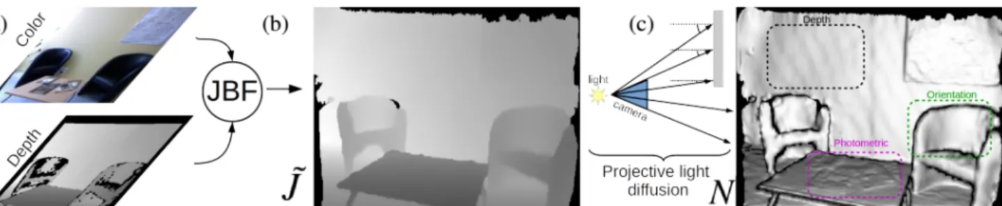
Figure 1. Filtering/fusion pipeline; (a) Raw depth image and RGB image, (b) reconstructed depth image and (c) projective light diffusion image. Emergent depth, photometric and surface orientation scene characteristics captured by PLDI are partially highlighted for emphasis (best viewed in color).
where u corresponds either to the horizontal or the vertical
image dimension depending on the filtering pass and |.|1
is the L1norm. Although more elaborate RGB-D filtering
schemes such as [21] or [22] could be considered we ad-vocate the use of JBF via DTF as being more suited for real-time applications without explicitly requiring a paral-lelized implementation. Furthermore, as our final goal is to classify 3D objects rather than recognize particular in-stances, recovering very subtle surface details is secondary if the main discriminative features of the observed objects are captured.
3. Projective Light Diffusion Image Extraction
Our shape description methodology relies mainly on the use of information about the surface orientation distribution of objects. The next step therefore amounts to the compu-tation of the 3D surface oriencompu-tation that is encoded within the filtered depth image. The procedure consists of three stages: (i) backward projection of depth pixels belonging to
˜
Jto the 3D coordinate frame of the sensor, (ii) computation
of the 3D surface orientation tensor for the total set of re-projected points within the coordinate frame of the sensor and (iii) light source emulation at the center of the camera.
Letting K be the camera matrix, we obtain the total set
of 3D points as P = {v ∈ R3|v = K−1[p
x, py, ˜Jp]T, p ∈ Ω}
and the 3D surface orientation vectors as np = e2, where
e0, e1, e2correspond to the orthonormal eigenvectors of the
local point density (within a maximum radius rmax), sorted
in decreasing order. Fig. 1 (c) shows the output of this process denoted as image N, obtained by remapping in
grayscale the cosine of the angle between normal vector np
and the camera projection ray vp passing through the
re-spective pixel, namely:
Np= |np· vTp|/|vp| (3)
The obtained image N is hence the equivalent of the
diffu-sionreflection component of light reflection models where
in our case the light source coincides with the camera. A qualitative comparison among initial raw depth/color data and corresponding PLDI reveals a number of
advan-tages. Firstly, we note that previously unknown surface ar-eas (mainly located in the interior of the sofas’ boundaries, see Fig. 1 (a)) have now been largely recovered by using color and depth while preserving edge information. More importantly, new details originating from the image domain are emerging within the PLDI in predominantly planar areas (tabletop magazines, wall poster, floor tiles, wooden shelf-side, blankets, see Figs 2 and 1 (c)). And finally, a new feature emerges due to the use of the projective light source emulation. In detail, while the 3D orientation of a surface itself does not convey any depth information locally, never-theless, depth characteristics emerge globally for extended surfaces (mainly noticeable along walls in the provided ex-amples and the double beds) as a result of the increasing intersection angle between the emulated light rays and the surface normals. PLDI is hence capable of jointly encoding surface orientation, depth and photometric features which proves advantageous is object classification compared to us-ing separate images (see section 6).
4. Object Clustering and Segmentation
To segment candidate objects we impose a set of con-straints that characterize (a) indoor scenes, (b) the robot sensing configuration and (c) the sensory data, following a paradigm similar to [9], [3] that assume moderate levels of clutter in terms of object/background interference. Our goal is to discriminate well separated from overly occluded candidates and attempt to recognize only the former. The latter could be treated at the decision level, e.g. through
ac-Figure 2. Example RGB-D scenes and corresponding PLDI im-ages. Photometric features emerge along the floor (tiles), library (wood texture), poster et blanket covers. Depth gradients are no-ticeable along the wall and the double beds.
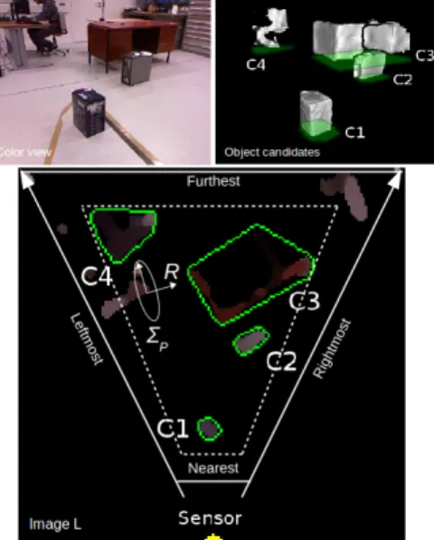
Figure 3. Object clusters detection and contours extraction. Den-sity estimation is performed on image L after aggregating the point projections to the floor plane. The sensory area corresponds to the interior of the dashed polygon.
tive perception in order to resolve the respective occlusion, which is beyond our scope here. On the contrary, clutter due to sensing noise is more amplified within our experi-mental scenario due to the variability of lighting conditions and extended perceptual range (see Sec. ??).
Indoor scene constraint We assume the existence of a dominant 2D plane which corresponds to the floor, serv-ing as the lower boundary that splits in half the total 3D space and retains only parts that lie above. In practice, this plane corresponds to the configuration space used for path-planning and can be easily obtained beforehand in the case where the sensor pose is fixed. For the case where the sen-sor pose changes with respect to the floor, we can update the parameters of the floor plane for every newly acquired 3D point cloud using robust estimation algorithms such as
Random Sample Consensus(RANSAC).
Sensing constraints The robot sensing configuration is used to impose the remaining boundaries of the total sen-sory region. Two planes orthogonal to the floor are set for the furthest and nearest permissible distance from the sen-sor. Another two planes orthogonal to the floor that pass from the center of the sensor are used to the set the limits of the leftmost and rightmost permissible angles, set according to the corresponding leftmost and rightmost rays that em-anate from the camera center. Setting an uppermost plane boundary is not required since the sensor is constantly di-rected towards the ground. The imposed limits are depicted in Fig. 3 for a top-down view of an example scene.
Data-driven constraints The set of RGB-D points Ps⊂
P that lie within the constrained sensory area are
subse-quently aggregated by projecting them on the 2D floor
Figure 4. Perspective warping of segmented object from the
pro-jection plane πodefined between the actual object pose and camera
coordinate frame, to the globally selected projection plane πf.
plane, which produces an image denoted as L ∈ Z2∗which is
used as the domain where clustering is performed.
To obtain a set of object candidates, we apply an adap-tive Parzen window density estimator using a 2D Gaussian
kernel GPon image L and next retain only those pixels with
density higher than a threshold in order to filter out noisy measurements or small disjoint surfaces. Essentially, the chosen kernel accounts for the measurement error distribu-tion of the camera sensor and depends on the angle between the pixel’s camera ray and the camera’s principal direction.
The covariance matrix ΣP of GP is therefore obtained as
ΣP= RTΣR, where R denotes the rotation matrix and Σ the
general measurement error covariance [18] (see Fig. 3). The retained pixel locations within L are then grouped to-gether by using conventional contour detection and border following. Fig. 3 shows an instance of a scene and the re-spective clustering (the exclusion of object clusters that are off the sensory boundaries can be observed in image L).
In the sequel, we perform a coarse ray tracing scan to determine if a cluster is potentially occluded and exclude such clusters in order to reduce classification errors. We perform ray tracing in the image L for obtaining the pixels along a projection ray and for each such pixel assert whether it lies in the interior of an object contour. In the example of Fig. 3, clusters C3,C4 are finally excluded as other contours in the foreground intersect the corresponding rays.
Finally, we impose size constraints on the surface area within the contour of each cluster, i.e. the size of the 2D object footprint and the length of the contour and discard clusters that are excessively large or small. These thresholds are set according to the expected object classes.
Object clusters in image L that successfully pass all the aforementioned tests are then used to segment the corre-sponding parts within image N that are going to be used for feature extraction. The segmentation is performed by keep-ing only the 3D surface which lies within the boundaries of the respective contour of the footprint of each object, by
applying depth culling within the depth image ˜J.
As a final step, it is necessary to account for distortions that alter the projected shape of an object depending on the viewpoint. To address this issue, we choose a common
pro-jection plane πf that lies in front of the camera at the center
ob-ject image so that its actual proob-jection plane πomatches the
frontal plane πf using the respective homography (Fig. 4
illustrates a characteristic example). The πoplane
parame-ters are obtained using the distance and angle between the camera frame and the centroid of the object.
A number of points are worth commenting after the com-pletion this stage. In particular, the fact that an object may
still be perspectively distorted after warping to πf is not
problematic, since that distortion will be the same for all objects regardless of the viewpoint. In addition, the applied warping ensures that the distance from the sensor to the ob-ject has no effect on the scale of the PLDI of the obob-ject candidate. This means that if an object is observed from a
distance which is further than the distance of πf from the
sensor, then warping will have an upscaling effect on the initial PLDI and conversely, in the case where the object is observed from a nearest distance. Finally, it is true that while warping can account for the perspective distortion in-duced by the viewpoint, it does not warp the initial 3D rays
vpused in eq. (3), to their new poses. Reapplying eq. (3)
after warping, however, did not seem to have any noticeable impact in the resulting discrimination between objects.
5. Features Representation
Up to this point, we have segmented object candidates in the form of PLDIs which should be subsequently en-coded through a corresponding feature-based description. Towards this direction, we integrate ideas from the state-of-the-art unsupervised 3D shape descriptor PANORAMA [16]. PANORAMA was originally designed for describ-ing entire 3D polygonal models, it employs full 3D pose normalization, cylindrical projection extraction of separate depth and orientation images and a corresponding series ex-pansion in space/time domain.
To accommodate differences existing with the current application domain, a number of adaptations were required. In detail, instead of having three orthogonal panoramic pro-jections of an object aligned with its principal axes, here we only dispose a single view of the object that has been nor-malized to match the canonical projection plane. Hence, in-stead of relying on global object matching we rely on partial object matching via a single viewpoint since (as mentioned in Section 1) we seek to reduce the necessity for metric mapping and also because complete 3D object inspection is often impossible in reality. Most importantly, instead of us-ing separate depth and surface orientation images as is done in PANORAMA, here we only use the PLDI image which is capable of encoding both modalities. We do this by retain-ing a wavelet-based decomposition of PLDI which is char-acterized by a high discriminative power/dimensionality ra-tio and a linear computara-tional complexity through the use of the fast wavelet transform.
Letting N : Z2
∗→ [0, 1] be the segmented and warped
PLDI of an object, we compute the corresponding 2D Dis-crete Wavelet Transform (DWT) expressed as:
Wφ( j 0, m, n) = 1 √ 2B · 2B· 2B−1
∑
u=0 2B−1∑
v=0 N(u, v) · φj0,m,n(u, v) (4) Wψ( j, m, n) =√ 1 2B · 2B· 2B−1∑
u=0 2B−1∑
v=0 N(u, v) · ψj,m,n(u, v) (5)where m, n ∈ [0, 2B−1], B is the sampling bandwidth, j ≥ j0
denotes the scale of the multi-level DWT, j0 is the
start-ing scale, φj0,m,n, ψj,m,nare the scaling and wavelet
func-tions respectively and N(u, v) is the final segmented pro-jective light diffusion image of a single object (e.g. Fig.
4 right). We compute a full-scale DWT of log22B
lev-els, therefore j = 0, 1, ..., log22B − 1. The Wφ( j0, m, n)
approximation/scaling coefficients correspond to the
low-pass subband of the transform at the starting scale j0while
the Wψ( j, m, n) detail/wavelet coefficients correspond to the
vertical, horizontal and diagonal subbands. We take the absolute value of the coefficients and normalize to their
unit L1norm, which are now denoted as ˜Wφ( j0, m, n) and
˜
Wψ( j, m, n) (see [16] for further details).
Finally, we evaluate a set of central moments from the obtained coefficients image, namely, the mean, standard de-viation and skewness, for each distinct sub-band and level
j> j0of the transform (for the scale at the smallest
resolu-tion j = j0we keep the respective scalar values for the
scal-ing and detail coefficients). The total procedure gives a final
feature vector f of dimensionality 3 × 3 × (log22B − 1) + 4.
The distance d(f1, f2) between two feature vectors f1, f2is
evaluated by using the Canberra distance and object queries are appointed the class of the nearest neighbor from the sorted list of retrieved objects.
The main differences between the newly proposed PLDI-based descriptor and the original PANORAMA descriptor are summarized in the following table.
TABLE I. PLDI vs PANORAMA
PLDI PANORAMA Partial 3D objects X -Dimensionality 58 15948 Features (Depth/Orientation/Photometric) X/X/X
X/X/-6. Experiments
To evaluate our approach we initially performed exper-iments in realistic conditions, elaborating on its effective-ness as well as efficiency aspects. Finally, we compare our method against state-of-the-art, unsupervised shape-based descriptors, both in realistic conditions as well as within a large-scale dataset and show that a significant advantage in discriminative power is attained.
6.1. Context
The experiments were conducted for ROMEO2 project [23] which is a French National Project coordinated by SoftBank Robotics, formerly known as Aldebaran. The project aspires developing a state-of-the-art humanoid as-sistant robot for frail people and more generally for people with reduced mobility which can assist them in common daily tasks. This is made possible by developing advanced cognitive and operational skills, including, social human-robot interaction, audiovisual sensing and object discovery and manipulation.
Among the various scenarios of interest, object percep-tion is decomposed into two stages treated independently wherein the robot is primarily capable of perceiving and classifying large objects of interest placed on the ground (such as boxes, small and medium furniture, pots, etc) dur-ing navigation and secondarily, objects of interest lydur-ing on a table. The first stage is mainly exploitable for semantic mapping of the environment while the second is more per-tinent to a subsequent object manipulation.
The following sections summarize the series of exper-iments that were performed in addressing the first stage, namely object discovery and classification of large objects using the Kinect v1 sensor by a mobile robot.
Ground-Truth The ground-truth used for the evaluation with a real robot is divided into two sets/splits of objects. The first set contains 3D object instances collected manu-ally from the internet which belong to the classes of interest. We selected classes of 3D objects that were commonly en-countered during indoor robot navigation and of fixed car-dinality (4 objects per class). For each object, we then sim-ulate a ring of M viewpoints distributed at regular angular intervals around its centroid, at a fixed distance from the ob-ject (2 meters) and a camera pose equivalent to the configu-ration of the actual robot sensing system. In this manner, all
objects are projected using the same reference plane πf.
Be-fore projection, objects are placed along their expected ori-entation in the real world following a semi-automatic pre-processing step. Thus we finally obtain a synthesized set of
M PLDIs per object by simulating frame acquisitions of a
Kinect sensor.
The second set contains the real 3D objects that were en-countered by our mobile robot during exploration and that is used for testing the performance. In other words, whenever a real 3D object was segmented and deemed as a candidate as explained in Section 4, its corresponding PLDI descriptor is matched against all PLDI descriptors of the first set and it is appointed the class of the retrieved nearest neighbour.
The objects of the second set were encountered by a in-door robot equipped with an Kinect v1 sensor remotely op-erated in the interior of an office building. The visited areas included corridors, offices, lounge halls and a workshop, altogether characterized by a wide range of lighting
condi-tions and scene/object configuracondi-tions. Excluding corridors that were characterized by interior lighting and minimal ob-ject presence, all remaining areas where most obob-jects were located were illuminated by strong exterior daylight thereby degrading the quality of depth acquisition in several cases. Finally, we note that since we match real 3D objects against synthetic 3D objects this induces a relatively high intra-class variance.
Table II summarizes the values used for the prominent parameters related to the evaluation in terms of the proposed method setting and the experiment.
TABLE II. Parameter setting & Experiment
Radii Gd, Gi, Gj, rmax 12(px), 10(RGB), 4(cm), 4(cm)
Wavelet bandwidth B, basis functions 64(px), Daubechies-D8 Explored area 1485 (m2)
Number of classified objects 31 Number of segmented object candidates 1716
Stand-alone evaluation Initially, we compare the dis-criminative power in using the proposed projective light dif-fusion image N (abbreviated as PLDI) against a
conven-tional depth image ˜J(abbreviated as Depth), while keeping
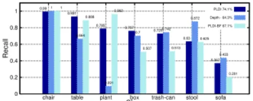
identical all other components of our methodology. We use the recall performance measure, namely, the ratio of true positives to the sum of true positives and false negatives. The results are shown in the diagram of Fig. 5 for each object class together with the macro-averaged performance. The performance benefit by using PLDI against depth images is evident across the majority of object classes with an overall gain in the order of 9.8%. Interestingly, this re-sult contrasts previous experiments in [16] (cf. page 11, Fig. 12) wherein depth images were consistently found superior to surface orientation images in the context of large-scale, content-based 3D model retrieval. We believe that the ad-vantage of PLDI is mainly attributed to the fact that it is en-riched with photometric information due to the use of JBF, as opposed to pure surface orientation images.
To evaluate this hypothesis, we tested performance by substituting the JBF with an equivalent (same kernel) bi-lateral filter (BF) which is applied to the raw depth image
J (abbreviated as PLDI-BF). From Fig. 5, we can attest
that classification performance is indeed favoured through
0 0.2 0.4 0.6 0.8 1
chair table plant box trash-can stool sofa
Recall Class PLDI 74.1% Depth - 64.3% PLDI-BF 67.1% 0.99 0.931 0.785 0.757 0.725 0.63 0.367 1 0.664 0.091 0.7 0.742 0.872 0.433 1 0.888 0.962 0.507 0.513 0.625 0.201
Figure 5. Performance comparison between proposed methodol-ogy (PLDI) against baseline alternatives (Depth, PLDI-BF)
the application of JBF and the integration of photometric information in all classes except the plant class. Instances belonging to the sofa class were overall the most difficult to perceive due to their surface material which severely de-graded depth acquisition from the sensor and propagated errors from reconstruction until shape description.
The overall superiority of PLDI is also consistently vali-dated in terms of macroscopic precision (ratio of true posi-tives to the sum of all posiposi-tives), as given in Table III.
TABLE III. Macro-averaged precision comparison
PLDI PDLF-BF Depth
Precision 75.3 % 65 % 67.1 %
In terms of efficiency, the overall framework enables real-time object classification using an optimized C++ implementation on a contemporary computer (Intel i7, 3.40GHz ×8). Table IV reports the average frame rate in Hz attained for the complete pipeline from raw data process-ing until classification, together with the efficiency gain that is possible for different levels of parallelization via multi-threading. Notably, real-time performance is feasible even without parallelization. In Table VI we report how ing time is on average partitioned among the main process-ing blocks of the entire pipeline. The most time-demandprocess-ing part corresponds to the PLDI extraction due to the com-putation of the eigenvector decomposition of local patches across the entire point cloud. As expected, feature match-ing is extremely efficient (around 1µs per comparison) due to its low dimensionality, that would still allow real-time queries from considerably bigger object repositories.
TABLE IV. Time performance # threads
1 2 4 6
Frames/sec 6.2 6.9 7.3 7.5
TABLE V. Timing ratios
RGB-D filtering 21%
PLDI extraction 38.6%
Clustering 19.8%
Feature extraction 20.5%
Matching 6e-6%
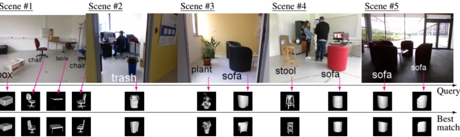
Finally, examples of the qualitative performance from various scenes of the experiments are illustrated in Fig. 6. In a number of cases (e.g. table, plant and stool), it is worth noting that despite the relatively reduced intra-class object similarity, the proposed approach is successful in ap-pointing the correct object label. The effect of strong exte-rior lighting can also be noticed (mainly for scenes #2 and #5) which was the most frequent cause of misclassification, nevertheless, the problem of missing depth can be signifi-cantly alleviated through the JBF application.
Comparison with other methods We have compared PLDI against state-of-the-art descriptors used in robotics and of computational efficiency similar to PLDI, namely,
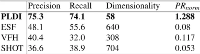
TABLE VI. Comparative evaluation of descriptors
Precision Recall Dimensionality PRnorm
PLDI 75.3 74.1 58 1.288
ESF 48.1 55.6 640 0.08
VFH 40.4 32.0 308 0.117
SHOT 36.6 38.9 704 0.053
Viewpoint Feature Histogram (VFH) [24], Ensemble of Shape Functions (ESF) [25] and Signature of Histograms of Orientations (SHOT) [26]. We use the implementations provided in PointCloudLibrary (PCL) and the suggested settings for all methods according to [27], namely, we first voxelize a point cloud to a grid of 0.01cm and set the ra-dius for normal vector computation needed for VFH and SHOT to 0.03cm. Descriptors are extracted off-line for each method for the synthetic dataset in the same mode as for PLDI, while during on-line detection and classification, we adopt the same object clustering and segmentation as de-scribed in Sec. ?? and obtain object labels using the near-est neighbour. To obtain a global descriptor and perform matching using SHOT, we follow [27] (cf. Section II) which uses the average of the set of keypoints as global descriptor
and then computes the sum of L1distances between
cen-troids and their respective standard deviations.
In Table VI we show the comparative performance in terms of macro-averaged precision and recall. We further evaluate the normalized descriptiveness of each method by taking into account their dimensionality. Equivalently to the evaluation within [28] (cf eq. (6)), we take the ratio of aver-age performance (here the averaver-age of precision and recall) to the total number of dimensions. This expresses the dis-criminative performance per descriptor dimension, which
we denote as PRnorm. Clearly, the proposed PLDI method
attains a considerable advantage against all compared meth-ods while achieving this with the lowest dimensionality. We attribute the performance gain of PLDI to certain important aspects. Relatedly, while there exists visual resemblance between the synthetic objects and those encountered in real-ity, there is no exact correspondence and therefore descrip-tor variance between the two domains is high. The quantita-tive results suggest that PLDI can capture more effecquantita-tively the discriminative object features compared to the other.
In addition, we believe that the other tested methods are not sufficiently robust to alleviate the extended range of sen-sor noise levels within the maximum permissible distance of our scenarios which is set to 4 meters and the considerably increased variation of sensing conditions due to exploration of different rooms. The fact that the average sensor-object distance within our experiments was 2.6 meters which is relatively higher than the implicitly assumed for the com-pared descriptors, shows that the PLDI can exploit more
Figure 6. Qualitative classification results using data association. First row; Examples scenes. Middle row; corresponding reconstructed PLDI of segmented objects. Bottom row; corresponding nearest neighbours from the synthetic dataset.
TABLE VII. Evaluation in ModelNet10 Precision %
bathtub bed chair desk dresser monitornight
stand sofa table toilet Pnorm
PLDI72.4 75.2 78.0 53.9 64.3 80.4 56.8 67.5 80.2 85.0 1.231 ESF 78.9 74 80.5 57.5 67.4 82.6 60.9 73.4 86.1 74.6 0.115 VFH 73.0 75.9 77.5 49.9 63.7 84.7 54.3 68.2 81.3 70.6 0.226 SHOT42.0 48.6 53.3 43.6 55.4 55.1 38.3 49.1 77.2 65.4 0.075 ROPS41.9 51.6 64.8 47.2 60.8 64.1 52.1 49.9 80.2 70.5 0.216 Recall %
bathtub bed chair desk dresser monitornightstand sofa table toilet Rnorm
PLDI60.5 80.3 75.4 45.8 66.2 82.2 54.0 76.6 79.1 89.1 1.222 ESF 68.0 75.7 76.3 54.3 71.5 70.1 62.8 84.9 79.5 84.9 0.114 VFH 61.6 81.3 57.0 40.4 72.4 77.6 59.7 79.9 73.2 87.8 0.224 SHOT24.7 62.8 47.5 42.7 54.8 60.1 48.1 42.6 53.3 77.2 0.073 ROPS28.7 59.0 55.5 47.4 60.2 68.8 55.2 50.5 71.6 80.1 0.214
effectively the acquired sensory data.
We performed further experiments within the Prince-ton ModelNet10 [15] dataset, containing 4899 objects dis-tributed into 10 common indoor classes. We also include another local descriptor called RoPS (Rotational Projection Statistics) which corresponds to the most informative lo-cal 3D shape descriptor according to [28], also available in PCL. ROPS was omitted from the previous experiment due to computational constraints that prevented its on-line exploitation. We use the default parameters while for de-scriptor matching we follow the same paradigm as with the SHOT local descriptor.
ModelNet10 is particularly suited for our purpose since the pose of each object coincides with its expected upright orientation. This allows us to adopt the same sensing con-figuration, namely, using M = 20 camera viewpoints uni-formly distributed around each object at a fixed sensor pose (this produces a total of 908 × 20 = 18160 descriptors for the entire test dataset). We perform the experiments by us-ing each individual descriptor extracted from a viewpoint of a test object as a query and compare it to the viewpoint de-scriptors from the remaining set of test objects. Finally, we calculate the macro precision and recall performance and
overall descriptiveness respectively, i.e. Pnormand Rnorm.
Table VII shows that the proposed PLDI descriptor
ex-hibits the highest normalized descriptiveness Pnorm and
Rnorm by a large margin. This shows its capacity in
cap-turing informative object features both from real noisy sen-sory data as well as from noise-free synthetic data. On the other hand, in terms of absolute, non-normalized perfor-mance, ESF ranks first in most classes of this dataset fol-lowed by PLDI and the remaining methods. We attribute this to the ideal sensing conditions for extracting the de-scriptors, namely, the absence of light variability or sources of noise and the perfectly segmented object views, which was not the case in the real-world robotic experiment. Over-all, the proposed descriptor proved considerably superior in the real-world experiment both in absolute as well as in normalized performance, consistently surpassed descriptors SHOT, ROPS and VFH in all experiments and showed com-parable absolute performance with ESF in simulation.
7. Conclusions
We presented an original approach for real-time 3D ob-ject perception in indoor environments during robot explo-ration, on the basis of a novel, highly discriminative shape representation termed as projective light diffusion image ex-pansion. Its advantage relies primarily on its capacity to encode both depth, surface orientation and photometric in-formation within a concise representation that is robust to sensor noise and computationally efficient. The proposed PLDI advances the state-of-the-art of unsupervised object perception through its superior performance/dimensionality ratio in realistic as well as optimal sensing conditions.
8. Acknowledgements
This work has been funded by BpiFrance under the PSPC project Romeo 2.
References
[1] T. Breuer, G. R. Giorgana Macedo, R. Hartanto,
N. Hochgeschwender, D. Holz, F. Hegger, Z. Jin, C. M¨uller,
J. Paulus, M. Reckhaus, J. A. ´Alvarez Ruiz, P. G. Pl¨oger,
and G. K. Kraetzschmar, “Johnny: An autonomous service robot for domestic environments,” Journal of Intelligent & Robotic Systems, vol. 66, no. 1, pp. 245–272, 2012. [2] A. Aldoma, F. Tombari, J. Prankl, A. Richtsfeld, L. Di
Ste-fano, and M. Vincze, “Multimodal cue integration through hypotheses verification for rgb-d object recognition and 6dof pose estimation,” in Int. Conf. on Robotics and Automation, 2013.
[3] M. Gunther, T. Wiemann, S. Albrecht, and J. Hertzberg, “Model-based furniture recognition for building semantic object maps,” Artificial Intelligence, 2015.
[4] J. R. Siddiqui, H. Andreasson, D. Driankov, and A. J. Lilienthal, “Towards visual mapping in industrial environments -a heterogeneous t-ask-specific -and s-aliency driven -appro-ach,” in IEEE Int. Conf. on Robotics and Automation, 2016. [5] E. Martinez-Martin and A. P. del Pobil, “Object detection
and recognition for assistive robots,” IEEE Robotics Automa-tion Magazine, vol. PP, no. 99, pp. 1–1, 2017.
[6] S. Song and J. Xiao, “Sliding shapes for 3d object detec-tion in depth images,” in European Conf. in Computer Vision, 2014.
[7] S. Gupta, R. Girshick, P. Arbel´aez, and J. Malik, “Learning rich features from rgb-d images for object detection and seg-mentation,” in European Conf. on Computer Vision, 2014. [8] B.-S. Hua, Q.-T. Truong, M.-K. Tran, Q.-H. Pham,
A. Kanezaki, T. Lee, H. Chiang, W. Hsu, B. Li, Y. Lu, H. Jo-han, S. Tashiro, M. Aono, M.-T. Tran, V.-K. Pham, H.-D. Nguyen, V.-T. Nguyen, Q.-T. Tran, T. V. Phan, B. Truong, M. N. Do, A.-D. Duong, L.-F. Yu, D. T. Nguyen, and S.-K. Yeung, “RGB-D to CAD Retrieval with ObjectNN Dataset,” in Eurographics Workshop on 3D Object Retrieval, 2017. [9] L.-C. Caron, D. Filliat, and A. Gepperth, “Neural network
fusion of color, depth and location for object instance recog-nition on a mobile robot,” in ECCV Workshop, 2014. [10] A. Anand, H. S. Koppula, T. Joachims, and A. Saxena,
“Contextually guided semantic labeling and search for three-dimensional point clouds,” Int. J. Rob. Res., vol. 32, no. 1, pp. 19–34, 2013.
[11] D. Pangercic, B. Pitzer, M. Tenorth, and M. Beetz, “Seman-tic object maps for robo“Seman-tic housework - representation, ac-quisition and use,” in Int. Conf. on Intelligent Robots and Systems, 2012.
[12] H. Su, S. Maji, E. Kalogerakis, and E. G. Learned-Miller, “Multi-view convolutional neural networks for 3d shape recognition,” in Int. Conf. on Computer Vision, 2015. [13] W. J. Beksi and N. Papanikolopoulos, “Object classification
using dictionary learning and rgb-d covariance descriptors,” in Int. Conf. on Robotics and Automation, 2015.
[14] M. Blum, J. Springenberg, J. Wulfing, and M. Riedmiller, “A learned feature descriptor for object recognition in rgb-d data,” in Int. Conf. on Robotics and Automation, 2012. [15] Z. Wu, S. Song, A. Khosla, F. Yu, L. Zhang, X. Tang, and
J. Xiao, “3d shapenets: A deep representation for volumetric shapes,” in Conf. on Computer Vision and Pattern Recogni-tion, 2015.
[16] P. Papadakis, I. Pratikakis, T. Theoharis, and S. Perantonis, “Panorama: A 3d shape descriptor based on panoramic views for unsupervised 3d object retrieval,” Int. Journal of Com-puter Vision, vol. 89, no. 2-3, pp. 177–192, 2010.
[17] K. Sfikas, T. Theoharis, and I. Pratikakis, “Exploiting the PANORAMA Representation for Convolutional Neural Net-work Classification and Retrieval,” in Eurographics Work-shop on 3D Object Retrieval, 2017.
[18] K. Khoshelham and S. O. Elberink, “Accuracy and resolu-tion of kinect depth data for indoor mapping applicaresolu-tions,” Sensors, vol. 12, no. 2, pp. 1437–1454, 2012.
[19] E. Eisemann and F. Durand, “Flash photography enhance-ment via intrinsic relighting,” in ACM SIGGRAPH, 2004. [20] E. S. L. Gastal and M. M. Oliveira, “Domain transform
for edge-aware image and video processing,” in ACM SIG-GRAPH, 2011.
[21] S.-Y. Kim, J.-H. Cho, A. Koschan, and M. Abidi, “Spatial and temporal enhancement of depth images captured by a time-of-flight depth sensor,” in Int. Conf. on Pattern Recog-nition, 2010.
[22] L. Chen, H. Lin, and S. Li, “Depth image enhancement for kinect using region growing and bilateral filter,” in Int. Conf. on Pattern Recognition, 2012.
[23] A. Kumar Pandey, R. Gelin, R. Alami, R. Viry, A. Buendia, R. Meertens, M. Chetouani, L. Devillers, M. Tahon, D. Fil-liat, Y. Grenier, M. Maazaoui, A. Kheddar, F. Lerasle, and L. Fitte-Duval, “Romeo2 project: Humanoid robot assistant and companion for everyday life: I. situation assessment for social intelligence,” in International Workshop on Artificial Intelligence and Cognition, CEUR Workshop Proceedings, 2014.
[24] R. Rusu, G. Bradski, R. Thibaux, and J. Hsu, “Fast 3d recog-nition and pose using the viewpoint feature histogram,” in Int. Conf. on Intelligent Robots and Systems, 2010. [25] W. Wohlkinger and M. Vincze, “Ensemble of shape
func-tions for 3d object classification,” in Int. Conf. on Robotics and Biomimetics, 2011.
[26] F. Tombari, S. Salti, and L. Stefano, “Unique signatures of histograms for local surface description,” in ECCV, 2010. [27] L. A. Alexandre, “3D descriptors for object and category
recognition: a comparative evaluation,” in Workshop on Color-Depth Camera Fusion in Robotics at the Int. Conf. on Intelligent Robots and Systems, 2012.
[28] Y. Guo, M. Bennamoun, F. Sohel, M. Lu, J. Wan, and N. M. Kwok, “A comprehensive performance evaluation of 3d local feature descriptors,” Int. Journal of Computer Vision, vol. 116, no. 1, pp. 66–89, 2016.