HAL Id: hal-00451935
https://hal.archives-ouvertes.fr/hal-00451935
Submitted on 25 Jun 2019
HAL is a multi-disciplinary open access
archive for the deposit and dissemination of sci-entific research documents, whether they are pub-lished or not. The documents may come from teaching and research institutions in France or abroad, or from public or private research centers.
L’archive ouverte pluridisciplinaire HAL, est destinée au dépôt et à la diffusion de documents scientifiques de niveau recherche, publiés ou non, émanant des établissements d’enseignement et de recherche français ou étrangers, des laboratoires publics ou privés.
Sébastien Briot, Vigen Arakelian
To cite this version:
Sébastien Briot, Vigen Arakelian. Singularity Analysis of PAMINSA Manipulators. 12th IFToMM World Congress, Jun 2007, Besançon, France. �hal-00451935�
Singularity Analysis of PAMINSA Manipulators
Sébastien Briot
*Vigen
Arakelian
†Département de Génie Mécanique et Automatique
L.G.C.G.M. – EA3913
Institut National des Sciences Appliquées (I.N.S.A.)
20 avenue des buttes de Coësmes – CS 14315
F-35043 Rennes, France
* E-mail: [email protected] † E-mail: [email protected]
Abstract— PAMINSA (PArallel Manipulator of the
I.N.S.A.) is a new family of parallel manipulators from four to six degrees of freedom (DOF), which have been developed at the I.N.S.A. in Rennes. The particularity of these manipulators is the decoupling of displacements in the horizontal plane from its translation along the vertical axis. Such a decoupling improves some mechanical properties of the manipulator making it more efficient. In this paper a singularity analysis of PAMINSA with four, five and six degrees of freedom is presented. The nature of each kind of singularity is discussed.
Keywords: Parallel manipulator, decoupled motions, kinematics, singularity analysis.
I. Introduction
The parallel manipulators have been under intensive study for over a decade and different approaches and solutions have been developed and documented. In the recent years, the decoupling of motions of parallel manipulators is motivated by continuous interest researches in the solution of problems for control simplification. It is obvious that the complex nonlinear dynamics of the traditional parallel manipulators complicates their control and one mechanism with a linear input/output relation is more appealing for industrial applications. For this purpose, the different parallel structures [1-5] have been developed in which all input/output equations are linear and, consequently, all motions are fully decoupled. However, despite rather-encouraging results, we would like to note that the fully-decoupled manipulators have drawbacks also, for example, a lack of stiffness or the increasing of the joint number.
Another trend of the kinematic decoupling is proposed in the design of PAMINSA [6], which consists in decoupling the motions in the horizontal
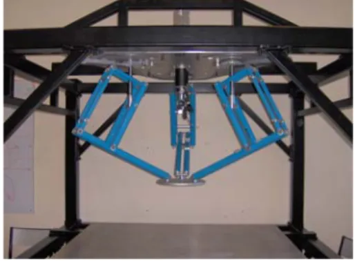
plane and the translation along the vertical axis. In other words, in the design of the PAMINSA, a partial decoupling of motions is achieved, which provides several mechanical advantages. Mechanical, kinematic and dynamic characteristics, as well as the mechanical properties of the invented manipulator, have been studied in our previous works [7-10] and a prototype of PAMINSA with 4-DOF (Fig. 1) was built in the I.N.S.A.
Fig. 1. The prototype of the PAMINSA with 4-DOF. We would like to renote in few words the obvious advantages of the suggested manipulator architecture: (i) the decoupling of the control powers in two parts, making possible to raise an important payload to a fixed altitude by powerful actuators and then to displace it on the horizontal plane by less powerful actuators; (ii) the cancellation of static loads on the rotating actuators which displace the platform in the horizontal plane; (iii) a great accuracy in the horizontal positioning because the payload can be locked in the horizontal plane by mechanical architecture of the manipulator; (iv) the use of the less powerful actuators for the generation of motions on the horizontal plane; (v) the simplification of the vertical control based on linear input/output relationships (note that the vertical
displacement of the platform is a copy of the linear displacement of the actuator multiplied by a magnification factor).
In this paper the singularity analysis of the different types of PAMINSA from 4 to 6 degrees of freedom is presented and kinematic interpretations of the singular configurations are provided. The organization of this paper is as following. The second section describes the kinematics of the PAMINSA manipulators with different degrees of freedom. The third section uses the obtained Jacobian matrices for the singularity analysis of the manipulators and kinematic interpretations of the singular configurations are given.
II. Kinematics of the PAMINSA manipulators
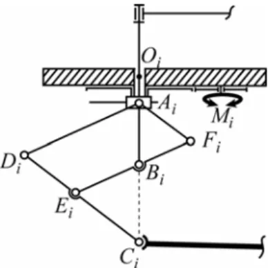
The family of the PAMINSA manipulators [10] is based on the copying properties of the pantograph linkage, which composes the kinematic chain between the fixed base of the manipulator and its end-effector (Fig. 2). Thus each leg of the suggested manipulator is a pantograph linkage with two input parameters. This makes it possible to decouple the displacements between the horizontal plane and the vertical axis.
Fig. 2. Schematics of one leg of PAMINSA manipulators
For each kind of PAMINSA, the input points are Ai and Bi and the output point is Ci. If the point Ai is
displaced horizontally, we obtain a horizontal displacement of the point Ci. If the point Bi is
displaced vertically, we obtain a vertical displacement of the point Ci. Displacements of point Ci are
amplified by the magnification factor of the pantograph.
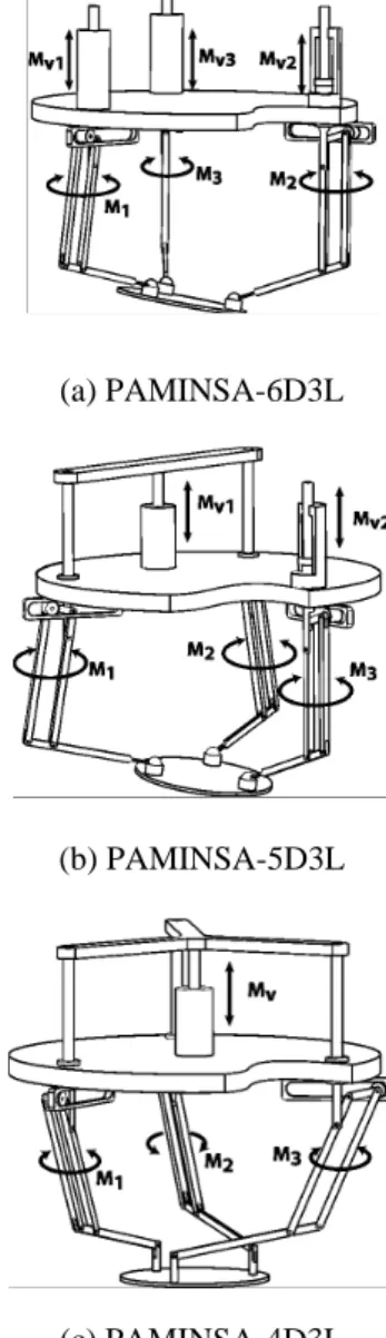
The PAMINSA-6D3L (Fig. 3a) is a manipulator with 6 degrees of freedom composed of 3 legs. The points Ai are actuated on the horizontal plane by 3
motors Mi which control directly the rotation of the
revolute joints Ri. The rotations of the three legs allow
the displacements of the platform on the horizontal plane (2 translations and one rotation about the vertical axis). The point Bi of each leg is controlled by an
independent actuator. The vertical translation is controlled by the simultaneous vertical displacements of points Bi of the 3 legs. The orientations about two
other axes is obtained by the vertical displacements of the point Bi of the legs.
For the PAMINSA-5D3L (5-DOF – Fig. 3b), the rotations of the three legs allow the displacements of the platform in the horizontal plane. Points Bi of two of
the three legs are linked to the same actuator and the third leg has an independent vertical actuation. The vertical translation and one inclination of the platform are obtained as previously.
(a) PAMINSA-6D3L
(b) PAMINSA-5D3L
(c) PAMINSA-4D3L
For the PAMINSA-4D3L (4-DOF – Fig. 3c), the rotations of the three legs allow the displacements of the platform in the horizontal plane. The vertical displacements of the point Bi are controlled by only
one actuator MV. Thus, the motors Mi control the
displacement of the platform on the horizontal plane and the motor MV controls the displacement towards
the vertical axis.
It should be noted that the PAMINSA with 5-DOF can be assimilated to a PAMINSA with 6-DOF whose first two linear actuators have the same displacements. Thus one inclination of the platform is prevented. In a similar way, the PAMINSA with 4-DOF is a PAMINSA with 6-DOF whose whole linear actuators have the same displacements. Whole inclinations of the platform are prevented and only one rotation about the vertical axis is allowed.
Thus, in the general case, the kinematics of the PAMINSA-6D3L describes the kinematics of the other manipulators. The position of the centre of the platform P and the orientation of the moving frame {M} in the base frame {B} (x-axis is collinear to O1O2 and z-axis is vertical) are represented by
x=(x,y,z,φ,ψ,θ)T and the actuated variables by
q=(β,,β2,β3,Z1,Z2,Z3)T. Parameters x, y, z, φ,
ψ , θ represent respectively the three components of the position of point P and the three rotation angles of the platform. The angles φ, ψ and θ can be obtained by expressing the directional cosines in terms of z-x-z Euler angles φ, ψ, θ. Parameters β1, β2, β3, Z1, Z2,Z3
represent respectively the rotations of the three legs of the manipulator about the z-axis of frame {B} and the vertical position of points Bi. Note that for the
following analyses, O1O2O3 and C1C2C3 represent
equilateral triangles.
The closed loop relations relative to x and q can be expressed as:
for (i=1,2,3) (1-6) where
- cα and sα represent the cosines and sinus of angle α respectively (α = βi, γ i, φ, ψ and θ)
- k is the magnification factor of the pantograph - Rn and Rb are the platform and base radii
respectively - xOi =Rbcosγi, yOi =Rbsinγi, T n i T T Ci Ci Ci i R z y x z y x C ] 0 , 0 , [ ) , ( ) , ( ) , ( ] , , [ ] , , [ z x z ψ θ γ φ + + = ≡ Rot Rot Rot and γi =(−5π/6,−π/6,π/2), (i=1,2,3)
with Rot(α,w) the matrix representing the rotation of angle α around the w-axis of the intermediate frame (w = x, y and z).
III. Singularity analysis
The singularity analysis has attracted the attention of several researchers and different studies have been published [11-20]. Zlatanov in [12] presented a method that can identify the singularities of both passive and active chains by studying the deficiency of the rank of an augmented non-square Jacobian matrix. However this analysis is quite difficult and not useful for the PAMINSA manipulators. The singularity analysis presented here is carried out by Gosselin and Angeles approach [11], based on the properties of the Jacobian kinematic matrices of the mechanical structure, i.e. when the Jacobian matrices relating the input velocities and the output velocities become rank deficient.
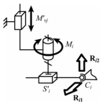
PAMINSA are parallel manipulators in which singular configurations can be separated into two cases: singularities of the pantograph linkage used as a leg and singularities of the simplified schematic representation of the PAMINSA manipulators in which the pantograph mechanism is replaced by a chain PRPS (Fig. 4). The pair S’i corresponds to the free
translational displacement of both prismatic pair Si and
pantograph linkage. The actuators M’vj correspond to
actuators Mvj whose displacement is amplified by the
magnification factor of the pantograph. In PAMINSA manipulators, these singularities are not coupled and can be examined separately.
It may be noted that the singular configurations of pantograph linkage can be found by an analysis of the articulated parallelogram. They are well known and we shall not deal with. The study below is only devoted to the singularities of the 3-PRPS parallel structure.
Fig. 4. Simplified schematic representation of the i-th actuated leg.
PAMINSA-6D3L: Differentiating equations (1-6) with respect to time, we obtain a 6 dimensional system:
0 Bt q A&+ = (7) (j=i) ⎩ ⎨ ⎧ = − = − − − = 0 0 ) ( ) ( Ci i i Oi Ci i Oi Ci j z Z k c y y s x x f β β (j=i+3)
where ⎥ ⎥ ⎥ ⎥ ⎥ ⎥ ⎥ ⎥ ⎦ ⎤ ⎢ ⎢ ⎢ ⎢ ⎢ ⎢ ⎢ ⎢ ⎣ ⎡ = ⎥ ⎦ ⎤ ⎢ ⎣ ⎡ ∂ ∂ = k sym k k q f i j 0 0 0 0 0 0 0 0 0 0 0 0 0 0 0 3 2 1 ρ ρ ρ A ⎥ ⎥ ⎥ ⎥ ⎥ ⎥ ⎥ ⎥ ⎦ ⎤ ⎢ ⎢ ⎢ ⎢ ⎢ ⎢ ⎢ ⎢ ⎣ ⎡ − − − − − − = ⎥ ⎦ ⎤ ⎢ ⎣ ⎡ ∂ ∂ = 66 56 65 55 64 54 63 53 43 3 3 62 52 42 2 2 61 51 41 1 1 0 1 0 0 0 1 0 0 0 1 0 0 0 0 0 d d d d d d d d d c s d d d c s d d d c s x f i j β β β β β β B T z y x, , , , , ]
[& & &φ&ψ& θ& = t T Z Z Z , , ] , , ,
[&1 &2 &3 &1 &2 &3 &= β β β q 2 2 ) ( ) ( Ci Oi Ci Oi i= x −x + y −y ρ (i=1,2,3) ) ( ( ) ( ) ( ) ( ) 4i Rn c ic i c s is i d = θ+γ φ+β + ψ θ+γ φ+β (i=1,2,3)
Singularity of parallel manipulators appears when matrices A and B are rank-deficient. We will deal only with the singularities of the first and the second type. Third type singularities are a mix a both Type 1 and 2 singular configurations.
Examining matrix A and B of PAMINSA with 6-DOF, it appears that:
3 2 1 3 ) det(A =k ρ ρ ρ (8) ) 8 /( 27 ) det(B = Rn3cψsψ ∆ ρ1ρ2ρ3 (9) where ∆ is the expression of a conic given in appendix
A.
First of all, it should be noted that the expressions of det(A) and det(B) do not depend of the altitude z of the platform.
det(A) = 0 involves that the manipulator is in Type 1 singularity. This expression is achieved when ρi is
equal to 0 (i=1,2,3), i.e. points Oi, Bi and Ci are
aligned. In such configuration, one rotation of the input link Mi cannot bring to the displacement of the
platform (Fig. 5).
The study of det(B) is much more complicated. This expression is the product of many terms which have to be conscientiously analyzed.
Fig. 5. Example of first type singularity. Thus, det(B) = 0 if:
(a) the inclination angle ψ is equal to 0 (or π); such case is physically meaningless. This is a formulation singularity due to the use of the Euler-angles formulation [21]. If ψ = 0 (or π), rotations of angles φ and θ are equivalent (about the same z-axis).
Thus Type 2 singularities only correspond to cases (b), (c) and (d) and appear when:
0 ) 8 /( 27 3 ∆ 1 2 3 = = R cψ ρ ρ ρ D n (10)
(b) the inclination angle ψ is equal to ±π/2; in such configuration, the rotation about the axis x of angle ψ is impossible and small rotations of the platform are allowed (Fig. 6a).
(c) for any fixed altitude, the platform is on a conic ∆ = 0 located in the horizontal plane. The coefficients of ∆ depend on the orientation angles of the platform. Thus, for given values of angles φ, ψ and θ, this singularity is only due to a particular configuration of actuators M1, M2 and M3. It
appears when the three wrenches Ri1 [22] (applied
on the platform by the actuators Mi and located on
the horizontal plane– see Fig. 4) intersect a unique line W perpendicular to the horizontal plane (Fig. 6b). In such case, this line is the instantaneous axis of rotation of the moving plate;
(d) the length ρ1, ρ2 or ρ3 tend to+∞ , what means that
the legs of the manipulator are parallel. Thus the platform is able to translate along the direction of the passive prismatic pairs S’i (Fig. 6c).
PAMINSA-5D3L: As previously noted, the PAMINSA with 5-DOF can be assimilated to a PAMINSA with 6-DOF whose first two linear actuators have the same displacements. Thus angle θ is equal to 0. To find its singularity loci, these constraints have to be introduced in the expressions of det(A) and D. (i=1,2,3) ⎩ ⎨ ⎧ − = + + + ) ( ) ( ) ( 5 i n i i n i R c s s c s R d γ θ ψ γ θ β φ ψ (i=4,5,6) (i=1,2,3) ⎩ ⎨ ⎧ − + − = + + + + + ) ( ) ( ) ( ) ( ) ( 6 ) ( i n i i i i n i c s R c c c s s R d γ θ ψ β φ γ θ ψ β φ γ θ (i=4,5,6)
(a) singularity of case (b), planar front view of the manipulator
(b) singularity of case (c), top view of the 3-PRPS manipulator
(c) singularity of case (d), top view of the 3-PRPS manipulator Fig. 6. Examples of second type singularities As for the previous case, the manipulator is in Type 1 singularity when ρi is equal to 0 (i=1,2,3), i.e.
points Oi, Bi and Ci are aligned. Furthermore, the
manipulator is in Type 2 singularity when:
(a) the inclination angle ψ is equal to ±π/2. This case correspond to figure 6a;
(b) for any fixed altitude, the platform is on a conic Λ = 0 located in the horizontal plane. The coefficients of Λ depend on the orientation angles φ and ψ of the platform. Their expressions are given at appendix B. This case corresponds to figure 6b;
(c) the length ρ1, ρ2 or ρ3 tend to∞. This case
correspond to figure 6c.
The kinematic interpretation of these singularities is the same as for the previous manipulator.
PAMINSA-4D3L: Similarly to the previous case, the PAMINSA with 4-DOF can be assimilated to a PAMINSA with 6-DOF whose linear actuators have the same displacements. Thus angles ψ and θ are equal to 0. These new constraints have to be introduced in the expressions of det(A) and D.
The Type 1 singularities are not different from the previous manipulators. The Type 2 singularities appear when:
(a) the angle φ is equal to ±arccos(Rn/Rb);
(b) for any fixed altitude, the platform is situated on a circle located in the horizontal plane, whose radius depends on angle φ. The expression of this circle is: φ cos 2 2 2 2 2 b n n b R R R R y x + = + − (11)
(c) the length ρ1, ρ2 or ρ3 tend to+∞ .
Cases (a) and (b) correspond to figure 6b and case (c) to figure 6c.
Finally, we would like to note that, in the present work, the singularity analysis was carried out only by taking into account the kinematic relationships. In practice, this problem is much more complicated and it may be studied with kinetostatic and dynamic aspects. Among several effects, which can modify the singularity analysis conditions, we would like to note the friction. The singularity analysis of parallel manipulators, taking into account the friction in the joints, has been developed in our previous work [23].
IV. Conclusions
In this paper the singularity analysis of PAMINSA with four, five and six degrees of freedom has been presented. The singularities have been determined in analytic form by algebraic approach based on the analysis of the properties of the Jacobian matrices. The nature of each kind of singularity has been discussed and kinematically analyzed. In practice, the obtained results can be very useful in the selection of the optimal architectures of PAMINSA and in the problems of its optimal control.
References
[1] X. Kong and C. M. Gosselin, A class of 3-dof translational parallel manipulator with linear input/output equations, Workshop on Fundamental Issues and Future Research for Parallel Mechanisms and Manipulators, Québec City, Québec, Canada (2002) pp. 25–32.
[2] C. M. Gosselin, X. Kong, S. Foucault and I. Bonev, A fully decoupled 3-dof translational parallel mechanism, Parallel Kinematic Machines International Conference, Chemnitz, Germany (2004) pp. 595–610.
[3] M. Carricato and V. Parenti-Castelli, A novel fully decoupled 2-dof parallel wrist”, The International Journal of Robotics Research, 23(6) (2004) pp. 661–667.
[4] M. Carricato and V. Parenti-Castelli, On the topological and geometrical synthesis and classification of translational parallel mechanisms, Proc. of the 11th World Congress in Mechanism and Machine Science, Tianjin, China (2004) pp. 1624–1628. [5] B. C. Bouzgarrou, J. C. Fauroux, G. Gogu, and Y. Heerah,
Rigidity analysis of T3R1 parallel robot with uncoupled kinematics, International Symposium on Robotics, Paris, France (2004)
[6] V. Arakelian, P. Maurine, S. Briot, E. Pion. Parallel robot comprising means for setting in motion a mobile element split in two separate subassemblies. Patent FR2873317, 27 January 2006.
[7] V. Arakelian, S. Briot, A New Decoupled Parallel Manipulator with Four Degrees of Freedom. The 20th Canadian Congress of Applied Mechanics: CANCAM 2005, McGill University, May 30th to June 2nd, Montreal (2005) pp. 415-416
[8] S. Briot, P. Maurine, S. Guégan, V. Arakelian. Le PAMINSA : un nouveau manipulateur d’architecture parallèle aux mouvements découplés. Actes du 17-ème Congrès Français de Mécanique, du 29 août du 3 septembre, Troyes (2005). [9] V. Arakelian, S. Guegan, S. Briot. Static and dynamic analysis
of the PAMINSA. Proceedings of ASME 2005 IDETC/CIE Conference, September 24-28, Long Beach, California, U.S.A. (2005).
[10] V. Arakelian, S. Briot, S. Guegan, J. Le Flecher. Design and prototyping of new 4-, 5- and 6-DOF parallel manipulators based on the copying properties of the pantograph linkage. Proceedings of 36th International Symposium on Robotics ISR
2005, November 29 – December 1, Tokyo, Japan (2005). [11] C.M. Gosselin, J. Angeles. Singularity analysis of closed-loop
kinematic chains. IEEE Transactions on Robotics and Automatics. 6(3) (1990) pp.281-290.
[12] D. Zlatanov, R.G. Fenton and B. Benhabib. Singularity analysis of mechanisms and robots via a velocity-equation model of the instantaneous kinematics. Proceedings of the 1994 IEEE International Conference on Robotics and Automation, 2 (1994) pp. 980-991.
[13] J.-P. Merlet. Singular configurations of parallel manipulators and Grassmann geometry. The international Journal of Robotics Research. 8(5) (1989) pp. 45-56.
[14] B.M. St-Onge, C.M. Gosselin. Singularity analysis and representation of the general Gough-Stewart platform. The International Journal of Robotics Research. 19(3) (2000) pp.271-288.
[15] F. Pernkopf, M. Husty. Singularity analysis of spatial Stewart-Gough platforms with planar base and platform. Proceedings of the DECT 2002, Montreal (2002).
[16] J.T. Wen, J.F. Oapos Brien. Singularities in three-legged platform-type parallel mechanisms. IEEE Transactions on Robotics and Automation. 19(4) (2003) pp.720- 726.
[17] A. Wolf, E. Ottaviano, M. Shoham and M. Ceccarelli. Application of line geometry and linear complex approximation to singularity analysis of the 3-DOF CaPaMan parallel manipulator. Mechanism and Machine Theory, 39 (1) (2004) pp.75-95.
[18] S. Bandyopadhyay, A. Ghosal. Analysis of configuration space singularities of closed-loop mechanisms and parallel manipulators. Mechanism and Machine Theory, 39 (5) (2004) pp.519-544.
[19] J.-S. Zhao, Z.-J. Feng, K. Zhou and J.-X. Dong. Analysis of the singularity of spatial parallel manipulator with terminal constraints. Mechanism and Machine Theory, 40(3) (2005) pp.275-284.
[20] V.A.Glazunov, A.Sh. Koliskor, A.F. Krainev, and B.I. Model. Classification principles and analysis methods for parallel-structure spatial mechanisms, Journal of Machinery Manufacture and Reliability, Allerton Press Inc., 1 (1990) pp. 30-37.
[21] O. Ma and J. Angeles. Architecture Singularities of Parallel Manipulators. International Journal of Robotics and Automation, 7(1) (1992), pp. 23-29.
[22] F. M. Dimentberg. The screw calculus and its applications in mechanics. Technical report, Foreign Technology Division, Wright-Paterson Air Force Base, 1965.
[23] V. Arakelian, S. Briot, V. Glazunov. Increase of singularity-free zones in the workspace of parallel manipulators using mechanisms of variable structure (in press).
Appendix A 6 6 6 6 2 6 2 6x B y C xy D x E y F A + + + + + = ∆ ψ φ θ θ ψ φc s c c R c s R A6=2 b( + )−2 n ψ φ θ θ ψ φc c s s R c c R B6=2 b( + )−2 n ) ( 6 =2R (cψ −1)sθ+φ C b ) )) 2 ( 2 ) 2 1 ( )) 1 2 ( ) 1 ( 2 ( ( )) 3 4 ( ) ) 3 4 ( ) 4 1 )( 1 ( ( ( ( ) 1 ( ) ( 2 2 2 2 2 2 2 2 2 6 θ φ φ θ θ φ φ φ θ φ φ φ φ θ θ ψ θ θ φ θ φ θ θ ψ θ φ ψ ψ + − − + − + − + + − − + − + − + − − = s R c c s c s c c s s c c c s c R R c c s c s c c c s c c R c D b b n n ) ) 1 2 ) 1 ( 2 ) 2 ) 4 2 2 ( ( ( )) 4 3 ( )) 4 3 ( ) 4 1 )( 1 ( ( ( ( ) 1 ( ) ( 2 2 2 2 2 2 2 2 2 2 6 θ φ φ φ θ θ φ φ θ φ θ φ θ φ φ θ θ ψ θ θ φ θ θ φ θ ψ θ φ ψ ψ + + + + + + − + − − + − − + − + + − + + − + − − = c R s c s c c c c c c c c s c s c c R R c c c c c c c c s s c R c E b b n n 8 / ) 4 16 11 11 4 ( 8 / ) 4 18 6 6 4 8 ( 2 / ) 2 ( 4 / ) 7 ( ) 3 ( ) 2 ( ) ( ) 3 ( ) ( ) ( ) 2 2 ( 2 ) 2 2 2 ( ) 2 2 2 ( ) 2 2 ( ) ( 2 2 ) 2 2 ( 2 ) ( ) ( ) ( 3 3 3 6 φ θ ψ θ ψ φ φ θ φ θ ψ φ θ ψ φ θ ψ θ ψ φ θ ψ φ θ ψ φ θ ψ φ θ φ ψ φ θ ψ ψ θ φ θ ψ φ θ ψ φ ψ ψ + − − − + − + − − + − + − − − + − + − − − + − + − − − − − − + + + + + + + − + + + + + + + + + − + = c c c c c c c R R c c c c c c c R R c c c R c c R F b n b n b n Appendix B 5 5 5 5 2 5 2 5 ) 0 ( = =A x +B y +C xy+D x+E y+F ∆ = Λ θ ψ φ R c c R A5=2 b −2 n ) ( 2 5 c Rbc Rn B = ψ φ− φ ψ s c R C5=2 b( −1) ) ) 1 ( ) 1 ( ( ) 1 ( 2 2 5 cψ R sφ cψ R Rcφ cψ R sφ D = − − n + − n b − + b ) ) 2 1 ) 1 ( ( )) 1 ( ( ( ) 1 ( 2 2 2 5 φ ψ ψ φ ψ φ ψ c R c c c R R c c R c E b b n n + − − − + + − − = )) 1 )( 1 ( ) ) 1 ( ) 1 ( ) 1 ( ( ) 1 ( ) 1 ( 2 2 2 2 2 2 3 3 2 5 ψ ψ ψ φ ψ φ ψ ψ φ ψ φ ψ ψ c c c c R R c c c c c R R c c R c R c F b n b n b n − − − + − + + + + + + − + =