Science Arts & Métiers (SAM)
is an open access repository that collects the work of Arts et Métiers Institute of Technology researchers and makes it freely available over the web where possible.
This is an author-deposited version published in: https://sam.ensam.eu
Handle ID: .http://hdl.handle.net/10985/8756
To cite this version :
Sandra ZIMMER-CHEVRET, Laurent LANGLOIS, Julien LAYE, Jean-Claude GOUSSAIN, Patrick MARTIN, Régis BIGOT - Using the plunging and welding process windows to determine a FSW means of production - Advanced Materials Research - Vol. 89-91, p.697-702 - 2010
Any correspondence concerning this service should be sent to the repository Administrator : archiveouverte@ensam.eu
Using the plunging and welding process windows to determine a FSW
means of production
Sandra ZIMMER
1, a, Laurent LANGLOIS
1,b, Julien LAYE
2,c, Jean-Claude
GOUSSAIN
2,d, Patrick MARTIN
1, e, Régis BIGOT
1, f1
Arts et Métiers ParisTech, LCFC, 4, Rue Augustin Fresnel, 57070 Metz, France
2
Institut de Soudure - FSW Center, 2-4 rue Pilâtre de Rozier, 57420 Goin, France
a
sandra.zimmer@metz.ensam.fr, blaurent.langlois@metz.ensam.fr, cj.laye@institutdesoudure.com,
d
jc.goussain@institutdesoudure.com, epatrick.martin@metz.ensam.fr, frégis.bigot@metz.ensam.fr Keywords: Friction Stir Welding, Industrialization, Plunging stage, process windows
Abstract: This paper presents an experimental methodology to determine a Friction Stir Welding
(FSW) means of production based on the experimental study of the tool / material mechanical interactions generated during the plunging and welding stages. These two stages have been identified as being characteristic for the qualification of a FSW equipment. This paper presents the experimental results of the parametric study done on the plunging and welding phases. Ranges of forces and torques diagrams were established according to the processing parameters, in order to qualify a means of production and select the process parameters allowing the operation on the available FSW equipment.
Introduction
Friction Stir Welding (FSW) is an innovative welding process commonly known as being a solid state welding process [1]. Its particularity is to join material without reaching the fusion temperature, giving it the availability to weld almost all types of aluminum alloys, even the one classified as non-weldable by fusion welding due to hot cracking and poor solidification microstructure in the fusion zone, like the 2000 or the 7000 aluminum alloy [2]. To perform FSW, a non-consumable rotating tool, composed by a shoulder and a pin, is inserted into the interface of two rigidly clamped workpieces to avoid any movement. Once the shoulder in contact with the workpieces surface, it is moved along the joint line, bounding the workpieces together by heating and stirring the workpieces material. The welding processing parameters, axial force Fz, travel
speed va and spindle rotational frequency N, are ensuring the required heat energy input to create
the join. The process generates non-negligible process forces and torques which are transmitted to the welding equipment, impacting its characteristics.
Today, most applications are in the transportation industries. With its characteristics, Friction Stir Welding should be more widespread in the industry. The lacks of industry standards, design guidelines and informed axial force or the high cost of capital equipment are, according to Arbegast [3], barriers to the FSW expansion. Our research work is the industrialisation of the FSW, in order to provide tools to industrials to qualify a welding equipment and define its technical requirements. Therefore, a methodology based on the analysis of the kinematical and mechanical interactions generated during welding between the product, the process and the resources was developed by Zimmer and al. [4]. The idea is to analyze the interactions generated during welding between the tool / workpiece and the tool / material. The analysis of the tool / workpiece interactions, a global approach, leads to the determination of the position and orientation of the tool during welding, according to the welding surface and to the definition of the tool trajectory. So, it defines the
equipment workspace required and the tool accessibility. In the other way, the study of tool /
according to the welding surface. It also defines the tool kinematics and the mechanical load
applied on the tool. It leads to the determination of the characteristics parameters in order to write
down the technical requirements for the equipment. This paper will concentrate on the experimental
analysis of the tool / material mechanical interactions occurring during FSW and of the influence
of the processing parameters on them.
Global analysis of the mechanical interaction generated during FSW
The tool / material mechanical interactions have been analyzed through the process forces and torque generated. To proceed, the welding process has been decomposed into 6 independent phases. The Fig. 1 presents the phase’s decompositions and the mechanical interaction applied on the tool during FSW. The study, performed on several aluminium alloy and thicknesses, shows that the plunge and welding at constant speed stage are characteristic for a static qualification of the welding equipment [4]. During the plunge stage, the axial force Fz and spindle torque Cz know a maximum
at the end of plunge. These short peaks were identified as being characteristic for a static qualification of the welding equipment [4]. In the same manner the spindle torque, the axial forces, Fz, and the forces Fx and Fy which can be greater than 10% of Fz according to the processing
parameters, are characteristic for a static qualification of the welding equipment [4]. Therefore, in order to enable the use of standard equipment allowing the FSW of complex geometries a parametric study has been realized on these two characteristic phases to see if the load transmitted to the welding equipment can be reduced. All the trials were performed on an instrumented MTS-ISTIR-10 Friction Stir Welder at the Institut de Soudure on a 6mm thick, 6000 aluminium alloy series. For all trials, the plunging stage was displacement controlled and the welding stage was force controlled. -2 -1 0 1 2 3 4 5 6 7 8 9 10 11 12 13 14 25.5 27.5 29.5 31.5 33.5 35.5 37.5 39.5 41.5 43.5 45.5 47.5 49.5 51.5 53.5 55.5 57.5 Temps [sec] F o rc e s [ k N ] 0 5 10 15 20 25 30 35 40 45 50 55 60 65 70 T o rq u e [ N m ]
Travel Force Lateral Force Axial force Spindle Torque
Time [s] -2 -1 0 1 2 3 4 5 6 7 8 9 10 11 12 13 14 25.5 27.5 29.5 31.5 33.5 35.5 37.5 39.5 41.5 43.5 45.5 47.5 49.5 51.5 53.5 55.5 57.5 Temps [sec] F o rc e s [ k N ] 0 5 10 15 20 25 30 35 40 45 50 55 60 65 70 T o rq u e [ N m ]
Travel Force Lateral Force Axial force Spindle Torque
Time [s]
Axial Force, Fz
Force perpendicular to the travel direction, Fy
Force in the travel direction, Fx
Weld speed Schematization
Plunge
Dwell Time Acceleration
Welding at constant speed Deceleration
Retracting of the tool
Spindel Torque
Fig. 1: Forces and spindle torque applied on the tool during the friction stir operation of 6000 aluminum alloy Plunge and welding stages experimental investigation
The Fig. 2 presents the input and output parameters of the two studied stages with an emphasis on the load transmitted to the FSW welding equipment. Special attention will be paid to the influence of the FSW processing parameters on these parameters. Firstly, the main results will be presented for the plunging stage, then for the welding at constant speed stage.
Process
Processing Parameters Output Parameters
Power [W]
FSW
Welding at constant rotational and travel
speeds Fx[kN] Nominal Energy [J/mm] Cz[Nm] Weld quality Fz[kN] vtravel [mm/min] N [tr/min] i[°] Fy[kN] Power [W]
FSW
Welding at constant rotational and travelspeeds Fx[kN] Nominal Energy [J/mm] Cz[Nm] Weld quality Fz[kN] vtravel [mm/min] N [tr/min] i[°] Fy[kN]
Parameters transmitted to the FSW welding machine Processing Parameters Process Output Parameters
FSW
Plunging stage ap[mm/min²] vp[mm/min] Np[tr/min] dp[mm/min²] i[°] Fx[kN] Cz max[Nm] Power [W] Fz max [kN] Fy[kN]FSW
Plunging stage ap[mm/min²] ap[mm/min²] vp[mm/min] vp[mm/min] Np[tr/min] Np[tr/min] dp[mm/min²] dp[mm/min²] i[°] i[°] Fx[kN] Fx[kN] Cz max[Nm] Cz max[Nm] Power [W] Power [W] Fz max [kN] Fz max [kN] Fy[kN] Fy[kN]A
B
Fig. 2: Relationship between the studied output and input parameters, A for the plunge stage, B for the welding at constant speed stage.
Analysis of the plunge stage Experimental procedure
Plunge experimental testing were performed in order to study the influence of the principal processing parameters, Fig. 2, the rotational speed Np and the plunging speed vp,, on the maximal
axial force and torque, Fz max and Cz max. To proceed a variation of 33% and a 66% was applied on
Np and vp according to the plunge processing parameters used during the welding operation. The
tool acceleration / deceleration were calibrated in the same manner for each trial.
Evolution of the output parameters when Np and vp are evolving
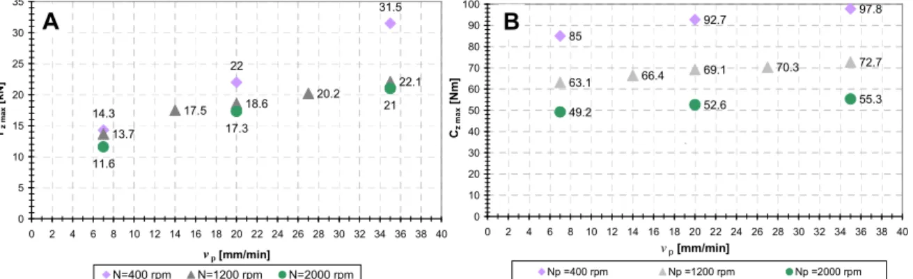
The Fig. 3 presents the evolution of Fz max and Cz max according to Np for vp set up at different
values, respectively 7, 14, 20, 27 and 35 mm/min. Two general tendencies can be identified. The first one is for a given Np, the values of Fz max and Cz max increases as vp increases. The second
tendency is for a given vp, as Np increases, the maximal forces and torques decreases. This is due to
the change of the generated thermo-mechanical interactions between the tool and the workpiece. The global analysis shows that Fz max is a function of Np and vp but is more sensitive to the
evolutions of vp than Np. On the other side, Cz max is still a function Np and vp but is more sensitive to
the evolutions of Np than vp. So, the lowest axial force and spindle torque occurred when the spindle
frequency is the highest and the plunging speed is the lowest, i.e. when the heat input generated due to friction between the tool and the workpiece is the highest and the generated heat has time to be dissipated inside the workpiece by conduction, increasing the workpiece temperature in the plunging zone. 14.3 22 31.5 13.7 17.5 18.6 20.2 22.1 11.6 17.3 21 0 5 10 15 20 25 30 35 0 2 4 6 8 10 12 14 16 18 20 22 24 26 28 30 32 34 36 38 40 v p [mm/min] Fz m a x [ k N ] N=400 rpm N=1200 rpm N=2000 rpm 85 92.7 97.8 63.1 66.4 69.1 70.3 72.7 49.2 52.6 55.3 0 10 20 30 40 50 60 70 80 90 100 0 2 4 6 8 10 12 14 16 18 20 22 24 26 28 30 32 34 36 38 40 vp [mm/min] Cz m a x [ N m ] Np =400 rpm Np =1200 rpm Np =2000 rpm . B A
Fig. 3: A - Fz max evolution according to Np for vp set up as constant. B- Cz max evolution according to Np for vp set
up as constant.
Process repeatability
The Fig. 4 presents the evolution of the axial force and the spindle torque measured for three plunge trial performed at identical processing parameters. Their evolution over the plunging depth are the same, their maximal values are in the same order of magnitude and are occurring at the same location. Therefore it can be concluded that the thermo-mechanical conditions are identical and repeatable over successive trial performed at identical processing parameters. However, the experiments showed some variability of the maximal axial force value for trials performed at
identical processing parameters. Peak amplitude difference can reach 20%, therefore. This variability has to be taken into account.
0 1 2 3 4 5 6 7 8 9 10 11 12 13 14 15 0 0.5 1 1.5 2 2.5 3 3.5 4 4.5 5 5.5 Plunging depth [mm] Fz [ k N ]
Trial 1 Trial 3 Trial 2
Trial 1: Fz max = 12.7 kN Trial 2: Fz max = 13.5 kN Trial 3: Fz max = 14.7 kN Processing parameters: Np = 1200 rpm, vp = 7 mm/min 30 35 40 45 50 55 60 65 0 0.5 1 1.5 2 2.5 3 3.5 4 4.5 5 5.5 Plunging depth [mm] Cz [ N m ]
Trial 1 Trial 2 Trial 3
Processing parameters: Np = 1200 rpm, vp = 7 mm/min Trial 1: Cz max = 63.3 Nm Trial 2: Cz max = 62.5 Nm Trial 3: Cz max = 63.3 Nm B A
Fig. 4: Force and torque evolution of three trials done at the same processing parameters. A, axial force
evolution Fz. B, spindle torque evolution Cz.
Force and torque diagram according to the processing parameters
By combining the Fz max and Cz max recorded inside one diagram, according to the processing
parameters, one obtains what could be named a “plunging test experimental diagram”, presented on Fig. 5. Forces and torques ranges can be observed. This kind of diagram is interesting for choosing the processing parameters according to the available means of production, i.e. according to the range of force and torque generated. It can also be used to select the best compromise between the developed forces and torque and the stage productivity related to the plunge velocity.
0 200 400 600 800 1000 1200 1400 1600 1800 2000 0 2 4 6 8 10 12 14 16 18 20 22 24 26 28 30 32 34 36 38 40 42 44 46 48 Plunging speed, vp [mm/min]
R o ta ti o n a l F re q u e n c y , Np [ rp m ] (11.6kN ; 49.2Nm) (16.5kN ; 57.9Nm) (13.7kN ; 63.1Nm) (17.5kN ; 66.4Nm) (16.8kN ; 77.2Nm) (14.3kN ; 85Nm) (Fz max ; Cz max) (19kN ; 60Nm) (20.2kN ; 60.5Nm) (17.3kN ; 52.6Nm) (21kN ; 55.3Nm) (23.7kN; 55.5Nm) (18.6kN ; 69.1Nm) (22.1kN ; 72.7Nm) (23.2kN; 72.3Nm) (20.2kN ; 70.3Nm) (18kN ; 80.5Nm) (19kN ; 82.2Nm) (22kN ; 92.7Nm) (31.5kN ; 97.8Nm) (35kN ; 100Nm) 25kN 40kN 20kN 15kN 10kN
Axial force gray level force range
Fig. 5: Maximal axial force and spindle torque according to Np and vp
To qualify a FSW welding equipment, it is important to consider the plunging but also the welding at constant speed stage. Therefore, an experimental study has also been made on this stage. It would be interesting, from an industrialization point of view, to draw a diagram equivalent of the Fig. 5 for the welding stage.
Analysis of the welding at constant speed stage
The analysis of the welding at constant stage was performed through the determination of the studied alloy process windows. The criterion for its definition was the realization of a sound weld, i.e. without any internal or external defect. The varying parameters are the three principal welding processing parameters, the tool rotational speed, N, the travel speed, va and the axial force Fz. The
Experimental procedure
On the welding stage, the most characteristic parameter for a static qualification of a welding equipment is a process input parameter, Fz, Fig. 2. So, this parameter is controlled but its setting is
related to material thermo-mechanical conditions leading from the tool / workpiece mechanical interactions resulting from the application of N, va and Fz. So, the applied force is depending on the
material and thickness to be welded, the tool geometry, N and va. The determination of the process
window of the studied material showed that it was possible to applied different ranges of forces for a given N and va.
Evolution of the travel force, Fx, and Cz when N and Fz is evolving
On the Fig. 6-– A, the spindle torque mean value evolution can be observed, for a given va,
according to Fz and N. The spindle torque is reduced when the spindle frequency is increased.
Higher spindle frequency implies higher material strain rate around the tool but also a frictional heat input increase leading to a material temperature increase. The temperature increase and the high material strain rate, due to the stirring, are reducing the material consistency and consequently its viscosity involving the rotational drag reduction. The analysis showed that the spindle torque doesn’t seem to be sensitive to the travel speed increase and it can be concluded that the material flow around the tool, related to the tool travel motion, isn’t significant in the material heat input. However, the travel force Fx is very sensitive to variation of va, Fig. 6-B. Fx is decreasing with a
decrease of va and consequently an heat input decrease, at N constant. This travel force decrease
could be explained by an increase of the plasticised zone in front of the pin, due to more heat input, facilitating the tool travel along the workpiece interface [5]. The results showed that Fx maximal
values could reach 38% of the parameterized value Fz. Therefore, Fx has to be taken into account for
a static qualification of a FSW equipment.
85 93 97 66 69 72 40 50 60 70 80 90 100 40 50 60 70 80 90 100 Fz / Fz max [%] C z / C z m a x [ % ] N=1200 rpm N=1300 rpm N=1800 rpm N=800 rpm A B 7.2 15.8 37.9 5.8 3.6 7.2 9.3 10 11.5 7.9 0 5 10 15 20 25 30 35 40 0.8 1 1.2 1.4 1.6 1.8 2 2.2 2.4 2.6 2.8 3 3.2 3.4 3.6 3.8 4 4.2 R = N / Va [tr/mm] F x / F z [ % ] Fx=f(Va); N=cst Fx=f(N); Va=cst En = 409 J/mm E n = 1541 J/mm
Fig. 6: A- Presentation of the spindle torque evolution according to N and Fz. B- Travel force, Fx, evolution
according to R for N and va constant.
The forces and toque analysis showed that the Cz, Fx and Fy can be influenced by the processing
parameters. It also showed that for a given N and va, for our material, thickness and tool a range of
different process force can be applied.
Force range diagram according to the processing parameters
By plotting the process force according to N and va leading to a sound weld into a diagram, ranges
of forces can be distinguished, Fig. 7. The same diagram can be drawn for the spindle torque. This
representation permit to select the welding processing parameter combination (Fz, N, va) according
to the available FSW equipment or to the required process productivity. More generally, the study showed that it was possible to reduce the process forces by working on the processing parameters in order to allow the welding with a standard and flexible mean of production, like a robot to reduce
Process Window Force range, according to N and va
v a [mm/min] v a min va max N min Nmax N [tr/min] 16kN 20kN 14kN 12kN 10kN 16kN 20kN 14kN 12kN 10kN Axial force gray level force range
Fig. 7: Welding process windows and force ranges
The established diagrams, Fig. 5 and Fig. 7, are interesting tools for the process industrialization, because they entirely define the FSW operation. Furthermore, they permit to select the processing parameters according to the generated forces and torque according to available welding equipment characteristics. They should be defined for different material, thicknesses and tool geometries in order to form a process parameters welding data base like it is available in machining. The establishment of these kind diagrams is probably the key to the FSW expansion but one step should be done before, the standardization of the tool geometries.
Conclusion and future work
To qualify a FSW equipment experimental investigations have been performed on the welding at constant speed stage and the plunging stage. It permits to evaluate the tool / material interactions through the process forces and torque generation according to the processing parameters, for one material, thickness and tool geometry. The experimental results permit to establish diagrams presenting the axial force according to the processing for the two stages characteristics for a FSW equipment static qualification. These diagrams permit to select the process windows ranges allowing the FSW with the available mean of production. To complete these work, another dimension should be added to this diagram, the weld mechanical properties in order to select the processing according to the weld quality and the available FSW equipment.
Acknowledgement
The authors would like to thanks the Region Lorraine and the Moselle department to financially support this research project and Daniel Strina for its technical support.
References
[1] W.M. Thomas, E.D. Nicholas, J.C. Needham, M.G. Murch, P. Templemith, C.J. Dawes (1991). Patent Application No. 9125978.8
[2] R.S Mishra, Z.Y. Ma, Friction Stir Welding and processing, Materials Sciences and Engineering R 50 (2005) I-78
[3] W. J. Arbegast, Application of Friction Stir Welding and related technologies. Friction Stir Welding and Processing ISBN: 978-0-87170-840-3, Chapter 13 p.274
[4] S. Zimmer, L. Langlois, J. Laye, J.-C. Goussain, P. Martin, R. Bigot, Methodology for qualifying a Friction Stir Welding equipment, Proceedings of the 7th International Symposium on Friction Stir Welding 2008
[5] S. Sheiki, Herstellung und Bewertung der Umformbarkeit von reibrührgeschweissten Tailored blanks aus Aluminiumlegierungen, Ph. D Work, University of Duisburg-Essen – 2005