Science Arts & Métiers (SAM)
is an open access repository that collects the work of Arts et Métiers Institute of Technology researchers and makes it freely available over the web where possible.
This is an author-deposited version published in: https://sam.ensam.eu Handle ID: .http://hdl.handle.net/10985/6741
To cite this version :
Li LU, Bassel ASLAN, Luc KOBYLANSKI, Paul SANDULESCU, Fabien MEINGUET, Xavier KESTELYN, Eric SEMAIL - Computation of Optimal Current References for Flux-weakening of Multi-Phase Synchronous Machines - In: IECON 2012 (38th Annual Conference of the IEEE Industrial Electronics Society), Canada, 2012-10-25 - IECON 2012 - 2012
Any correspondence concerning this service should be sent to the repository Administrator : archiveouverte@ensam.eu
Computation of Optimal Current References for
Flux-weakening of Multi-Phase Synchronous
Machines
Li Lu (1), Bassel Aslan (1), Luc Kobylanski(2), Paul Sandulescu(1), F.Meinguet(1), Xavier Kestelyn(1) and Eric Semail(1)
(1) Arts et Metiers Paristech – L2EP, 8 Bd Louis XIV, 59046 Lille France (2) VALEO-EEM, 2 rue André Boulle, 94000 Créteil France
Corresponding author : Xavier.Kestelyn@ensam.eu
Abstract -Multi-phase synchronous machines are more and more
used in specific applications where high power density, low bus voltage, wide speed range and fault-tolerant capabilities are required. Due to the high number of degrees of freedom, multi-phase machines are difficult to optimally operate in flux-weakening zones. This paper proposes a technique to numerically compute optimal current references that can be used for feed-forward flux-weakening techniques in order to exploit the maximum machine performances for given DC bus voltage and current limits. The proposed technique is applied to a five-phase permanent magnet synchronous machine specifically developed for an automotive application.
I. INTRODUCTION
Multi-phase synchronous machines are more and more used in specific applications where high power density, low DC bus voltage, wide speed range and fault-tolerant capabilities are required [1]. The automotive context offers a perfect example where multi-phase permanent magnet machines are now used. Low voltage DC bus, around 60V, insures an easy electrical security and reduces constraints on the Battery Management Systems (BMS). In the range from 10 to 20 kW, three-phase machines are not well suited because the resulting phase currents would be too large. Consequently, multi-phase machines become a good solution to reduce phase currents since it is possible to split the power into more than three phases. In MHYGALE project, proposed by Valeo and funded by ADEME, a five-phase permanent magnet prototype machine has been designed in order to obtain a mild hybridization solution affordable for the greatest number with a significant impact on worldwide CO2 emissions [2]. This solution, based on a high-power belt-driven electrical machine, offers the start-stop concept, a regenerative braking and torque assistance. The torque boost makes possible to downsize the Internal Combustion Engine (ICE) along maintaining equivalent performances as provided by a more powerful ICE. The major interest from the point of view of the car supplier is the possibility to keep the same car architecture since the proposed electrical machine simply replaces the common belt-driven Lundell. A smooth and low cost transition is thus obtained towards mild hybrid vehicles.
Due to the high number of degrees of freedom proposed by multi-phase machines, it is difficult to operate optimally the machine in flux-weakening zones. This paper proposes a technique to numerically compute optimal current references that can be used for feed-forward flux-weakening techniques
in order to exploit the maximum machine performances for given voltage and current limits.
Very few papers have addressed the difficult problem of flux-weakening operation of multi-phase motors. Actually, finding a set of current references that maximize the torque density taking into account the voltage limits leads to a difficult problem to write and often impossible to solve analytically, except if using very restrictive assumptions [3]-[6]. In the context of severe operating conditions, the assumptions that are used in the current literature lead to a partial exploitation of full performances and to a costly oversizing of power components.
Compared with star-connected three-phase machines which are controlled in only one dq subspace, multi-phase machines have to be simultaneously controlled in several orthogonal dq subspaces. Actually, multiphase drives offer the opportunity to increase the torque density by adding spatial harmonics in the magnetic field. Working with Park variables, it means that, for given DC bus, several sets of (id, iq) currents have to be determined in order to get the maximum torque that can be produced by each current harmonic (saliency torque included).
It is easy to analytically compute current references in the case of non-salient multi-phase permanent magnet machines working below the voltage and current limits [7]. However, it becomes very difficult to find an analytical expression of required currents when the voltage limit has been reached. This difficulty grows when the saliency torque is taken into account.
When the DC bus voltage is completely exploited, id currents have to be increased in order to start the flux-weakening operation. Some authors propose a few heuristic methods to generate the current references but without any guarantee concerning the optimality of the proposed solution. The major problem comes from the fact that when a voltage limit is reached in one dq subspace, it becomes very difficult to know what are the limit reference voltages in the other dq subspaces. In the literature, a simplification is chosen in order to consider as variables of the problem only the magnitudes of the different dq vectors, disregarding their phase angles [5],[8]. This choice corresponds to the worst case that can be encountered. Consequently, it leads to use the
DC bus under its maximum, which is not acceptable in low voltage applications.
This paper proposes then a method in three steps to compute each set of (id, iq) current references according to the expected torque and mechanical speed under constraints of voltage and current limits. The method uses classical optimization tools offer by commercial software. Compared to solutions found in the literature, less assumptions are taken and the DC bus is better exploited. A feed-forward based flux-weakening scheme of a five-phase permanent magnet machine is presented in order to validate the optimality of the proposed technique.
II. MACHINE MODELLING
Equations (1) to (5) model the considered star-connected five-phase permanent magnet synchronous machine in two dq subspaces (associated with the first and the third air gap harmonics), under the following assumptions:
- Flux saturation, hysteresis and eddy current losses in the iron cores are not taken into account
- The slot effect is not considered
- Only harmonics one and three are considered. In (1) to (5), variables are:
- v1d,v1q,v3d,v3qand i1d,i1q,i3d,i3qthe d and q axis
voltages and currents associated with the first and the third air gap harmonics
- R the phase resistance
- L1d,L1q,L3d,L3qthe d and q inductances associated
with the first and the third air gap harmonics
- p the number of pole pairs
- Ω the mechanical speed of the shaft
- ψ1f,ψ3f the flux created by the permanent magnets
along d axis associated with the first and the third air gap harmonics
- Tem1 the electromagnetic torque produced by the first
air gap harmonic
- Tem3 the electromagnetic torque produced by the
third air gap harmonic
- Tem the total electromagnetic torque
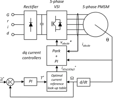
q q d d d d dt p L i di L Ri v1 = 1 + 1 1 − Ω 1 1 (1) + Ω + + = q q d d d f q dt p L i di L Ri v1 1 1 1 1 1 2 1 5 ψ (2) q q d d d d dt p L i di L Ri v 3 3 3 3 3 3 = + +3Ω (3) + Ω + + = q q q d d f q dt p L i di L Ri v3 3 3 3 3 3 3 2 5 3 ψ (4) + − = d q d q f q em p L L i i i T 1 1 1 1 1 1 1 2 5 ) ( ψ (5) + − = d q d q f q em p L L i i i T 3 3 3 3 3 3 3 2 5 3 ) ( 3 ψ (6) 3 1 em em em T T T = + (7) PI d/dt θ Optimal current reference look-up table Ω* Ω + -T* iabcde Rectifier 5-phase VSI 5-phase PMSM G r i d dq current controllers id1q1d3q3* Park + PI vabcde*
Fig. 1. Proposed control scheme
III. CONTROL STRATEGY
A. Implemented Control scheme
Fig. 1 shows the implemented control scheme. The speed is controlled using a PI controller and generates a torque reference. From this torque reference and the actual speed, dq current references are generated. The speed is estimated from the position measured by a synchro resolver and dq current reference data are stored in 2D look-up tables. Current references are compared to dq currents, estimated from the measured real currents transformed by T expressed by (8). All current data are obtained using numerical computations discussed in the next section.
Finally, dq currents are controlled by PI controllers and, using inverse transformation of T, generate voltage references which are sent to a five-phase voltage source inverter.
+ + − − + + − − + + − − + + − − = ) 5 2 ( 3 cos ) 5 4 ( 3 cos ) 5 4 ( 3 cos ) 5 2 ( 3 cos ) ( 3 cos ) 5 2 ( 3 sin ) 5 4 ( 3 sin ) 5 4 ( 3 sin ) 5 2 ( 3 sin ) ( 3 sin ) 5 2 cos( ) 5 4 cos( ) 5 4 cos( ) 5 2 cos( ) cos( ) 5 2 sin( ) 5 4 sin( ) 5 4 sin( ) 5 2 sin( ) sin( 2 1 2 1 2 1 2 1 2 1 5 2 π θ π θ π θ π θ θ π θ π θ π θ π θ θ π θ π θ π θ π θ θ π θ π θ π θ π θ θ p p p p p p p p p p p p p p p p p p p p T (8)
B. Comparison to existing methods
The computation of the current references in the flux-weakening zone is a difficult task. In order to be able to find analytical solutions to this problem, classical assumptions that are found in the literature are summarized:
- Stator resistances are neglected
- Saliency torque is not exploited (id currents are set to
zero below the base speed)
- To determine the maximum required voltage, it is assumed that harmonic voltage references (one and three in our case) reach their peak values in the same time instant, i.e. only magnitudes are considered disregarding the phase angles
All these assumptions lead to a non-optimal exploitation of intrinsic performances. Since it is very difficult to obtain an analytical solution to the problem without considering the former assumptions, in the next section a numerical computation of optimal references is proposed.
C. Computation of optimal dq current references
The optimal current reference data, stored in look-up tables, are obtained in three steps. All steps use numerical optimization tools (fmincon from the MATLAB Optimization Toolbox in this paper) which make possible to maximize or to minimize a function under constraints. No other assumptions than the ones proposed in section II are considered.
The first step consists in finding the speed limits and to compare them to the desired maximum speeds (negative and positive). When the computed speed limits are superior to the maximum desired speeds, the second step is started. The function to be maximized is expressed by (9).
( ) ( ) ≤ ≤ Ω max 2 max I i to i V v to v that such e a bus e a (9)
The second step consists in computing the boundaries of torque-speed characteristics (negative and positive). The function to be maximized is expressed by (10).
( ) ( ) ≤ ≤ max 2 max I i to i V v to v that such T e a bus e a em (10)
The third and last step consists in finding several (id,iq) sets
for torque and speed which are comprised between torque and speed limits. The function to be maximized is expressed by (11). ( ) ( )
(
)
( ) = + + + = ≤ ≤ ref em em q d q d losses e a bus e a losses T T i i i i R C I i to i V v to v that such C 2 3 2 3 2 1 2 1 max 2 min (11)IV. SIMULATION AND EXPERIMENTAL RESULTS
A. Machine parameters
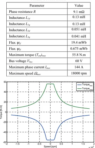
The five-phase machine is a permanent magnet synchronous machine prototype which has been developed for the project MHYGALE proposed by Valeo. All parameters are summarized in Table I. It has to be noticed that due to its particular structure, the machine possesses a small saliency only related to the third harmonic.
Fig.2 shows the boundaries of torque-speed characteristics that have been computed using step 2 of the proposed method. The base speed is evaluated at 1500 rpm. Below the base speed, the maximum torque is equal to 55.8 N.m.
TABLE I MACHINE PARAMETERS Parameter Value Phase resistance R 9.1 mΩ Inductance L1d 0.13 mH Inductance L1q 0.13 mH Inductance L3d 0.051 mH Inductance L3q 0.041 mH Flux ψ1f 19.4 mWb Flux ψ3f 0.675 mWb
Maximum torque (Tem)max 55.8 N.m
Bus voltage Vbus 60 V
Maximum phase current Imax 144 A
Maximum speed Ωmax 18000 rpm
-2 -1.5 -1 -0.5 0 0.5 1 1.5 2 x 10⁴ -60 -40 -20 0 20 40 60 Speed [rpm] Torque [ N .m ] Torquemin Torquemax
Fig. 2. Computed boundaries of torque-speed characteristics
B. Experimental validations
The proposed current references have been computed and tested on a five phase PMSM supplied by a five-leg VSI. Fig.3 shows a snapshot of the experimental setup which has been recently developed for MHYGALE project.
For practical reasons, the DC bus has been reduced to 30V and the maximum phase current to 25 A. Under these conditions, the base speed is equal to 98 rad/s, the maximum speed to 127 rad/s and the maximum torque to 9.6 N.m.
The analysis of the different idq currents for a given speed
and torque is difficult since there are several functioning zones where the objectives are different. The currents’ behaviours depend on the mechanical speed (below and above the base speed) and the peak phase currents (before their have reached the maximum and when they have reached the maximum).
Below the base speed (Ω<98 rad/s)
i1d and i3d are almost equal to zero since there is no need
for weakening the machine flux and the machine is quasi non salient.
o Below the current limit (ipeak<25A)
To analyse iq currents, please refer to Fig.4, which shows
the ratio between i3q and i1q for different torque references
(from zero to max) below the base speed (for example 50 rad/s). For a torque between 0 and 7.8 N.m, peak phase currents do not reach the maximum value and the ratio
q
q i
i3 1 is equal to 3λ3f λ1f (in that case equal to 0.104), leading to a given torque under minimum copper losses [7]. Torques Tem1 and Tem3, respectively associated with the first
and the third harmonics, are both positives.
See Fig.8 and Fig.9 for experimental results below the base speed and when the peak phase current is below the maximum.
o At the current limit (ipeak=25A)
When peak phase currents reach the maximum (for a torque equal to 7.8 N.m), ratio iq3 iq1progressively falls to -0.156 to fully exploit the current limit (see Fig.5). A negative ratio means that the third current harmonic is minimum when the first current harmonic is maximum, leading to the well-known case of a third harmonic injection when the first harmonic of a variable has to be maximum. In that case, it has to be noticed that torque Tem3 is negative along with a positive
torque Tem1 . The optimality is then to fully exploit the current
limit instead of minimizing the copper losses for a given torque.
See Fig.10 and Fig.11 for experimental results below the base speed and when the peak phase current is equal to the maximum.
Above the base speed (Ω>98 rad/s)
i1d and i3d are different from zero since there is need for
weakening the machine flux and the machine is quasi non salient.
o Below the current limit (ipeak<25A)
As shown in Fig.5 i1d is negative whereas i3d is positive
since it is the optimal way to reduce the peak phase voltage and then keeping the torque constant although the base speed has been reached. The peak phase current grows since i1q
stays constant.
See Fig.12 and Fig.13 for experimental results above the base speed and when the peak phase current has not been reached.
o At the current limit (ipeak<25A)
As shown in Fig.5 and Fig.7, when the peak current reaches his limit, slopes of idq currents change rapidly in order
to shift current harmonics one and three to optimally exploit the current limit. The torque decreases since iq currents
cannot be kept as they were before.
V. CONCLUSION
This paper presents an method to generate optimal current references in order to get the maximum torque of a multi-phase machine while using at their maximum the bus voltage and the phase currents. In order to validate the proposed method, a salient five-phase permanent magnet machine with non-sinusoidal Electro-Motive Forces has been tested below and in the flux-weakening region. Experimental results prove the effectiveness of the proposed method and show how can be used the extra degrees of freedom offered by multi-phase machines to fully exploit machine’s capabilities. Future improvements as high order harmonic injection and feedback scheme to cope with parameter variation are in progress.
ACKNOWLEDGMENT
This work is part of the project ’MHYGALE’ (Mild Hybrid for Generalization) with funding by ADEME (French Agency for Control and Saving Energy) within Valeo Engine Electrical Equipment.
REFERENCES
[1] Parsa, L.; , "On advantages of multi-phase machines," Industrial Electronics Society, 2005. IECON 2005. 31st Annual Conference of IEEE , vol., no., pp. 6 pp., 6-10 Nov. 2005
[2] Li Lu; Semail, E.; Kobylanski, L.; Kestelyn, X.; , "Flux-weakening strategies for a five-phase PM synchronous machine," Power Electronics and Applications (EPE 2011), Proceedings of the 2011-14th European Conference on , vol., no., pp.1-7, Aug. 30 2011-Sept. 1 2011
[3] L.Parsa, Kim Namhun, H.A.Toliyat, ‘‘Field Weakening Operation of High Torque Density Five-Phase Permanent Magnet Motor Drives’’, Proceedings of 2005 IEEE International Conference on Electric Machines and Drives (IEMDC2005), pp. 1507-1512, 2005.
[4] D.Casadei, M.Mengoni, G.Serra, A.Tani, L.Zarri, L.Parsa, ‘‘Control of a High Torque Density Seven-phase Induction Motor with Fieldweakening Capability’’, Proceedings of 2010 International Symposium on Industrial Electronics (ISIE2010), pp. 2147-2152, 2010. [5] E. Levi, D. Dujic, M. Jones, G. Grandi "Analytical Determination of
DC-Bus Utilization Limits in Multiphase VSI Supplied AC Drives", IEEE Trans. on Energy Conversion, Vol. 23, No. 2, June 2008, pp.433-443.
[6] Song Xuelei; Wen Xuhui; Cong Wei; , "Research on field-weakening control of multiphase permanent magnet synchronous motor," Electrical Machines and Systems (ICEMS), 2011 International Conference on , vol., no., pp.1-5, 20-23 Aug. 2011
[7] Kestelyn, X.; Semail, E.; , "A Vectorial Approach for Generation of Optimal Current References for Multiphase Permanent-Magnet Synchronous Machines in Real Time," Industrial Electronics, IEEE Transactions on , vol.58, no.11, pp.5057-5065, Nov. 2011
[8] D. Casadei, D. Dujic, E. Levi, G. Serra, A. Tani, L. Zarri, “General Modulation Strategy for Seven-Phase Inverters with Independent Control of Multiple Voltage Space Vectors,” IEEE Trans. on Industrial Electronics, Vol. 23, No. 2, May 2008, pp.1921-1932.
Fig. 3. Snapshot of the experimental test bed 1 2 3 4 5 6 7 8 9 10 -0.1 -0.05 0 0.05 0.1 Cem (N.m) iq3/ iq 1
Fig. 4. (i3q/i1q) versus torque below the base speed (at 50 rad/s)s
0 20 40 60 80 100 120 -50 -40 -30 -20 -10 0 10 20 30 speed (rad/s) Cu rr en ts (A ) id1 iq1 id3 iq3
Fig. 5. dq currents versus speed for a torque equals to 1N.m
0 20 40 60 80 100 120 0 5 10 15 20 25 30 Speed (rad/s) vpeak ipeak cem
Fig. 6. Voltage phase peak, current phase peak and torque versus speed for a torque refrence equals to 6N.m
0 20 40 60 80 100 120 -1.5 -1 -0.5 0 0.5 1 1.5
Mechanical speed [rad/s]
C u rr ent s [ p u] Id1 Iq1 Id3 Iq3 0 1 2
Fig. 7. dq current references versus speed for a maximum torque and maximum phase current
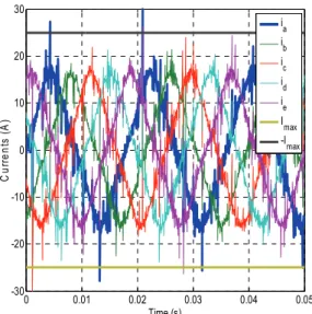
0 0.01 0.02 0.03 0.04 0.05 -30 -20 -10 0 10 20 30 Time (s) C u rr ent s ( A ) ia ib ic id ie Imax -Imax
Fig. 8. Experimental phase currents for 5 N.m at 50 rad/s
0 0.01 0.02 0.03 0.04 0.05 -20 -15 -10 -5 0 5 10 15 20 Time (s) Vol tage s ( V ) va vb vc vd ve -Vbus/2 Vbus/2
Fig. 9. Experimental phase voltages for 5 N.m at 50 rad/s
0 0.005 0.01 0.015 0.02 0.025 0.03 0.035 0.04 0.045 -30 -20 -10 0 10 20 30 Time (s) C u rr e n ts (A ) ia ib ic id ie -Imax Imax
Fig. 10. Experimental phase currents for 9.6 N.m at 50 rad/s
0 0.005 0.01 0.015 0.02 0.025 0.03 0.035 0.04 0.045 -20 -15 -10 -5 0 5 10 15 20 Time (s) V o ltag es ( V ) va vb vc vd ve -Vbus/2 Vbus/2
Fig. 11. Experimental phase voltages for 9.6 N.m at 50 rad/s
0 0.005 0.01 0.015 0.02 -30 -20 -10 0 10 20 30 Time (s) C u rre n ts (A ) ia ib ic i d i e -Imax Imax
Fig. 12. Experimental phase currents for 5 N.m at 115 rad/s
0 0.005 0.01 0.015 0.02 -20 -15 -10 -5 0 5 10 15 20 Time (s) V o lta g es ( V ) va vb vc vd ve -Vbus/2 Vbus/2