Science Arts & Métiers (SAM)
is an open access repository that collects the work of Arts et Métiers Institute of
Technology researchers and makes it freely available over the web where possible.
This is an author-deposited version published in:
https://sam.ensam.eu
Handle ID: .
http://hdl.handle.net/10985/17437
To cite this version :
L. GODINO, I. POMBO, Jérémie GIRARDOT, J.A. SANCHEZ, Ivan IORDANOFF - Modelling the
wear evolution of a single alumina abrasive grain: Analyzing the influence of crystalline structure
-Journal of Materials Processing Technology - Vol. 277, p.116464 - 2020
Any correspondence concerning this service should be sent to the repository
Administrator :
archiveouverte@ensam.eu
Modelling the wear evolution of a single alumina abrasive grain: Analyzing
the influence of crystalline structure
L. Godino
a,⁎, I. Pombo
a, J. Girardot
b, J.A. Sanchez
a, I. Iordanoff
baFaculty of Engineering Bilbao, University of the Basque Country (UPV/EHU), Plaza Torres Quevedo, 1, 48013 Bilbao, Spain bArts et Métiers ParisTech Centre de Bordeaux-Talence, Esplanade des Arts et Métiers, 33400 Talence, France
Keywords: Grinding Abrasive grains Wear model DEM Alumina SG A B S T R A C T
The grinding process is continuously adapting to industrial requirements. New advanced materials have been developed, which have been ground. In this regard, new abrasive grains have emerged to respond to the de-mands of industry to reach the optimum combination of abrasive-workpiece material, which allows for both the minimization of wheel wear and increased tool life. To this end — and following previous experimental works — the present study models in 3D the wear behavior of Sol-Gel alumina abrasive grain using Discrete Element Methods. It is established that the alumina behaves as a ductile material upon contact due to the effect of high temperature and pressure. This model reproduces the third body generation in the contact, taking into account the tribochemical nature of the wear flat, which is the most harmful type of wear in the grinding process. The evolution of the wear during a complete contact is analyzed, revealing similarities in the wear of white fused alumina (WFA) and Sol-Gel (SG) alumina. However, the SG abrasive grain suffers less wear than the WFA under the same contact conditions. The proposed wear model can be applied to any abrasive-workpiece combination.
1. Introduction
The grinding process is continuously improving due to the constant research efforts aimed at satisfying industrial demands, along with the need to be competitive with respect to other manufacturing processes. New industrial requirements related to an increased efficiency of the grinding process and quality of the ground surfaces demand that the process should continue to be adapted. Further, advanced materials need to be ground in a manner that meets all of these industrial re-quirements. Thus, recent years have seen the development of abrasives and grinding wheels aimed at increasing tool life and removal rates in order to improve processing efficiency and reduce costs. The develop-ment of microcrystalline sintered alumina created a new generation of abrasives, and due to the increased importance of this kind of abrasive during the last year,Nadolny (2014)produced a state of the art review summarizing the properties and industrial application of microcrystal-line alumina. This type of crystalmicrocrystal-line structure is currently the subject of considerable research aimed at achieving improvements that allow these materials to compete with super-abrasives in more critical op-erations.
With respect to wheel life, microcrystalline Sol-Gel alumina (SG) is more durable and efficient than conventional white fused alumina (WFA), with the particularity of self-sharpening due to the
micro-crystals of 0.1–5 μm in size, which are randomly oriented. However, the behavior of SG abrasive grains under heavy grinding conditions is yet to be completely characterized. Moreover, to ensure the optimum design and application of microcrystalline grinding wheels, a more in-depth analysis is needed with respect to the contact and wear mechanisms that occur during grinding. Thus, in recent years, various research studies have been conducted in order to analyze the behavior and wear of microcrystalline abrasive grains. The majority of works are focused on the behavior of polycrystalline CBN abrasive grains for aeronautics applications. In this sense,Zhu et al. (2019)affirm the attritious wear on polycrystalline CBN abrasive grains due to the chip adhesion and micro-fracture of the grain due to crack propagation. Meanwhile, the analysis of wear of CBN abrasive grains is widely studied.Zhao et al. (2019)analyze the wear evolution on CBN abrasive grains showing wear flat areas in the first states, micro cracks at the middle of the tests and after 20,265 mm3of work piece material removed the grain breaks
totally.
Regarding to microcrystalline alumina behavior during the real grinding process, the studies are addressed from different perspectives. For instance,Mayer et al. (2006)analyzed the behavior of SG alumina by conducting tribological tests. In contrast,Nadolny (2015)analyzed SG alumina abrasive grains during internal cylindrical grinding, whilst Godino et al. (2018a)carried out the most recent study analyzing the
⁎Corresponding author.
E-mail address:leire.godino@ehu.eus(L. Godino).
https://doi.org/10.1016/j.jmatprotec.2019.116464
influence of the crystalline structure on abrasive grain wear. To this end, experimental tests specifically designed to promote wear flat were conducted. Thus, these three works show the critical importance of the crystalline structure for both the tool life and the general efficiency of the grinding process.
Tool life is directly related to grinding wheel wear, which produces dimensional, geometrical, or surface quality errors, leading to rejected parts and, consequently, economic losses. Among the various types of wear, the occurrence of wear flat leads to the most damaging impact on the work piece, i.e. thermal damage. Moreover, wear flat is of a tribo-chemical nature, with temperature and the work piece-grain material combination both playing a key role in the process, which hinders the study of wear flat. Thus,Malkin and Cook (1971)analyzed the evolu-tion of wear flat by examining the influence of wheel hardness or the effect of dressing on monocrystalline alumina. Many years later, Nadolny (2015)conducted grinding tests to analyze all types of wear that occur on the SG grinding wheel, including wear flat. However, the evolution of these processes cannot be analyzed due to the influence of other types of wear.Xi et al. (2018)also analyze the evolution of wear flat comparing silicon carbide and pink alumina grinding Ti2AlNb. This
work shows the importance of chemical reactions on wear flat gen-eration, being the wheel life of pink alumina grinding wheels 8 times larger than silicon carbide alumina. In general, the evolution of wear flat on microcrystalline grinding wheels has not been widely studied since SG abrasive grains are industrially categorized due to their ability to self sharpen. However, during real experimental grinding tests, Godino et al. (2018a) demonstrated that flatness of microcrystalline grinding wheels can occur, depending on the grinding parameters and wheel conditioning. The aim of this work was to analyze the influence of the crystalline structure of the alumina on wear flat generation during a real grinding process. To this end, the wear flat was isolated from other types of wear. This work demonstrates the importance of both tribochemical reactions and third body generation in the evolution of wear flat, with one limitation being the exhaustive control of real contact conditions, particularly the monitoring of real pressure.
In order to control real contact conditions, pin on disk tests are widely used to carry out tribological studies. Thus,Mayer et al. (2006) analyzed the wear of microcrystalline alumina through pin on disk tests, demonstrating third body adhesion and plasticized alumina due to the high temperatures reached upon contact. Whilst this work was able
to achieve contact pressures close to those experienced during the grinding process (0.5–1.5 GPa) the tests were conducted at a very low sling speed (2 m/s). Moreover, this author confirmed that the micro-crystalline alumina present lower thermal conductivity than conven-tional alumina. With the aim of addressing the two limitations of Mayer´s work, along with the randomness of the grinding process, Godino et al. (2018b)examined the wear of alumina abrasive grains from a tribological point of view. The new design of pin on disk tests allows for monitoring contact conditions and reproducing the real contact of abrasive grains, along with their thermal cycle. This test bench reaches 190 MPa and 30 m/s and shows the initial and final states of the wear, but presents the limitation of being unable to analyze the complete evolution of wear generation. Thus, in order to address the current gaps in knowledge regarding wear flat evolution and to provide a more in-depth understanding of the influence of the crystal-line structure on wear flat generation, in the present study the analysis of wear flat is addressed from a numerical point of view.
As described previously, from an experimental point of view, the analysis of wheel wear presents a number of limitations. In general, these challenges are related to process monitoring, particularly tem-perature measurement in the contact or wear quantification during the process, among others. In order to address these experimental diffi-culties, numerical simulations are useful tools for better understanding certain phenomena that occur during the real process. In general, the aim of wheel wear models is to characterize the wear and the ex-pectancy of the wheel life. Moreover,Brinksmeier et al. (2006) con-ducted several studies analyzing the importance of the simulation and modeling of wheel wear for process optimization. In this regard, con-siderable efforts have been directed towards developing 2D and 3D wheel topography models, taking into account abrasive grain shape and size, the random distribution of the wheel matrix, and dressing me-chanics accounting for fracture and deformation leading to a dressed surface.Chen and Rowe (1996)developed the first study to model the topography of the grinding wheel surface. Later,Badger and Torrance (2000)developed a model for accurately predicting grinding forces. In this work, grinding wheel topography was also modeled. Both of these studies simulate grinding wheel topography, but the wear of the grinding wheel was not considered. In contrast, Jiang et al. (2013) developed a mathematical model in order to predict the wheel topo-graphy and roughness of the ground work piece. This model took into
Nomenclature
C [-] Failure constant COR [-] Coefficient of restitution cp [J/kgK] Specific heat capacity DE [-] Discrete Element DEM [-] Discrete Element Method
E = EM[GPa] Young´s modulus or Macro Young´s modulus,
corre-sponding to real properties
Eμ[GPa] Micro Young´s modulus, calibrated Young´s modulus of
beams in DEM FEM [-] Finite Element Method
Fnμ[N] Micro normal force correspondent to a single DE
Ftμ[N] Micro tangential force correspondent to a single DE
K [W/mK] Thermal conductivity pr [MPa-GPa] Real Contact pressure qch[W/m2] Heat flux to the chip
qf[W/m2] Heat flux to the fluid
qg[W/m2] Heat flux to the grain
qt[W/m2] Total heat flux
qw[W/m2] Heat flux to the workpiece
Rw[-] Partition of heat that is directed to the workpiece
rμ[-] Ratio between cohesive beam radius and average DE
radius
s [m/s] Sliding speed
SG [-] Sol-Gel alumina, microcrystalline structure
tc[s] Contact time
VM[m3] Macro volume: volume of the real body
VμiVμ[m3] Volume of one DE or Discrete volume of the modeled
body
WFA [-] White Fused Alumina, conventional structure γ [-] Adhesion parameter in DEM
κ[-] Stiffness parameter in DEM
μ [-] Friction coefficient
μμ[-] Micro friction coefficient, corresponding to friction
be-tween DEs in DEM
νM[-] Poisson´s ratio or macro Poisson´s ratio, corresponding to
real properties
νμ[-] Micro Poisson´s ratio: calibrated Poisson´s ratio of beams
in DEM
ρ=ρM[kg/m3] Density or Macro density, corresponding to real
properties
ρμ[kg/m3] Micro density: calibrated density of beams in DEM
σfμ[MPa] Micro failure stress of DEM beams
account both the wheel topography dressing effect and the effect of wear.
Similarly, both the randomness of wheel topography and the char-acteristics of abrasive grains hinder simulation of the complete grinding wheel. Thus, the most common models related to grain work piece contact are simplified, with single grain contact, and are generally developed using finite element methods as mentioned byAurich et al. (2009)in their review of the modeling and simulation of the grinding process. In general, the main objective of these works is usually to characterize material removal mechanisms, without considering the wear suffered by the abrasive grain. Over the years, different shapes of abrasive grains have been modeled. For instance,Koshy et al. (1997) modeled spherical abrasive grains, after which Cooper and Lavine (2000)modeled the abrasive grains using a pyramidal shape whilst, in contrast,Rasim et al. (2015)simulated conical abrasive grains. On the basis of these works, it is concluded that the spherical grain is appro-priate for reproducing the radius and the slope since the inclination changes depending on the depth of the abrasive grains.
Moreover, different wear types have been modeled.Yu et al. (2017) have divided the wear into two phases, with grain pull out being con-sidered in the first phase and the combination of wear flat and grain fracture considered in the second phase. Moreover,Adibi et al. (2013) modeled wheel loading. This model is based on the adhesion of work piece material to CBN abrasive grains. This analytical model predicts a high dependence of wheel loading on the depth of cut and cutting speed. With regard to wear flat,Hwang et al. (2000)developed statis-tical tests to determine both active grain density and wear flat area. In this work a pyramidal grain shape is assumed for diamond abrasive grains, achieving a linear relationship between grinding forces and wear flat area. Almost all the models were developed for CBN or dia-mond abrasive grains, and wear flat values can more readily be mea-sured to validate the simulation and to determine the active grains of the surface. In contrast, when using conventional abrasive grains, these two aspects hinder the characterization. In recent years, Ardashev (2015)have developed a mathematical model to determine the flat area by taking into account mechanical and physicochemical reactions. In this study the conical shape of alumina abrasive grains was modeled. The formulation is carried out in relation to the loss of grain weight due to both the mechanical interaction and chemical affinity with the ma-terial in contact. However, this approach does not take into account the crystalline structure of the alumina or the adhesion of the third body to flat areas. In general, wear and wheel topography is modeled and nu-merical simulations are carried out. Also, experimental works mea-suring wheel topography or wheel wear are analyzed. However, after a deep analysis of the bibliography, it is missed works comparing both experimental and numerical wear and wheel topography results.
Regarding to the method, DEM is used for modeling different phy-sical states taking into account all the interactions between two parti-cles or between a particle and geometries. Moreover, Maheo et al. (2015) demonstrated that DEM is suitable to model discrete media, being a very useful for composite modeling. In this sense, a single abrasive grain composed by different crystals can be well reproduced using DEM. In contrast FEM is more suitable to reproduce continuous materials. Likewise, Ardashev (2015), developed a cohesive beam model of DEM, allowing also the simulation of continuous materials, without miss the particularity of its discontinuities. This fact becomes a DEM on a suitable approach for the wear and fracture simulation of a single abrasive grain.
Apart from this, the contact between two bodies has been studied using both FEM and DEM. The models developed using FEM are gen-erally based on Archard wear law,Archard (1953). However, one of the handicaps of FEM is that once the material is detached from one of the bodies, is no longer taken into account. However, in a real contact, once the material is detached the third body generated is retained between the first two bodies in contact. The adhesion force is the responsible of maintain the third body in the contact. Moreover, DEM allows
maintaining also the third body in the contact, being the adhesion forces well represented. In this sense, firstlyIordanoff et al. (2002) developed a model using the Discrete Element Approach (DEM) to re-produce tribological contact between two bodies. Later,Fillot et al. (2007) developed a more accurate model in which the third body generation in the contact and the adhesion of the third body is con-sidered. In parallel, abrasive processes, from polishing to grinding are studied using DEM.Goupil et al. (2013)modeled polishing using dis-crete media taking also into account the wear in the contact. Moreover, Blaineau et al. (2015)studied abrasive processes using DEM andOsa et al. (2016)modeled a grinding wheel which present heterogeneous matrix, composed by pores, grains and bond. Furthermore, in the contact between abrasive grains and workpiece, adhesion, abrasion and fracture can be represented using DEM.
Thus, two mean reason make suitable Discrete Element Approach (DEM) to reproduce abrasive grain-workpiece contact. On the one and an important characteristic of DEM is the relative ease with discrete elements can be detached for comparison with FEM. On the other hand DEM is suitable for wear characterization taking into account the in-fluence of the third body in the contact. In contrast FEM cannot si-mulate the third body in the contact ones the material is removed from the body. Therefore, in the present research work DEM is going to be used to simulate the contact between abrasive grains and the work-piece. Moreover, this model is going to be capable to reproduce the third body, the wear and its influence on the contact.
In summary, the evolution of wear flat on alumina abrasive grains has not been addressed from a numerical point of view. The random-ness of alumina grinding wheels, the tribochemical reactions that lead to wear flat, and the continuously changing contact conditions all serve to hinder contact modeling. Moreover, third body generation is a factor that has not been taken into account for wear flat simulation in spite of the fact that it has considerable impact on the contact. Finally, there are no models that differentiate abrasive grain wear according to its crys-talline structure. The present study therefore aimed to address the limitations of previous experimental works by modeling the wear of a single alumina abrasive grain under real contact conditions. A ductile behavior of the alumina is established in the contact with the work piece due to the high temperature and high pressure. Thus, the effect of the heavy contact conditions is taken into account in the wear model. In previous experimental work only the initial and final states of wear could be analyzed, which hinders a complete analysis of wear behavior. In order to address this issue, we developed a discrete element wear model, revealing both the trend and evolution of wear during the entire period of contact. Moreover, the influence of the crystalline structure of alumina on the evolution of the wear is analyzed, comparing WFA and SG abrasive grains. In this model, the tribochemical nature of wear flat — and hence the generation of the third body in the contact and the changes produced due to its presence — are taken into account. In spite of the fact that the present work was developed for a specific combi-nation of abrasive grain and work piece material working under heavy contact conditions, the proposed wear model can be applied to any work piece-abrasive grain combination.
2. Basic assumptions
As it is previously mentioned, this numerical work is based on previous experimental analysis of alumina wear under real grinding conditionsGodino et al. (2018a,2018b). Firstly the wear was analyzed during grinding and secondly using a pin on disk tribometer. The data obtained from tests carried out pin on disk tribometer are going to be used in the present work. In these experimental tests real grinding contact conditions were reproduced controlling real contact area, real contact pressure and real sliding speed. Moreover, the intermittent contact between a single abrasive grain and the workpiece were re-produced. To this end, WFA and SG real grinding wheels were used a disk and AISI D2 of 64 HRc as a pin, with a contact area of 15 mm2.
Moreover, the disk topography was characterized in order to ensure the control of the contact area. InTable 1are built the main parameters and alumina wear results, which are going to be useful for the present nu-merical work.
Regarding to the numerical work, for simplicity, a single abrasive grain model is developed as a first approach to modeling the wear of alumina abrasive grains under real contact conditions. DEM is highly suited to the simulation of wear since discrete elements are easily de-tached from the initial body, whilst these discrete elements are also suitable for modeling the third body generation. Thus, the wear of a single abrasive grain is modeled using DEM. Since discrete elements are usually suitable for modeling discontinuous material, the discretization of the grain is useful for modeling wear and third body generation, since it behaves as a discontinuous material. However, alumina is a continuous material, and thus a 3D cohesive beam model is im-plemented to simulate the abrasive grain.André et al. (2012)developed the 3D cohesive beam model in GranOO C++ Workbench library. In this cohesive beam model, beams joining discrete elements (from now on DEs) acquire the properties of alumina grains, specifically the micro properties of the alumina. To achieve these properties, a calibration step is required to apply the mechanical parameters to the microscopic beam in order to achieve macroscopic behavior that is equivalent to that shown by alumina, as displayed inFig. 4. A spherical abrasive grain of 300 μm in diameter is modeled in order to validate the nu-merical wear model with pin on disk test results, as previously carried out byGodino et al. (2018b). A semi-sphere is modeled since more than 50% of the abrasive grain is embedded in a wheel matrix. This hy-pothesis offers the advantage of reducing computational costs whilst also enabling the application of model inputs.
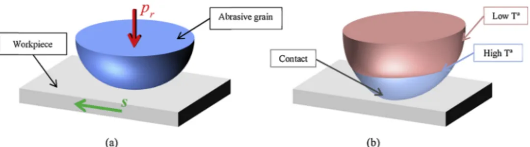
For the implementation of the wear model, the loads applied to the abrasive grain are also obtained from the tribological test, including sliding speed (s), and real contact pressure (pr), in order to validate the wear model with pin on disk test results. The two bodies in contact are shown in Fig. 1(a), which displays the alumina abrasive grain and hardened tool steel work piece along with the two model inputs. In a real contact the third body consists of particles detached from alumina and steel along with other compounds generated due to the chemical reactions. However, for simplicity, the hypothesis considered here as-sumes that the work piece is a non degradable body. Moreover, to consider the effect of temperature, the abrasive grain is divided into two zones, as shown inFig. 1(b). The contact, that is, the bottom zone (blue), reaches a higher temperature than the top zone (red). This distinction allows for including temperature in the DE model without the development of a thermal DE model. Finally, the wear of WFA and SG alumina are simulated. The thermal and mechanical properties differ according to the crystalline structure and the purity of the alu-mina. For this work, alumina properties are obtained from the work published byIncropera et al. (2007)whilst for WFA and SG the same properties are used and the differences are established with the fol-lowing assumptions:
•For the thermal model, the heat source of WFA or SG abrasive grain is calculated using the tribometer data, so that a different level of heat is imposed in each case.
•For the wear model, the differences in behavior due to the crys-talline structure are defined in terms of failure criteria values.
3. Classification of two zones depending on the temperature in the grain
3.1. Definition and assumptions for the finite element thermal model
The 2D thermal model is developed using FEM with the software ANSYS® Mechanical APDL. Thermal analysis is carried out for both crystalline structures of the alumina abrasive grain in order to accu-rately determine the height of the bottom zone. To this end, the varia-tions in mechanical and thermal properties according to temperature are taken into account. As the temperature rises, thermal conductivity continuously decreases whilst the specific heat capacity continuously increases. For the thermal and wear model the hypothesis of observing differences in behavior at a temperature of 200 °C is assumed. The height corresponding to 200 °C isotherm is determined in the abrasive grain, and this value of height defines the 2 zones. It is assumed that the alumina behaves similarly from room temperature up to 200 °C, de-fining the top zone and acquiring the properties at room temperature. In contrast, from 200 °C the changes in the properties of the alumina lead to changes in its behavior, even showing behavior similar to that of ductile material just at the moment of contact, when the highest tem-peratures are reached. This affirmation is done becauseMayer et al. (2006)concluded the alumina in the contact present plastic flow. Thus, the bottom zone is defined from 200 °C up to the maximum temperature and acquires the properties of the maximum temperature. Properties of alumina with a conventional crystalline structure and purity of 98% are used for the present work and are built inTable 2.
The objective of the 2D thermal model is to determine the height of 200 °C isotherm and the maximum temperature in the contact. To this end, a single abrasive grain of 350 μm diameter is modeled and the contact distance between the grain and the workpiece is calculated following the approach adopted byMalkin and Guo (2008), being in this case 35 μm, as shown in red inFig. 2(b). In this length the heat source is applied, which is calculated using pin on disk test results following Eq.(1).Fig. 2(a) shows the heat distribution in grinding. For this model the heat flux corresponding to the chip and the fluid is 3 orders of magnitude lower than for heat flux to the grain and two orders of magnitude lower than for the heat flux to the workpiece. Thus, for simplicity, hchand hfare negligible for the present work, as shown in
Eq.(2). Likewise, the heat flux of the workpiece is also expressed as in Eq.(3). The partition of heat that is directed to the workpiece, Rw, has
been widely studied by a number of authors, varying from 0.25 to 0.9 depending on the wheel, workpiece materials, and grinding kinematics. For the case being studied here, a single abrasive grain sliding against hardened steel is evaluated, with ploughing and rubbing being the wear mechanisms that take place.García (2014)analyzed Rwaccording to
the crystalline structure of the alumina, showing Rw= 0.48 for WFA
abrasive grains and Rw= 0.54 for SG alumina. These values are used in
the present thermal study in order to calculate qgas shown in Eq.(4).
Input values for the thermal model are determined on the basis of the tribometer data. = = q P A F s A t r t r (1) = + + + + qt qw qg qch qf qw qg (2) = qw R qw t (3) = qg (1 R qw) t (4)
Heat source, ambient temperature, and the effects of the coolant are the boundary conditions of the thermal model as shown inFig. 2(b). A constant heat transfer by convection is used h = 10,000 W/m2K on
grain free areas. The contact time is also a very important input for the thermal model. As in the case of heat flux, this value is obtained from the tribometer data and is listed inTable 3. Due to the short tcand the
high s, the intermittent contact of each abrasive grain is not considered Table 1
Pin on disk tests main resultsGodino et al. (2018).
Contact time[s] Pressure [MPa] Wear Height [μm]
WFA SG WFA SG
20 m/s 5.25 118 185 23 17
25 m/s 0.92 112 168 23 17
in the thermal model. Finally, the mesh is defined using a front feed method, which is an automatic methods that obtain the final mesh, element by element, from the definition of the contour. Moreover, for this model, around the contact a fine mesh is established, being the size of the triangular elements about 1 μm, whilst in the center of the grain the coarse mesh is defined, being about 3 μm the size of the elements, as shown inFig. 2(b).
3.2. Results of 2D thermal simulations
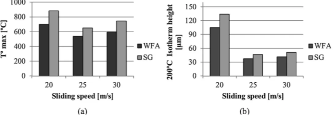
A total of six simulations were carried out, three for each crystalline structure, at different sliding speeds, as shown in Table 3. Fig. 4(a) shows that very similar results are obtained for 25 and 30 m/s and a higher temperature for 20 m/s, whilst it is clear fromFig. 4(b) that for 20 m/s the isotherm height is higher than 100 μm, and for 25 and 30 m/ s it is lower than 50 μm. The distribution of the temperature inside the abrasive grain is shown inFig. 3. Similarly, when considering the in-fluence of the crystalline structure, the greatest height is achieved for the SG abrasive grain in comparison with WFA. The maximum tem-perature is approximately 900 °C for 20 m/s and between 550 and 700 °C for 25 and 30 m/s.
When analyzing the influence of the crystalline structure, higher temperatures are reached for the SG abrasive grain (approximately 100 °C). These results indicate that the initial hypothesis used to cal-culate the heat flux is correct given that the temperatures reached are in concordance with the thermal conductivity results obtained byMayer
et al. (2006). The maximum temperature reached is lower than that obtained in real grinding because the simulated contact time is shorter than that observed in a real process. Therefore, there is insufficient time to achieve such high temperatures. When comparing the results of the different tests, a higher temperature is reached in the case of 20 m/s. Thus, the sliding speed has an influence on the temperature reached in the alumina abrasive grain, leading to the conclusion that this finite element model reveals the influence of sliding speed on the achieved temperature and hence on the wear of the abrasive grain.
Fig. 1. (a) Scheme of contact modeling, showing two bodies in contact and the model inputs. (b) Two-zone classification according to temperature. Table 2
Conventional alumina properties at different temperatures, Incropera et al. (2007). Room Tª 200 °C 650 °C Density [kg/m3] 3900 3900 3900 K [W/mK] 37 20 9 Cp[J/kgK] 780 1046 1225 E [GPa] 385 370 343 Poisson´s ratio ν 0.22 0.22 0.22
Fig. 2. (a). Heat distribution in grinding, (b) abrasive grain boundary conditions, and grain mesh. Table 3
Input parameters for the 2D thermal model.
Sliding speed [m/s] 20 25 30
Contact Time [ms] 5.25 0.92 0.85
qg[W/m2] WFA 304.6 337.7 384.3
qg[W/mm2] SG 386.7 413.9 483.4
Fig. 3. Temperature distribution within the SG abrasive grain for 30 m/s.
Finally, to develop a discrete element model, the same height is used for 25 and 30 m/s tests since the difference in height is lower than 10%. The sliding speed of 20 m/s is not considered when developing the wear model. In contrast, differences due to the crystalline structure are taken into account when analyzing the wear of WFA and SG abrasive grains. Thus, the height of the isotherm at 200 °C for WFA is approximately 38 μm and for SG this is 47 μm. These values determine the height of the
bottom zone in the wear model.
4. Abrasive grain wear model
GranOO C++ Workbench is used to develop the abrasive grain wear model becauseAndré et al. (2014)showed in this work the ap-plicability of GranOO to simulate the tribological problems. The mod-ularity of GranOO, together with its explicit DEM code specialized in modeling continuous materials, allows for the simulation of an alumina abrasive grain.Fig. 5shows the flowchart that summarizes the simu-lation of the wear of the alumina abrasive grain using DEM. The Fig. 4. (a) Maximum temperature reached inside the abrasive grain, (b) the height of 200 °C isotherm.
simulation time is the real contact time, tc, defined inTable 3, varying
from 5.25 to 0.85 ms depending on the case being studied. The most important variables to adjust in the model are the micro failure stress of the beams (σfμ) and the adhesion parameter (γ), related to the third
body adhesion both on the abrasive grain and between third body particles.
4.1. Defining the discrete element wear model
As mentioned previously, a single abrasive grain sliding against a workpiece is modeled. The workpiece is modeled as a non-degradable and non-deformable first body, at a plane of 600 × 600 μm, positioned just in contact with the abrasive grain, as shown inFig. 6(a). The role of the workpiece in the model is to establish contact with the abrasive grain, with the purpose of imposing the sliding speed. In contrast, the abrasive grain is modeled as a degradable and deformable first body, forming a semisphere of Ø300 μm. The discretization of the abrasive grain is carried out using spherical DEs. In order to reproduce the continuous behavior of alumina material, a 3D cohesive beam model was imposed. Thus, the DEs comprising the abrasive grain are joined by beams. For generation of the grain, the radius values of the spheres are randomly chosen within a range of 25% around a mean value of the programmed radius of 3 μm, building a complete sphere of Ø300 μm. The abrasive grain is divided into two zones in order to consider the effect of temperature. InFig. 6(b) the height of the two zones and the pressure surface are shown for SG.
In the wear model, the following sets of DEs are defined: bottom
zone, top zone, pressure surface, and third body. The bottom zone acquires
the properties of alumina at the maximum temperature obtained in the thermal model, 650 °C. In contrast, the top zone acquires the properties of the alumina at room temperature. Table 2 lists the properties of alumina for the two zones, and from now on, these properties are re-ferred to as macro properties. Moreover, pressure surface is needed in order to apply pressure to the model. A flat and homogeneous surface just in the upper part of the semi-sphere is generated, halving the initial sphere. Finally, the third body set allows for implementing contact laws between DEs corresponding to the third body and the rest of the abrasive grain, with the workpiece, and even between third body DEs. It is worth noting that DEs corresponding to the third body are not con-nected by beams. In contrast, the adhesion force keeps the third body attached to the abrasive grain or to other third body DEs.
4.2. Calibration of alumina micro properties and failure criteria
Alumina is a continuous material, and DEM is well adapted to si-mulate discontinuities; therefore, a 3D cohesive beam model developed by André et al. (2012) is used in order to simulate this continuous material. Cylindrical beams are defined by geometrical (Lμ, rμ) and
mechanical properties (Eμ, νμ) which determine the behavior of the
beams.Fig. 7(a) shows the scheme of the cohesive beam configuration. These micro properties have to be calibrated by carrying out virtual tensile tests. Unlike the mechanical and geometrical properties, the
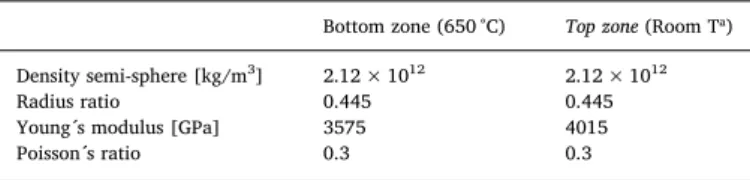
beams do not have a mass, and this is imposed on the discrete elements and calibrated with the real volume and density of the system. For the present study, the mass of a complete grinding wheel (10 kg) is sidered in the volume of a single abrasive grain (Ø300 μm). This con-sideration is needed when applying force because the most influential parameter in the model is mass. The calibration is conducted following the steps established byAndré et al. (2012). For Eμ,νμ and ρμ and for the two zones, the results are listed inTable 4. In contrast, the calibration of failure stress is not carried out using a virtual tensile test, as in the two previous mentioned worksAndré et al. (2014,2012).
The hypothesis set out in this work is that the wear of the abrasive grain occurs when the DEs are detached from the initial first body, that is, when the third body is generated. It is established that one DE is detached from the first body if every beam connecting this DE with the rest of the body breaks, as shown inFig. 7(b). At this moment the third body, the wear, is generated, asFig. 7(c) shows, and an adhesion force is imposed on detached DEs in order to simulate the effect of the third body adhered to the worn abrasive grain. The failure criterion that is imposed on the beams is the maximum micro failure stress. Therefore, the behavior of alumina is modeled with the failure stress of the beams. In this regard, differences in behavior according to the crystalline structure are modeled, imposing different levels of failure stress. For the case studied here, first the failure stress for WFA abrasive grains is achieved after which this value is adjusted to reproduce the wear of SG abrasive grains.
With regard to failure stress, it is assumed that beams corresponding to the top zone are unbreakable because the temperature does not have any influence. In contrast, the bottom zone is affected by high tem-peratures on contact, leading to modifications in the behavior of the alumina. Thus, it is considered that the bottom zone behaves in the same way as ductile material, as it is concluded in the work carried out by Mayer et al. (2006). To implement this hypothesis in the model the Von Mises yield criterion is introduced, and the ductile failure criterion using Von Mises is implemented in GranOO workbench. Von Mises criterion for the beams is defined in Eq.5, where σ is the normal tension of the beam and τ is the tangential tension. Therefore, the failure cri-terion for the wear model is defined using Von Mises stress (σvm) as
followed in Eq.(6). The beam breaks if micro failure stress (σfμ) reaches
σvm. Moreover, for this wear model an alternative to calibrate σfμ is
developed without the need to quantify macro failure stress. In tri-bology, it is accepted that the generated third body corresponds to wear. Therefore, in this wear model it is assumed that the generated third body is equivalent to the wear suffered by alumina on pin-on-disk tests. So, for the present wear model, σfμ is calibrated comparing the
third body generated in the numerical model with the wear measured on the pin-on-disk tribometer tests.
= + 3
vm 2 2 (5)
>
If vm fµthe beam breaks (6)
4.3. Model inputs and boundary conditions
Sliding speed and pressure are the model inputs. The modeled sliding speed is 30 m/s. To this end, a Coulomb law simplification is used because it is a high sliding speed and the static friction coefficient does not affect the contact in the case studied here. Therefore, a constant dynamic friction coefficient is assumed during a complete contact, i.e. the micro friction coefficient (μμ). This coefficient is different from a macro friction
coeffi-cient that is achieved during the tests. Moreover, the sliding speed is im-posed as a micro tangential force (Ftμ= μμFnμ) applied to each DE in
contact with the workpiece, asFig. 8(a) shows. Thus, it is necessary to achieve the optimal μμrepresentative of 30 m/s sliding speed.
To impose the pressure on the abrasive grain a simplification of the force application is carried out, with the most influential parameter being the mass of the complete system, as previously explained. The force is applied homogenously due to the pressure surface, as shown in Fig. 8(b). The value of the applied force is calculated with the real pressure obtained on pin-on-disk tribometer tests, which is approxi-mately 105 MPa for WFA and 160 MPa for SG abrasive grains.
The abrasive grain is embedded in a wheel matrix. Therefore, to avoid free movements of the abrasive grain due to Ftμ, the movement of
DEs on the pressure surface in the X and Y directions are restricted along with rotations in directions, X, Y, and Z. These boundary condi-tions allow for simulating the real behavior of the abrasive grain in-serted on a very rigid body.
4.4. Contact problem: definition of contact laws
In the final step, the contact between the different bodies is defined, which involves sets of DEs and bonds. To this end, contact laws must be defined to model the wear of abrasive grain. For each contact, the de-tection method, contact law, and parameters needed to calculate the force on each DE have to be defined. These laws and detection methods are implemented using GranOO workbench. The parameters could be physical or mathematical, and both of these have an influence on the behavior of the wear.
•
Mathematical parameters: stiffness (κ) and coefficient of restitution(COR). κ is calculated according to the properties and dimensions of the beams, and its value is the same for every contact law κ= 1 × 10⁶. COR is related to the damping effect, and for the current case being studied, COR = 0.8 is used.
•
Physical parameters: γ, μμand σfμ. These three parameters have to beadjusted so that the abrasive wear achieved resembles real wear as closely as possible.
The third body requires a particular treatment because when it is generated, the DEs corresponding to this set are not bonded by beams. The unique force acting on free DEs after the surrounding beams are broken is the adhesion force. Thus, γ is adjusted to obtain the behavior of the third body in the contact that better reproduce the real contact conditions between the abrasive grain and the workpiece. To define the contact laws it is assumed that the adhesion between two particles is higher if both particles are third body or third body and grain, and lower if the adhesion is between third body and the workpiece. Moreover, the presence of the third body reduces the effect of the friction. Thus, a very low friction coefficient is established when a third body participates in the contact.
Finally, regarding the sliding speed, a new contact law named
Tangential Friction was created. The objective of this contact law is to
Fig. 7. (a) Cohesive beam bondAndré et al. (2012), (b) first body set of DE pointing the break of beams and (c) detached element in green due to the break of beams supporting it.
Table 4
Micro properties of alumina for down and up domains.
Bottom zone (650 °C) Top zone (Room Tª)
Density semi-sphere [kg/m3] 2.12 × 10¹² 2.12 × 10¹²
Radius ratio 0.445 0.445
Young´s modulus [GPa] 3575 4015
Poisson´s ratio 0.3 0.3
Fig. 8. Model inputs (a) Micro tangential force applied in the contact to impose the sliding speed and (b) force imposed on the Pressure Surface to impose the real
impose the sliding speed on the contact between abrasive grain and the workpiece. This law applies the tangential force on DEs which are in contact with the workpiece. For this law the dynamic friction coeffi-cient, μμ, is the main parameter and it needs to be adjusted. In order to
adjust this parameter, the wear is simulated varying μμfrom 0.5 to 0.8,
and the value that better reproduce the real wear of the abrasive grain is chosen to carry out the simulation.
5. Results of alumina abrasive grain wear model
The wear model is developed using the experimental pin-on-disk tests data; thus, the numerical wear model behavior is adjusted using those results. The first step is to reduce the computational cost of the model, simulating only the bottom zone of the abrasive grain. Prior to this, the wear model is validated both for WFA and SG alumina, showing the differences in wear behavior due to the influence of the crystalline structure.
5.1. Verification of only the bottom zone simulation
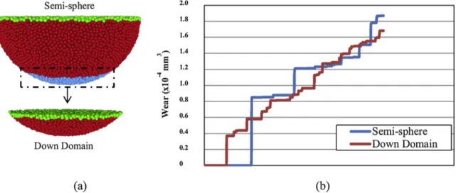
The computational cost of the wear model is too high, and thus the first issue is to minimize this cost. To this end, a comparison is made between the simulated semi-sphere and only the bottom zone of the abrasive grain. This verification is carried out for the WFA abrasive grain. The number of DEs is reduced from 41,671 to 5448 as shown in Fig. 9(a); therefore it appears that a reduction of approximately 85% is achieved by modeling only the bottom zone. Likewise, the micro density of the bottom zone has to be calculated in order to generate equivalent bodies. Moreover, the pressure applied to the WFA abrasive grain is 105 MPa, with the corresponding force applied on the Pressure Surface being different in both cases. This is due to the fact that the radius of the
Pressure Surface (R’) is different for semi-sphere and the bottom zone.
Table 5 displays the recalculated parameters, from which it can be observed that the normal force on the Pressure Surface is 7.42 N and 3.71 N respectively. Moreover, the micro friction coefficient, which reproduces the effect of sliding speed of 30 m/s in the model is μμ= 0.7.
Finally, the contact time of the wear simulation is 0.85 ms, as recorded for real tribological tests.
Fig. 9(b) plots the third body volume generation during the contact time. It appears that the increase in the third body is similar for the semi-sphere and the bottom zone. With regard to the trends shown in the graph, it can be concluded that both models show equivalent behavior. The value achieved for the third body is analyzed in the following section. Additionally, the reduction in the total computational time
supports the suggested approach of modeling the bottom zone.
5.2. Results for WFA abrasive grain wear model
Hereafter, only the bottom zone of the abrasive grain is modeled. Firstly, the wear behavior of the WFA abrasive grain is modeled. The model inputs are calculated in order to represent the real contact conditions between the abrasive grain and the workpiece. μμ= 0.7
re-produces 30 m/s sliding speed and the normal force equivalent to 105 MPa is 3.71 N, as shown inTable 5. The adhesion and micro-failure stress values are then adjusted in order to reproduce real wear behavior. High values of failure stress lead to no wear generation and low values tend to break the beams outside of the contact, as shown inFig. 10(a), in which 0.8 GPa is used. Therefore, it is established that the optimal value of micro failure stress is σfμ= 1 GPa for the WFA abrasive grain
under a set of given contact conditions. The final parameter to adjust is adhesion. If this corresponds to contact between two third body parti-cles or grainthird body partiparti-cles then this is set to γ = 0.001. If the contact between workpiece and third body is one order of magnitude lower, then γ = 0.0001. InFig. 10(b) and (c), the wear of the abrasive grain is shown in blue. The third body accumulates in the left part of the abrasive grain as opposed to the center of the grain due to the effect of the sliding speed.
With respect to the maximum stress of the beams, σfμ= 1 GPa (in
yellow inFig. 11) corresponds to break beams due to the failure criteria imposed. On the Pressure Surface both yellow and red colors (corre-sponding to 2.2 GPa) appear. However, these beams are defined as unbreakable and do not become wear. Likewise, third body evolution during a contact of 0.85 ms is shown inFig. 12. As highlighted, three different parts can be distinguished in the evolution of the wear. During the first 0.18 ms there is no wear, after which, up to approximately 0.38 ms the third body occurs but the increase is gradual. In the last step, the slope increases and the wear develops more rapidly, reaching a value of 2.18 × 10⁻⁴mm3for WFA. In comparison with the pin-ondisk
test, the height of the wear measured for the WFA is 23 μm,
Fig. 9. (a) Discretization of semi-sphere and only the bottom zone of the WFA abrasive grain and (b) Wear or Third body generation on the semi-sphere and only the
bottom zone.
Table 5
Micro properties and model inputs for semi-sphere and down domain.
ρμ[kg/m3] pr[MPa] R'[μm] F [N]
SEMI-SPHERE WFA 2.12 × 10¹² 105 150 7.42
BOTTOM ZONE WFA 1.62 × 10¹³ 105 106 3.71
corresponding to a discrete volume of 2.02 × 10⁻⁴mm3, with the error
being approximately 8%. Thus, the wear model is a good approach for reproducing the wear of the abrasive grain, and allows for gaining an understanding of the evolution of the wear during a complete contact.
5.3. Comparison between WFA and SG abrasive grains
Once the behavior of the WFA is reproduced, the wear of the SG alumina wear is modeled. The differences in the crystalline structure are considered in the thermal model when the heat flux is imposed on the abrasive grain, and thus in terms of the proportion of the domain affected by the temperature, for SG abrasive grains the bottom zone is slightly more affected by the temperature than WFA. Consequently, the
density of the DEs is recalculated, as shown inTable 5. The micro friction coefficient and adhesion adjusted for WFA are also valid for SG, and are thus independent of the crystalline structure of alumina. However, SG suffers less wear than WFA, and thus the failure stress of the beams must be higher than those of the WFA. In this case a mod-ification is needed in the failure criteria. As in the WFA wear model, the beams are broken if Von Mises stress is higher than the failure stress, as shown in Eq.(7). To achieve a wear behavior that is valid for both WFA and SG, a failure constant, C, is introduced in the failure criteria. This constant multiplies according to micro failure stress. For the case of WFA, C = 1 is considered. The best behavior of the SG abrasive grain is achieved for C=2.2, and thus the failure stress for SG abrasive grains is 2.2 GPa whilst for WFA this is 1 GPa.Fig. 11shows the differences in the maximum stress reached in both the WFA and SG abrasive grains. Furthermore, this figure shows the concentration of beams that reach the highest stress just at the moment of contact.
> C
vm fµ (7)
When comparing wear generation, SG appears to show a similar tendency, but there are three parts that can be distinguished in terms of wear evolution. In contrast, the wear generated on SG alumina is lower than that on WFA, as occurs on real tests. Moreover, SG abrasive grains suffer a wear of 17 μm in height on pin-on-disk tribometer tests, which corresponds to discrete volumetric wear of 1.23 × 10⁻⁴mm3, as shown
inFig. 12. For the numerical model the maximum wear achieved after 0.85 ms is 1.04 × 10⁻⁴mm3. Thus, the error between experimental and
numerical results is approximately 15%, which is higher than the WFA case. However, for both crystalline structures the error is not a handicap in the wear model, since this is one of the most relevant outcomes of this model for understanding the evolution of wear during a complete contact (whereas only the end of the contact can be studied in experi-mental tests).
6. Conclusions
The present study focused on examining the influence of both tri-bochemical reactions and third body generation on the evolution of wear in alumina grinding wheels whilst also taking into account the influence of the crystalline structure. This work follows previous ex-perimental studies of wear flat generation but attempts to address the limitations regarding the influence of temperature whilst monitoring the evolution of wear during a complete contact. On the basis of the results obtained, the following conclusions can be drawn:
•
With regard to temperature, two zones can be defined within the abrasive grain. The bottom zone behaves in the same way as ductile material, and acquires the properties of the alumina at the max-imum temperature reached in the contact. The SG abrasive grain reaches approximately 720 °C in the contact whilst the WFA reaches 600 °C at a sliding speed of 30 m/s.Fig. 10. (a) Incorrect micro failure stress (0.8 GPa) of the WFA abrasive grain, top view, and third body generation in the WFA abrasive grain with 1 GPa (b) down
view (c) front view.
Fig. 11. Beam stress of WFA and SG abrasive grains.
•
This work demonstrates the lower thermal conductivity of SG alu-mina. For WFA, the height of the isotherm — which separates thermal affected alumina from non-affected alumina — is approxi-mately 38 μm, and for SG, the abrasive grain is approxiapproxi-mately 47 μm. This height corresponds to 200 °C isotherm height.•
The wear of a single alumina abrasive grain has been modeled. The effect of wear flat of a tribochemical nature has been simulated due to the combination of a 2D finite element thermal model and 3D discrete element wear model using a cohesive beam model, which is able to reproduce the third body generation in continuous materials.•
Regarding the input parameters for the model, sliding speed is modeled as a micro tangential force on DEs in the contact. The micro friction coefficient at 30 m/s, which corresponds to the dy-namic friction coefficient, is μμ= 0.7. The pressure is imposed as anormal force that takes into account the mass of a complete system, that is, a complete real grinding wheel.
•
The wear of the abrasive grain was modeled using the adhesion γ = 0.001 and failure stress coefficient σfμ= 1 GPa. The Von Misesfailure criterion was imposed on the bottom zone of the abrasive grain and a failure constant was set in order to represent the influ-ence of the crystalline structure on the evolution of wear. For WFA, the failure constant is C = 1 and for SG this is C = 2.2. Thus, SG presents less wear than WFA.
•
This wear model shows the complete evolution of the third body generation in the contact between the abrasive grain and the workpiece. In contrast, on experimental tests only the final state of the alumina can be examined. The numerical simulation shows that the first wear appears at approximately 0.18 ms. for both WFA and SG abrasive grains, increasing slowly during the next 0.2 ms and presenting a higher rate of increase up to 0.85 ms. Likewise, the error achieved when comparing the experimental and numerical tests is around 8% for WFA and 15% for SG abrasive grains at the end of the contact.The present wear model was developed for WFA and SG crystalline structures under certain contact conditions. However, by varying μμand
the normal force, it is possible to simulate other contact conditions, and when adjusting γ and σfμ, other crystalline structures or grain-workpiece
contacts can be modeled. Following this work, the next step will be to simulate other types of wear, not only that of a tribochemical nature. Moreover, dynamic thermo-mechanical behavior of alumina abrasive grains can be simulated using GranOO. This complete model would replace the two models, the first one to simulate the temperature and the second one to simulate the wear.
Declaration of Competing Interest
The authors declare that they have no known competing financial interests or personal relationships that could have appeared to influ-ence the work reported in this paper.
The authors declare the following financial interests/personal re-lationships which may be considered as potential competing interests.
Acknowledgments
The authors gratefully acknowledge the funding support received from the Spanish Ministry of Economy and Competitiveness and European Regional Development Fund (ERDF) operation program for funding the project “Scientific models and machine-tool advanced sensing techniques for efficient machining of precision components of Low Pressure Turbines” (DPI2017-82239-P). Funding support was also received from the contracting call for the training of research staff in UPV/EHU, of Vice-rectorate of research, to develop this project.
References
Adibi, H., Rezaei, S.M., Sarhan, A.A.D., 2013. Analytical modeling of grinding wheel loading phenomena. Int. J. Adv. Manuf. Technol. 68, 473–485.https://doi.org/10. 1007/s00170-013-4745-z.
André, D., Charles, J.L., Iordanoff, I., Néauport, J., 2014. The GranOO workbench, a new tool for developing discrete element simulations, and its application to tribological problems. Adv. Eng. Softw. 74, 40–48.https://doi.org/10.1016/j.advengsoft.2014. 04.003.
André, D., Iordanoff, I., Charles, J.L., Néauport, J., 2012. Discrete element method to simulate continuous material by using the cohesive beam model. Comput. Methods Appl. Mech. Eng. 213–216, 113–125.https://doi.org/10.1016/j.cma.2011.12.002. Archard, J.F., 1953. Contact and rubbing of flat surfaces. J. Appl. Phys. 24, 981–988.
https://doi.org/10.1063/1.1721448.
Ardashev, D.V., 2015. Mathematic model of the blunting area of an abrasive grain in grinding processes, with account of different wear mechanisms. Procedia Eng. 129, 500–504.https://doi.org/10.1016/j.proeng.2015.12.049.
Aurich, J.C., Biermann, D., Blum, H., Brecher, C., Carstensen, C., Denkena, B., Klocke, F., Kröger, M., Steinmann, P., Weinert, K., 2009. Modelling and simulation of process: Machine interaction in grinding. Prod. Prod. Eng. 3, 111–120.https://doi.org/10. 1007/s11740-008-0137-x.
Badger, J.A., Torrance, A.A., 2000. Comparison of two models to predict grinding forces from wheel surface topography. Int. J. Mach. Tools Manuf. 40, 1099–1120.https:// doi.org/10.1016/S0890-6955(99)00116-9.
Blaineau, P., André, D., Laheurte, R., Darnis, P., Darbois, N., Cahuc, O., Neauport, J., 2015. Subsurface mechanical damage during bound abrasive grinding of fused silica glass. Appl. Surf. Sci. 353, 764–773.https://doi.org/10.1016/j.apsusc.2015.07.047. Brinksmeier, E., Aurich, J.C., Govekar, E., Heinzel, C., Hoffmeister, H.W., Klocke, F.,
Peters, J., Rentsch, R., Stephenson, D.J., Uhlmann, E., Weinert, K., Wittmann, M., 2006. Advances in modeling and simulation of grinding processes. CIRP Ann. -Manuf. Technol. 55, 667–696.https://doi.org/10.1016/j.cirp.2006.10.003. Chen, X., Rowe, W.B., 1996. Analysis and simulation of grinding process. Part I:
Generation of the grinding wheel surface. Int. J. Mach. Tools Manuf. 36, 871–882.
https://doi.org/10.1093/eurheartj/ehu271.
Cooper, W.L., Lavine, A.S., 2000. Grinding Process Size Effect and Kinematics Numerical Analysis. J. Manuf. Sci. Eng. 122, 59.https://doi.org/10.1115/1.538888. Fillot, N., Iordanoff, I., Berthier, Y., 2007. Modelling third body flows with a discrete
element method-a tool for understanding wear with adhesive particles. Tribol. Int. 40, 973–981.https://doi.org/10.1016/j.triboint.2006.02.056.
García, E., 2014. Improving Friction and Wear Conditions in Grinding. Practical Application and Fundamental Study. University of Basque Country.
Godino, L., Pombo, I., Sanchez, J.A., Alvarez, J., 2018a. On the development and evo-lution of wear flats in microcrystalline sintered alumina grinding wheels. J. Manuf. Process. 32.https://doi.org/10.1016/j.jmapro.2018.03.023.
Godino, L., Pombo, I., Sanchez, J.A., Izquierdo, B., 2018b. An original tribometer to analyze the behavior of. Metals (Basel) 8, 557.https://doi.org/10.3390/ met8070557.
Goupil, A., Iordanoff, I., Charles, J.L., Rinchet, A., 2013. Modelling of polishing tools for high spatial frequency defect correction on aspherical surfaces. Key Eng. Mater. 554–557, 1232–1241.https://doi.org/10.4028/www.scientific.net/KEM.554-557. 1232.
Hwang, T.W., Evans, C.J., Malkin, S., 2000. High speed grinding of silicon nitride with electroplated diamond wheels, part 2: wheel topography and grinding mechanisms. J. Manuf. Sci. Eng. 122, 42.https://doi.org/10.1115/1.538909.
Incropera, F., Dewitt, D., Bergman, T., Lavine, A., 2007. Fundamentals of Heat and Mass Transfer. John Wiley and Sons, United States of America, pp. 255–347.
Iordanoff, I., Berthier, Y., Descartes, S., Heshmat, H., 2002. A review of recent approaches for modeling solid third bodies. J. Tribol. 124, 725–735.https://doi.org/10.1115/1. 1467632.
Jiang, J.L., Ge, P.Q., Bi, W.B., Zhang, L., Wang, D.X., Zhang, Y., 2013. 2D/3D ground surface topography modeling considering dressing and wear effects in grinding process. Int. J. Mach. Tools Manuf. 74, 29–40.https://doi.org/10.1016/j. ijmachtools.2013.07.002.
Koshy, P., Jain, V.K., Lal, G.K., 1997. Stochastic simulation approach to modelling dia-mond wheel topography. Int. J. Mach. tools Manuf. 37, 751–761.https://doi.org/10. 1016/S0890-6955(96)00086-7.
Maheo, L., Dau, F., André, D., Charles, J.L., Iordanoff, I., 2015. A promising way to model cracks in composite using Discrete Element Method. Compos. Part B Eng. 71, 193–202.https://doi.org/10.1016/j.compositesb.2014.11.032.
Malkin, S., Guo, C., 2008. Grinding Technology. Theory and Applications of Machining With Abrasives.https://doi.org/10.1063/1.2717084.
Malkin, S., Cook, N.H., 1971. The wear of grinding wheels. Part 1: Attritious wear. J. Eng. Ind. 93 (4), 1120–1128.
Mayer, J., Engelhorn, R., Bot, R., Weirich, T., Herwartz, C., Klocke, F., 2006. Wear characteristics of second-phase-reinforced sol-gel corundum abrasives. Acta Mater. 54, 3605–3615.https://doi.org/10.1016/j.actamat.2006.03.049.
Nadolny, K., 2014. State of the art in production, properties and applications of the mi-crocrystalline sintered corundum abrasive grains. Int. J. Adv. Manuf. Technol. 74, 1445–1457.https://doi.org/10.1007/s00170-014-6090-2.
Nadolny, K., 2015. Wear phenomena of grinding wheels with sol–gel alumina abrasive grains and glass–ceramic vitrified bond during internal cylindrical traverse grinding of 100Cr6 steel. Int. J. Adv. Manuf. Technol. 77, 83–98.https://doi.org/10.1007/ s00170-014-6432-0.
Osa, J.L., Sánchez, J.A., Ortega, N., Iordanoff, I., Charles, J.L., 2016. Discrete-element modelling of the grinding contact length combining the wheel-body structure and the
surface-topography models. Int. J. Mach. Tools Manuf. 110, 43–54.https://doi.org/ 10.1016/j.ijmachtools.2016.07.004.
Rasim, M., Mattfeld, P., Klocke, F., 2015. Analysis of the grain shape influence on the chip formation in grinding. J. Mater. Process Technol. 226, 60–68.https://doi.org/10. 1016/j.jmatprotec.2015.06.041.
Xi, X., Yu, T., Ding, W., Xu, J., 2018. Grinding of Ti 2 AlNb intermetallics using silicon carbide and alumina abrasive wheels : tool surface topology e ff ect on grinding force and ground surface quality. Precis. Eng. 53, 134–145.https://doi.org/10.1016/j. precisioneng.2018.03.007.
Yu, T., Bastawros, A.F., Chandra, A., 2017. Experimental and modeling characterization of wear and life expectancy of electroplated CBN grinding wheels. Int. J. Mach. Tools Manuf. 121, 70–80.https://doi.org/10.1016/j.ijmachtools.2017.04.013. Zhao, B., Ding, W., Chen, Z., Yang, C., 2019. Pore structure design and grinding
perfor-mance of porous metal-bonded CBN abrasive wheels fabricated by vacuum sintering. J. Manuf. Process. 44, 125–132.https://doi.org/10.1016/j.jmapro.2019.06.001. Zhu, Y., Ding, W., Rao, Z., Yang, C., 2019. Micro-fracture mechanism of polycrystalline
CBN grain during single grain scratching tests based on fractal dimension analysis. Precis. Eng. 59, 26–36.https://doi.org/10.1016/j.precisioneng.2019.05.010.