HAL Id: hal-01468586
https://hal.archives-ouvertes.fr/hal-01468586
Submitted on 15 Feb 2017
HAL is a multi-disciplinary open access
archive for the deposit and dissemination of
sci-entific research documents, whether they are
pub-lished or not. The documents may come from
teaching and research institutions in France or
abroad, or from public or private research centers.
L’archive ouverte pluridisciplinaire HAL, est
destinée au dépôt et à la diffusion de documents
scientifiques de niveau recherche, publiés ou non,
émanant des établissements d’enseignement et de
recherche français ou étrangers, des laboratoires
publics ou privés.
A Multiview Framework Driven by Use Cases to
Support the Design of Service Components
Emmanuel Renaux, Gilles Vanwormhoudt, Christophe Tombelle
To cite this version:
Emmanuel Renaux, Gilles Vanwormhoudt, Christophe Tombelle. A Multiview Framework Driven by
Use Cases to Support the Design of Service Components. 2013 IEEE Seventh International Symposium
on Service-Oriented System Engineering, Mar 2013, San Francisco, United States. pp.268 - 273,
�10.1109/SOSE.2013.47�. �hal-01468586�
A Multiview Framework Driven by Use Cases
to Support the Design of Service Components
Emmanuel Renaux
1, Gilles Vanwormhoudt
1,2and Christophe Tombelle
11
TELECOM Lille 1 / Institut MINES-TELECOM
2LIFL / CNRS - University of Lille 1 (UMR 8022)
59655 Villeneuve d’Ascq cedex - France
{renaux, vanwormhoudt, tombelle}@telecom-lille1.eu
Abstract—In the field of software technologies, the adoption of Service Oriented Architecture for IS has been accompanied by the introduction of new service component models which are well-suited to realize services. While these service compo-nents offer new capabilities to simplify the construction and maintenance of IS, the issue of their design needs to be further examined as current existing works do not sufficiently bridge the gap between requirements and service component models. In this paper, we present a multi-view framework to support the design of services along the development process. The framework is grounded on the notion of Logical Service Block which represents a service from Use case to assembly model and acts as a pivot between views ensuring the consistency and the traceability of services at different stages and levels of detail. The proposed framework has been implemented to provide a UML2 tool that helps designers in elaborating views and projecting services towards a specific platform like SCA.
Keywords-service component, service design, use case, view, UML, traceability, engineering process.
I. INTRODUCTION
Information systems (IS) have been the battlefield of successive campaigns of re-engineering for new features and new technologies. Recently, the technology change was the Service Oriented Architecture (SOA) [1]. This architec-ture framework has been adopted to partition IS in coarse grained, loosely coupled and autonomous services which encompass one or more business or technical discrete func-tions. SOA adoption has led to propose new approaches and new software artifacts for their design and implementation. The introduction of several service component models [2], [3], like SCA, OSGI and Fractal is one of these novelties. The services are then provided by service components which may in turn use services provided by other components and be assembled into composites to provide specific business capabilities. While service component models promise sev-eral benefits in terms of evolution and maintenance, the design of complex IS based on such components remains an important issue. In particular, questions about how to identify such service components, how to elaborate their external and internal structure and how to put them in a consistent assembly still need to be investigated.
Existing works only offer partial responses. On one side,
some works provide top-down solutions to identify services from the requirements by using an approach driven either by business process either by use cases [5], [6]. It appears however that most of these works do not consider the rest of the development process. The SOAML specification recently adopted by OMG [7] fills the gap but its notion of service is transverse to components and therefore is not well align with current service component models. On the other side, some works enable the modeling of service components during the design phase, mainly in the scope of the UML notation. According to these works, this modeling is achieved either by reusing existing constructs and diagrams [8] either by extending UML with appropriate profiles [9]. Unfortunately, we observe that the modeling of service components pro-moted by these works is generally not related with the requirements about services. In addition, service components are often considered as technological concerns.
In this paper, we propose a multi-view framework driven by use cases to support the design of service components from requirements to implementation. The novelty of this ap-proach compared to existing works is explained in Section II. In the framework, each view addresses a specific concern of the design process and models parts of the services or their assembly (see Section III). The framework is based on the notion of Logical Service Block which represents a service from requirements to design and acts as a pivot between views ensuring their consistency and enabling round-trip derivations. This pivot supports the traceability of services at different levels of detail and consequently improves the quality and readability of system models. The framework has been implemented to provide a UML2 tool (see Section IV) that helps designers during the elaboration of views and the projection of services toward a specific platform like SCA.
II. USE CASE ANDSERVICES
Despite intensive SOA adoption in recent years, no unified methodological approach to identify and design services from business requirements [1] has been reached yet. In-stead, top-down and bottom-up approaches have been pro-posed. In this paper, we are interested in top-down ones, that can be further divided into those driven by the business
process and those driven by use cases. A lot of top-down approaches [5], [7], [10] follow the process-driven method either by formulating guidelines to identify services or by deducting services from process models in a systematic manner. However, process-driven approaches also commonly bear some difficulties: need of a complete knowledge of the enterprise processes, too much process-oriented and too large scope for small and medium-sized systems.
Compared to process-driven approaches, the main ar-guments in favor of use-case driven ones are: first, use cases offer a systematic and intuitive means to capture functional requirements with a focus on the value added for the user, secondly, they can drive the whole development process. Regarding the relationship between use cases and services, we have found works with different focus. A first group has explored use cases as a way to characterize and integrate existing software services in relation with business requirements [11], [12]. A second group of works, which is more specifically related to our proposal, addresses the issue of constructing new service-based systems from use cases capturing requirements. We review these works hereafter.
Authors of [13] propose a description of services based on several related use cases derived from parts of the Use Case diagram: scripts like participants, system or extensions paths. To complete this description, a process and guidelines to direct the analysis are given. The work described in [6] also proposes to derive the structure of services from the Use Case diagram. For that purpose, each use case is assumed to map a service-oriented artifact and associations between primary actors and use-cases serve to identify interfaces of such services. In [14], the mapping of use cases to services is also considered. Business and technical criteria to decide how to group use cases relatively to a particular business service component are given to drive this mapping process. [15] also discusses use case as a requirements acquisition method which is applied to SOA requirements. The authors mainly explain how to exploit use case as a supplement to the model of business processes but they do not provide a guideline to identify the relevant services. More recently, [16] makes an extensive usage of use cases to produce service inventories from business requirements. In this work, each business service is itself modeled as a collection of candidate services represented by use cases marked with stereotype for services types and aggregated with inclusion relationship. In addition, service repositories are related to participants in a clustered Use Case diagram.
To sum up the reviewed works, few ones make the association between use cases and services by just providing guidelines while others aim to offer an explicit representa-tion of services within the Use Case diagram. For the latter category, we have found works that just rely on a particular arrangement or interpretation of existing use case constructs. Some other works extend use case with new concepts and relationships using the profile mechanism. Although these
works provide a useful basis to relate use cases and services, they mainly focus on the Use Case diagram but not on all other steps of the development process. Exceptions are [6], [14] but in these works, the issue of designing service components is only treated superficially and no support is provided to maintain the consistency of designed services from requirements to implementation. In the next section, we propose a multi-view framework in response to this problem.
III. OURMULTI-VIEW FRAMEWORK FOR MODELING
SERVICE-BASEDIS A. Overview
In our framework, the notion of Logical Service Block (LSB) is the main piece of design process of a system. This unit of modeling represents the service from requirements to design and groups elements related to a same service. Thanks to this notion, we facilitate the traceability of ser-vices at each stage and support a decomposition of the system that enables to partition and reduces the design effort.
Iterative Process Assembly View «logicalServiceBlock» DeskManagement Book a room Register arriving guest Check out guest Booking Checking «delegate» «delegate» «delegate» Customer guest guest HotelRoom bookedRoom occupedRoom Payment «delegate» Assign a room assignedRoom Compute bill occupant guest «delegate» room «logicalServiceBlock» DeskManagement Book a room Register arriving guest Check out guest Booking Checking «delegate» «delegate» «delegate» Customer guest guest HotelRoom bookedRoom occupedRoom Payment «delegate» Assign a room assignedRoom Compute bill occupant guest «delegate» room «logicalServiceBlock» DeskManagement Booking Checking «control» CheckOutGuest Payment occupedRoom guest «delegate» «control» ComputeBill «entity» Customer «entity» HotelRoom «delegate» «delegate» room «control» BookARoom «control» RegisterArrivingGuest «control» AssignARoom «delegate» guest bookedRoom «delegate» guest occupant assignedRoom «logicalServiceBlock» DeskManagement Booking Checking «control» CheckOutGuest Payment occupedRoom guest «delegate» «control» ComputeBill «entity» Customer «entity» HotelRoom «delegate» «delegate» room «control» BookARoom «control» RegisterArrivingGuest «control» AssignARoom «delegate» guest bookedRoom «delegate» guest occupant assignedRoom «logicalServiceBlock» DeskManagement Booking Checking Payment «logicalServiceBlock» Accountancy SetRoomRates «logicalServiceBlock» Accountancy «logicalServiceBlock» DeskManagement Guest DeskClerk Book a room Register arriving guest Check out guest Collect guest's payment «externalUse»
Set room rates HotelManager
«include»Assign room Compute bill «include»
:CheckOutForm guest:
Customer :CheckOutGuest :DeskClerc occupedRoom:HotelRoom:Payment
identify guest identifyGuest() getGuestData() check room checkRoom() getStayDetails() printBill() show bill() process payment processPayment() processPayment() getRoomRate() :ComputeBill computeBill() :CheckOutForm guest: Customer :CheckOutGuest :DeskClerc occupedRoom: HotelRoom :Payment identify guest identifyGuest() getGuestData() check room checkRoom() getStayDetails() printBill() show bill() process payment processPayment() processPayment() getRoomRate() :ComputeBill computeBill()
:CheckOutForm:CheckOutGuest Customerguest:
:DeskClerc occupedRoom:
HotelRoom :Payment
identify guestidentifyGuest() getGuestData() check roomcheckRoom()
getStayDetails() printBill() show bill() process payment processPayment() processPayment() getRoomRate() :ComputeBill computeBill() Service scope Service scope Collaboration scope System scope System scope
Use Case View
Interaction View
Service Design View Collaboration Analysis View
Deductive derivation
Payment
View
Process step
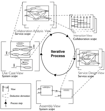
Figure 1. Overview of the iterative process and its 3 scopes
In addition to the notion of LSB, our framework provides several views to describe a system. Each view addresses a specific concern related to a particular LSB or an assembly of LSBs. The notion of LSB is omnipresent but each view has a unique way to represent it with different constituents depending on the view. As the semantics is the same in each view, an LSB acts as a pivot that links the content of each views. This pivot is a support for traceability of services
at different levels of detail and consequently improves the quality and readability of system models.
Figure 1 gives an overview of our framework and its underlying iterative process. In this process, each step corresponds to a view. A specific view can be elaborated iteratively, while remaining consistent with other views. For instance, a designer can draft the Use Case view, then proceed with the Collaboration Analysis view to refine the LSBs. By getting them into details, new requirements may be identified that cause the designer to revise the contents of the corresponding LSB within the Use Case view.
In the following, we explain each view in more detail and illustrate them with a management system for hotel rooms. B. Detail of views and illustrations
1) Use Case view: The Use Case view (UCv) concerns
the requirements and is founded on the UML use case diagram with adding of the LSB notion and externalUse relationship. A UCv allows to decompose a system in LSBs, by grouping use cases related to the same service. For our example (see figure 2), we obtain two LSBs, one for reservation and occupation of the room and one for accountancy concerns. As we can see, each LSB contains the subset of the use cases related with the service it contributes to. These use cases will be realized by elements enclosed within the LSB in other views of the system.
«logicalServiceBlock» Accountancy «logicalServiceBlock» DeskManagement Guest DeskClerk Book a room Register arriving guest Check out guest Collect guest's payment «externalUse»
Set room rates HotelManager
«include»
Assign room Compute bill
«include»
Figure 2. Use case view of the Hotel Management System
Standard relationships between use cases, extend and include, are kept but their use is limited to the inside of an LSB. To cross LSB boundaries, we add the non-standard
externalUse relationship which explicitly shows the
func-tional dependencies between service use cases. Relations that cross boundaries, either between actors and services, either between services, will be captured into interfaces between services in other views. In Figure 2, the externalUse relation between the two LSBs, expresses the interactions between the use cases of these services. Designers are free to choose the best decomposition, the one that reduces interactions and dependencies through boundaries, or simply the one that takes into account IS constraints. UML activity diagrams, modeling business process flows, can help in grouping use cases. As we will see after, this decomposition is maintained in subsequent views to make the corresponding model simpler to understand, change, and maintain.
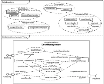
2) Collaboration Analysis view: The Collaboration
Anal-ysis view (CAv) describes the realization of identified use cases in terms of collaborations and objects. Like in UML, a collaboration defines a set of roles played by objects. This concept precises how a use case is realized. To enhance the traceability, collaborations are grouped like use cases following the LSB they describe.
In figure 3, we can see that each use case contained in an LSB is transformed into a set of one or several
collaborationswhich define the roles played by the objects
to realize the use case. These roles are attached to participat-ing objects through collaboration bindparticipat-ings. This way, each participation of an object in a collaboration is represented by a link characterizing its role in this interaction. For instance, a customer object is enrolled in the CheckOutGuest collaboration and has a guest role within it. Roles played by an object will determine its interfaces in the design view.
Ports appear in this view to hold required and provided
interfacesto implement dependencies detected in the UCv.
Here, the Booking provided interface realizes the relationship between Guest actor and Book a room use case. These interfaces allow actors to request services and services to be connected. «logicalServiceBlock» DeskManagement : BookARoom : RegisterArrivingGuest : CheckOutGuest Booking Checking guestGui deskClerkGui deskClerkGui customer : <Undefined> guestHandler guestHandler room: HotelRoomManager bookedRoomHandler occupedRoomHandler Payment payment : AssignARoom assignedRoomHandler occupant guestHandler
Collaboration Analysis View
BookARoom gestGui guestHandler bookedRoomHandler AssignARoom occupantHandler assignedRoomHandler CheckOutGuest deskClekGui guestHandler payment : ComputeBill payment roomHandler roomToPay Collaborations roomToPay payment ComputeBill ...
Figure 3. Collaboration Analysis View of the DeskManagement Service
An object can play a role in several collaborations speci-fied for an LSB but it does not inevitably play the same role. However, as one goal is to minimize dependencies between services, we do not authorize the enrollment of an object in collaborations within another LSB. If needed, it is possible to add required interfaces to define connections between ser-vices as actors interactions. For instance, Payment required interface comes from externalUse relation of the UCv.
3) Interaction view (Iv): The Interaction view (Iv)
par-tially models the collaborations identified for an LSB in the CAv. This view represents message exchanges between the
roles of a collaboration during the execution of a use case scenario. In addition, to give more details about a particular collaboration, this view is also intended to prepare the design of a service within the Service Design view. Furthermore, this view can help to discover LSBs and to establish their boundaries iteratively with the other views.
We use UML-like sequence diagrams to represent the interactions of a collaboration in terms of roles but we introduce some new specific role types to better characterize the kind of behavior attached to a role and render the interactions of an LSB with external services and actors. The Control role manages all the steps described in the scenario. The Entity role is a kind of business object easily identified in specifications. It contains the information of the system as well as the business processes. Boundary roles are ones played by the service to respond to actors. Finally, the
External Control rolerepresents required functions provided
by another system or service. Boundary and External
Con-trol rolescan be considered respective representations of the
provided and required ports.
:CheckOutForm guestHandler:
CustomerManager
:CheckOutGuest
:DeskClerk occupedRoomHandler:
HotelRoomManager :Paymentpayment
identify guest identifyGuest() getGuestData(id) check room checkRoom() getStayDetails(id) show bill() process payment processPayment() processPayment() computeBill() printBill() :ComputeBill getRoomRate()
Actor Entity role Control role Boundary role External Control role
Figure 4. An interaction View of the Checkout Guest Collaboration
Figure 4 shows one Iv for the Checkout collaboration pre-sented previously. The CheckOutForm boundary role models the interactions between the service and its environment. The latter role exchanges messages with the CheckoutGuest Control role. Other roles are Entity roles (e.g. HotelRoom-Manager). The Payment External Control role involved in the payment phase captures the use of a Control role from another service. The message receives by the Control role through boundary roles and the messages sent through External Control roles serve to define respectively provided and required interfaces of a service.
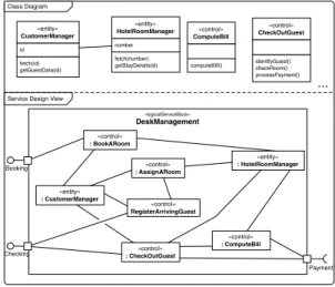
4) Service design view: The Service Design view (SDv)
describes the software elements, their structure and the relationships supporting the behavior of an LSB described in its Interaction views. In this view, an LSB provides interfaces that expose its business methods and organize them according to the points of view of the client service.
The control and the entity parts contain respectively the business processing and information management. The
con-trol partsencapsulate processing due to use case scenarios
and manage all its steps. It plays the intermediate role between ports and entity parts. The entity parts manage the business objects, containing facility to access data as well as the business processes.
Service Design View
«logicalServiceBlock»
DeskManagement
Booking
Checking : CheckOutGuest«control»
Payment «entity» : CustomerManager «entity» : HotelRoomManager «control» : BookARoom «control» RegisterArrivingGuest «control» : AssignARoom fetch(id) getGuestData(id) id «entity» CustomerManager fetch(number) getStayDetails(id) number «entity» HotelRoomManager identifyGuest() checkRoom() processPayment() «control» CheckOutGuest Class Diagram «control» : ComputeBill computeBill() «control» ComputeBill ...
Figure 5. Service Design View of the DeskManagement service
In the example, the DeskManagement LSB service has provided interfaces corresponding to control roles described in the Iv (e.g. CheckoutGuest, figure 5). Provided interfaces are implemented by one or several parts. Entity roles are good candidates to become Entity Parts of a service as the HotelRoomManager. Some parts, such as ComputeBill, need data or processing from another service. To do that, they delegate to required ports like Payment.
5) Assembly View (Av): As shown by Figure 6, the
Assembly view (Av) has the same scope as the UCv, i.e. the representation of the whole system in terms of LSBs, but gives a black box view of services and focuses on their connections. Each logical service is only represented with its ports and these ports are connected to ports of other services when it needs their operations. A connector always links a port specifying a required interface to a port specifying a provided interface of distinct LSBs. The connections between LSBs are the realization in the design view of their related externalUse relations in the UCv.
«logicalServiceBlock» DeskManagement Booking Checking Payment «logicalServiceBlock» Accountancy SetRoomRates
Figure 6. Assembly view of the Hotel Room Management system
Given this last view and all the previous ones, we reach a complete model of the system with consolidated LSBs. This
View Stereotype Target metaclasses System «System» Package UCv «UseCaseView» Package UCv «LogicalServiceBlock» Package UCv «externalUse» Relationship CAv «CollaborationView» Package CAv «LogicalServiceBlock» Component CAv «Required» Port CAv «Provided» Port
CAv «LogicalServicePart» CollaborationUse Iv «ControlRole» LifeLine Iv «EntityRole» LifeLine Iv «BoundaryRole» LifeLine Iv «ExternalRole» LifeLine SDv «LogicalServiceBlock» Component SDv «ControlPart» Property SDv «EntityPart» Property SDv «delegate» Relationship Av «AssemblyView» Package Av «LogicalServiceBlock» Component Table I
STEREOTYPES DEFINED FOR THE PROFILE
modeling is completely independent of any technological aspects and follows the classical Model Driven Architecture approach, it is then possible to translate these services into artifacts corresponding to a technological platform like SCA as explained in the following section.
IV. TOOLING
To experiment and validate our framework, we have de-veloped a modeling tool integrated into Eclipse environment. This tool provides a set of functions to help the designer with the creation of views, the maintenance of the consistency of the complete model and its projection to specific platforms. A. Metamodeling
Most of the concepts in our framework are close to UML2 ones. As a result, we have implemented them in the form of a profile for the UML modeling tools included with the Eclipse environment. Table I gives the set of stereotypes and metaclasses targeted, used to represent these concepts and each separate view. The capacity of a stereotype to be applied to distinct UML concepts is exploited to render the same concept in distinct views (see Component and Package for example). Inversely, we also use the capacity to apply distinct stereotypes to a same concept in order to render views of a system with separate packages.
B. View Consistency
We have defined OCL constraints to guarantee the con-sistency of views. These constraints are classified in two categories: 1) Intra-view constraints check the correct appli-cation of the proposed stereotypes on UML2 elements and check properties on the structure of stereotyped elements within a view; 2) Inter-views constraints concern with the consistency between views. They check properties between elements of a view with those included in other views. Here-after, we give some OCL constraints defined for our profile
in each category. Inter-views constraints are expressed in the context of the «System» root package to simplify the comparison of elements from multiple views.
/ / Query t o t e s t i f an e l e m e n t h a s a s t e r e o t y p e c o n t e x t E l e m e n t d e f : h a s S t e r e o t y p e ( s t e r e o t y p e : S t r i n g ) : B o o l e a n = s e l f . g e t A p p l i e d S t e r e o t y p e s ( )−>one ( s : S t e r e o t y p e | s . name = s t e r e o t y p e ) ) / / I n t r a−v i e w C o n s t r a i n t : A l l << e x t e r n a l U s e >> r e l a t i o n s h i p s m u s t l i n k U s e C a s e s f r o m << L o g i c a l S e r v i c e B l o c k >>. c o n t e x t D e p e n d a n c y i n v : s e l f . h a s S t e r e o t y p e ( ’ e x t e r n a l U s e ’ ) i m p l i e s ( s e l f . s o u r c e . owner . h a s S t e r e o t y p e ( ’ L o g i c a l S e r v i c e B l o c k ’ ) and ( s e l f . t a r g e t . owner . h a s S t e r e o t y p e ( ’ L o g i c a l S e r v i c e B l o c k ’ ) )
/ / I n t r a−v i e w C o n s t r a i n t : S o u r c e and t a r g e t UseCase o f a l l << e x t e r n a l U s e >> r e l a t i o n s h i p s m u s t n o t b e l o n g t o t h e same LSB . c o n t e x t D e p e n d a n c y i n v : s e l f . h a s S t e r e o t y p e ( ’ e x t e r n a l U s e ’ ) i m p l i e s ( s e l f . s o u r c e . owner <> s e l f . t a r g e t . owner ) / / I n t e r−v i e w s C o n s t r a i n t : R e q u i r e d P o r t o f a LSB i n t h e CAv m u s t match << e x t e r n a l U s e >> r e l a t i o n s h i p i n t h e u s e c a s e UCVview c o n t e x t P a c k a g e i n v : s e l f . h a s S t e r e o t y p e ( ’ S y s t e m ’ ) i m p l i e s l e t u s e c a s e v i e w = s e l f . n e s t e d P a c k a g e −>s e l e c t ( p : P a c k a g e | p . h a s S t e r e o t y p e ( ’ UseCaseView ’ ) ) i n l e t u s e c a s e L S B = u s e c a s e v i e w . a l l O w n e d E l e m e n t s ( )−> s e l e c t ( e : E l e m e n t | e . h a s S t e r e o t y p e ( ’ L o g i c a l S e r v i c e B l o c k ’ ) ) i n l e t c o l l a b v i e w = s e l f . n e s t e d P a c k a g e −>s e l e c t ( p : P a c k a g e | p . h a s S t e r e o t y p e ( ’ C o l l a b o r a t i o n V i e w ’ ) i n l e t c o l l a b L S B = d e s i g n v i e w . a l l O w n e d E l e m e n t s ( )−> s e l e c t ( e : E l e m e n t | e . h a s S t e r e o t y p e ( ’ L o g i c a l S e r v i c e B l o c k ’ ) ) i n
c o l l a b L S B −>f o r A l l ( c : Component | u s e c a s e L S B−>e x i s t s ( p : P a c k a g e | c . name = p . name and
p−>s e l e c t ( e : E l e m e n t | e . h a s S t e r e o t y p e ( ’ e x t e r n a l U s e ’ ) ) . s i z e ( ) = c . o w n e d P o r t −>( p o r t : P o r t | p o r t . h a s S t e r e o t y p e ( ’ R e q u i r e d ’ ) ) . s i z e ( ) )
All the OCL constraints have been implemented using the OCL engine included in the Eclipse environment. They can be checked at any time during the design to test the model consistency and its conformity with our abstract model. C. View derivation Guest DeskClerk Book a room Register arriving guest Check out guest Collect guest's payment «externalUse»
Set room rates
HotelManager
«include» Assign room
Compute bill «include» «logicalServiceBlock» DeskManagement Book a room Register arriving guest Check out guest Guest ProvidedPort DeskClerk ProvidedPort «delegate» «delegate» «delegate» Accountancy Service «delegate» Assign a room Compute bill «delegate» Guest RequirecPort View Derivation (UseCaseView to CollaborationView) DeskManagement «logicalServiceBlock» Accountancy«logicalServiceBlock» (UML2 Package) (UML2 Component)
Figure 7. Example of view derivation
As explained in section III-A, the dependencies between the contents of some views and the contents of other ones ensure traceability along the design. To facilitate the creation of a view from another one, we provide a set of model transformations (see deductive derivations in Figure 1). Each transformation takes a profiled model containing the input view and completes the model by adding the target view. The
input view must include all the elements required to produce the output view. The result is not intended to be complete and must be considered as a first sketch to be refined and improved. In Figure 7, we can observe that the derived view lacks some elements included in the CAv of figure 3 like role bindings or parts for instance. These elements cannot be deduced from the input view. The designer will generally add them afterwards. All the provided transformations have been written using the QVT language.
D. Projection to the Service Component Architecture The objective of our modeling framework is to obtain a system specification which is independent of technological concerns. In order to target a specific platform of services, a transformation of models. In our modeling tool, we propose a QVT transformation that enables the construction of a Service Component Architecture (SCA) model from a model based upon our profile. The provided transformation uses the profiled UML2 as the source metamodel and the SCA metamodel as target one. For this transformation, only the SDv of each LSBs and the Av of a profiled UML2 model are considered to produce the resulting SCA model. In the resulting model, nor bindings of services and references nor SCA components implementations are specified in order to let the designers choose the best technical platform to implement their services (JAVA, EJB, WSDL, ...).
V. CONCLUSION
In this paper, we propose a multi-view framework to deal with service boundaries very early in the development process and to better ensure their traceability. The proposed framework has been experimented in actual projects from large business domains, i.e. insurance, banking, health care. Two case studies experimenting the framework are described in [17], [18], one to design an E-Learning system and one to refund parts of IS of French waterways. All along these experiments, it has been felt that applying services division early in the process and that maintaining consistency with a tool is more efficient. Furthermore, the framework has also enabled and accelerated human interactions, making all stakeholders participating in the service identification of their IS. Finally, traceability has been maintained more easily and the impact of an evolution is more quickly detected.
A first perspective aims to synchronize views in our modeling tools. Currently, views are not updated to reflect the changes in others. To avoid consistency problems, we want to propose a solution that automatically propagates the changes in dependent views or, if not possible, provides the designer with suggestions to make the update manually. In the scope of this paper, we have mainly focused on functional requirements which are generally the first and main focus of interest during services design. We acknowl-edge that non-functional requirements are also an issue of SOA [4] and we are currently studying policies (security,
transaction) of service component model to address this dimension in the scope of our approach. Finally, the last perspective concerns the reusability of services modeled with our approach, particularly with regard to their view-based structuring. This perspective will be investigated with the goal to make reusable LSBs a key accelerator for the design of service-oriented systems.
REFERENCES
[1] M. Bell, Service-Oriented Modeling: Service Analysis, De-sign, and Architecture. Wiley&Sons, 2008.
[2] A. Karmarkar and M. Edwards. Assembly of business systems using service component architecture. In Proc. of Service-Oriented Computing ICSOC 2006, LNCS, Springer, 2006. [3] B.J. Kramer, Component meets service: what does the
mon-grel look like?, Journal of Innovations in Systems and Soft-ware Engineering, Springer, 2008.
[4] H. Becha and D. Amyot. Nonfunctional Properties in SOA -a Consumer’s Perspective. Journ-al of Softw-are, 2012. [5] A. Arsanjani et al., SOMA: A method for developing
service-oriented solutions, IBM System Journal, vol. 47, 2008. [6] L. Bocchi, J.L. Fiadeiro, and A. Lopes. A use-case driven
approach to formal service-oriented modelling. In Proc. of Symp. on Leveraging Applications of Formal Methods, Ver-ification and Validation, Springer, 2008.
[7] B. Elvesoeter et al., Model-driven service engineering with SOAML. In book Service Engineering, Springer, 2011. [8] P. Weiss, J. Zendulka, Modeling of Services and Service
Collaboration in UML 2.0. In Proc. of Information Systems and Formal Models, 2007.
[9] V. Ermagan, I.H. Kruger, A UML2 Profile for Service Mod-eling. In Proc. of MDE Languages and Systems, 2007. [10] L.G. Azevedo et al., A Method for Service Identification
from Business Process Models in a SOA Approach. In Proc. of 10th Int. Workshop on Enterprise, Business-Process and Information Systems Modeling, 2009.
[11] B. Zhao, G. Cai, Z. Jin, From Use Case Model to Service Model: An Environment Ontology Based Approach, In Proc. of Conference on Grid and Cooperative Computing, 2010. [12] V. Alkkiomaki, K. Smolander, Integration Use Cases - An
Applied UML Technique for Modeling Functional Require-ments in SOA. In Proc. of the Conference on RequireRequire-ments Engineering: Foundation for Software Quality, 2007. [13] S. Huayou et al., A Service-Oriented Analysis and Modeling
Using Use Case Approach. In Proc. of Computational Intel-ligence and Software Engineering, 2009.
[14] PZ. Stojanovic, A. Dahanayake, and H. Sol. Modeling and design of SOA. In Proc. of Int. Conference on Systems, Man and Cybernetics, IEEE, 2004.
[15] E. Knauss and D. Lubke. Using the Friction between Business Processes and Use Cases in SOA requirements. In Proc. of Conference on Computer Software and Applications, 2008. [16] P. Lago and M. Razavian. A Pragmatic Approach for Analysis
and Design of Service Inventories. In Proc. of Service-Oriented Computing - ICSOC Workshops, Springer, 2011. [17] E. Renaux, Component based approach to design Information
System, Phd Thesis from the University of Lille, 2004. [18] E. Renaux, P.A. Caron, X. Le Pallec, Learning Management
System component-based design: a model driven approach, In Proc. of Montreal Conference on eTechnologies, 2005.