HAL Id: hal-01149875
https://hal.sorbonne-universite.fr/hal-01149875
Submitted on 3 Sep 2019
HAL is a multi-disciplinary open access
archive for the deposit and dissemination of
sci-entific research documents, whether they are
pub-lished or not. The documents may come from
teaching and research institutions in France or
abroad, or from public or private research centers.
L’archive ouverte pluridisciplinaire HAL, est
destinée au dépôt et à la diffusion de documents
scientifiques de niveau recherche, publiés ou non,
émanant des établissements d’enseignement et de
recherche français ou étrangers, des laboratoires
publics ou privés.
Wideband Diamond Dipole Antenna with Broadside
Radiation Characteristics
Chetan Joshi, Julien Sarrazin, Anne-Claire Lepage, Xavier Begaud
To cite this version:
Chetan Joshi, Julien Sarrazin, Anne-Claire Lepage, Xavier Begaud. Wideband Diamond Dipole
An-tenna with Broadside Radiation Characteristics. Conference EuCAP 2015, Apr 2015, Lisbonne,
Por-tugal. �hal-01149875�
Wideband Diamo
Rad
Chetan Joshi
1, Ju
1 Institut Mines Teleco 2 Sorbonne Universi
Abstract—This paper presents a low diamond dipole antenna backed with an A Conductor. The paper addresses the proble broadside gain due to the split in the radiati particular frequencies within the operati solution is proposed by using a hybrid A Conductor that can effectively cancel this ef antenna is characterized by an overall thickne corresponds to a tenth of wavelength at th frequency.
Index Terms—Wideband diamond dipole Magnetic Conductor, directive antenna.
I. INTRODUCTION
A printed diamond dipole is an interestin of its wide operating bandwidth. When coup plane, the gain of the antenna is mainly broadside direction. The problem with class made of electrical conductors like copper is be placed at a distance of a quarter wave promote constructive interference in the broa magnetic conductor is a solution to this p does not cause a phase reversal of the inci thereby allowing the antenna to be placed ground plane. An Artificial Magnetic Cond been traditionally designed using the Sieven printed surfaces [1]. The dipoles in proxim been previously studied in various works. In pattern splits close to the resonant frequency is corrected by changing the periodicity of t it is observed that radiation pattern splits in in the bandwidth. For applications that requ broadside direction of the antenna, appear split radiation pattern inhibit the functioni This paper presents a UWB antenna desig tackles the problem of splitting of radiation hybrid AMC.
II. DESIGN
The antenna structure comprises of th backed with an artificial magnetic conduct printed on CuClad Substrate of thicknes dielectric constant, εr = 2.5 and loss tangen
The dimensions of the antenna as shown in mm, S = 0.3 mm, a = 1.5 mm, b = 3 mm. T fed in the gap S.
nd Dipole Antenna wit
diation Characteristics
ulien Sarrazin
2, Anne-Claire Lepage
1, Xavier Beg
om, Telecom ParisTech - LTCI CNRS UMR 5141, Par ités, UPMC Univ Paris 06, UR2, L2E, F-75005, Paris,
profile wideband Artificial Magnetic em of drop in the ion pattern at some ion bandwidth. A Artificial Magnetic ffect. The resulting ess of 6.8 mm which he lowest operating antenna, Artificial
ng antenna because pled with a ground y improved in the
sical ground planes s that they need to elength in order to adside direction. A problem because it
ident electric field, d very close to the ductor (AMC) has npiper like periodic mity of AMC have n [2], the radiation y of the AMC. This the patches. In [3], higher frequencies uire visibility in the rance of nulls and ing of the device. gn scheme, which pattern by using a
he diamond dipole or. The antenna is ss h = 1.58 mm, nt, tan δ = 0.0018.
n Fig. 1 are L = 9 The antenna will be
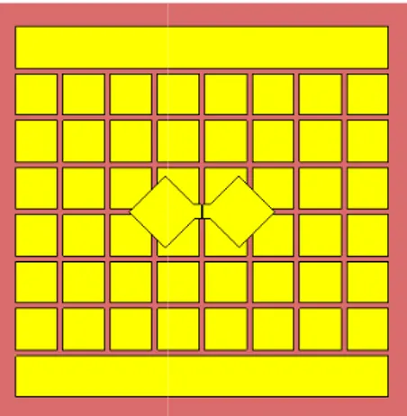
Fig. 1. Diamond Dipole.
Fig. 2. Antenna with Classical AMC
Fig. 3. Antenna with the Hybrid AM
th Broadside
gaud
1 ris, France France Reflector. MC Reflector.The dimensions of the unit cell in the mm, g = 1 mm, where w is the length of the is the distance between two consecutive pa that there is no via in the structure. The AMC is FR4 Epoxy (h = 3.2 mm, εr = 4.1,
above dimensions allow a zero reflection f GHz. At this frequency, the patches beha conductor. As the number of unit cells of A bandwidth of the antenna increases. The si thus a compromise between optimum bandw shown in Fig. 2, an 8 x 8 cells configura designed using unit cell as defined above is The size of FR4 substrate is 75 mm x 75 m antenna substrate is also taken identical substrate. The AMC is placed at a distance antenna. The overall thickness of the antenna III. RESULTS AND DISCUSS
The antenna has been simulated using Studio (Transient solver). The antenna is input port into the gap S. The bandwidth i array behaves as a magnetic conductor is 5.84 GHz) around the zero reflection phase
Fig. 4. Magnitude of reflection coefficient versus freq
Fig. 5. Realized gain in broadside direction versus freq
As seen in Fig. 4, the blue trace gives th reflection coefficient for diamond dipole classical AMC reflector. The impedance ban
AMC are w = 7.4 square patch and g atches. It is noticed substrate used for
tan δ = 0.02). The
frequency at f0 = 5
ave as a magnetic AMC increases, the ize of the AMC is width and size. As ation of the AMC s used in this case. mm. The size of the to that of AMC of 2 mm from the a is then 6.78 mm. SION g CST Microwave fed by a discrete in which the patch 1.61 GHz (4.23 - frequency. quency. quency. he magnitude of the e backed with a ndwidth defined by |S11| < - 10 dB is 2 GHz (4.2 between 6.8 and 7 GHz. On ob various frequencies in the ban radiation lobe splits up around 5 in blue trace by plotting the broadside direction. The max bandwidth is observed to be 7.4 Using the technique detai currents which lead to destru radiation are located in the la AMC. In order to change the metallic strip as shown in F respectively. Thus, the AMC magnetic and electrical cond reflector. When the antenna is impedance bandwidth of the n GHz (4.2 - 6 GHz) with a sec GHz, as seen plotted in red t consideration both bands, ba improved. Fig. 4 also shows t does not have an adverse effec antenna. The introduction o distribution of the currents on destructive contribution in the This restores the radiation in br trace in Fig. 5. This antenna pattern in its entire impedance of the antenna is 8.3 dB.
IV. CO
In this paper, a wideband a discussed. The problem of spl placed over AMC is investigate by cancelling the contribution the magnetic reflector. The re by an overall thickness of a te operating frequency. This ante bandwidth and ensures a broa whole bandwidth.
V. ACKNO
This work is supported by by the IDEX Paris-Saclay, ANR
REFER [1] D. Sievenpiper, L. Zhang, R. Yablonovitch, “High-impedanc forbidden frequency band,” Mic Transactions on , vol. 47, no. 11, [2] R. M. Mateos, C. Craeye and G. antenna,” Microwave and Optic pp. 2615-2619, 2006.
[3] L. Akhoondzadeh-Asl, D. Kern Dipoles on Electromagnetic Ba Propagation, IEEE Transactions 2007.
[4] A. C. Lepage, J. Sarrazin an Antennas with High Impeda Millimeter Wave Circuits and S pp. 69-73.
- 6.2 GHz) with a second band bserving the radiation patterns on ndwidth, it is seen that the main d 5.7 GHz. This is shown in Fig. e realized gain of the antenna in ximum gain in the impedance 4 dB.
iled in [4], it is found that the uctive interference in broadside ast two rows of patches in the distribution of these currents, a Fig. 3 replaces the two rows
reflector is now comprised of ductor and is called a hybrid coupled to the hybrid AMC, the new device is observed to be 1.8 cond band between 6.3 and 6.9 trace in Fig 4. When taking in andwidth has been marginally that changing the AMC pattern ct on the input impedance of the of metallic strip changes the
n AMC in order to cancel the e broadside radiation direction. roadside direction as seen in red
thus has a broadside radiation bandwidth. The maximum gain
ONCLUSION
antenna with a hybrid reflector is lit radiation patterns for dipoles ed and the problem was resolved of destructive currents found on esulting antenna is characterized enth of wavelength at the lowest enna offers a larger impedance adside radiation pattern over its
OWLEDGEMENT
the NanoDesign project funded R-11-IDEX-0003-02.
RENCES
F. J. Broas, N. Alexopolous and E. ce electromagnetic surfaces with a crowave Theory and Techniques, IEEE , pp. 2059-2074, 1999.
Toso, “High-gain wideband low-profile cal Technology Letters, vol. 48, no. 12, n, P. Hall and D. Werner, “Wideband andgap Ground Planes,” Antennas and on, vol. 55, no. 9, pp. 2426-2434, Sept nd X. Begaud, “Wideband Directive ance Surfaces,” in Microwave and ystems, John Wiley & Sons,Ltd., 2013,

![[PDF] Cours de bases de données PL SQL : Procédures stockées et Trigger | Cours informatique](data:image/gif;base64,R0lGODlhAQABAIAAAP///wAAACH5BAEAAAAALAAAAAABAAEAAAICRAEAOw==)