HAL Id: hal-01241732
https://hal.inria.fr/hal-01241732
Submitted on 10 Dec 2015
HAL is a multi-disciplinary open access
archive for the deposit and dissemination of
sci-entific research documents, whether they are
pub-lished or not. The documents may come from
teaching and research institutions in France or
abroad, or from public or private research centers.
L’archive ouverte pluridisciplinaire HAL, est
destinée au dépôt et à la diffusion de documents
scientifiques de niveau recherche, publiés ou non,
émanant des établissements d’enseignement et de
recherche français ou étrangers, des laboratoires
publics ou privés.
An inorbit active debris removal mission
-REMOVEDEBRIS: Pre-Launch update
Jason Forshaw, Guglielmo Aglietti, Nimal Navarathinam, Haval Kadhem,
Thierry Salmon, Eric Joffre, Thomas Chabot, Ingo Retat, Robert Axthelm,
Simon Barraclough, et al.
To cite this version:
Jason Forshaw, Guglielmo Aglietti, Nimal Navarathinam, Haval Kadhem, Thierry Salmon, et al.. An
in-orbit active debris removal mission - REMOVEDEBRIS: Pre-Launch update. Int. Astronautical
Congress, IAC’2015, Oct 2015, Jerusalem, Israel. �hal-01241732�
IAC-15,A6,6,3,x28744
AN IN-ORBIT ACTIVE DEBRIS REMOVAL MISSION - REMOVEDEBRIS:
PRE-LAUNCH UPDATE
Jason L. Forshaw1,∗, Guglielmo Aglietti2
Surrey Space Centre, Department of Electronic Engineering, University of Surrey, Guildford, UK
Nimal Navarathinam, Haval Kadhem
Surrey Satellite Technology Limited (SSTL), Guildford, UK
Thierry Salmona,Eric Joffreb,Thomas Chabotc,Ingo Retatd,Robert Axthelmd,Simon Barracloughe,Andrew Ratcliffee
Airbus Defence and Space (DS):aBordeaux, France;bLes Mureaux, France;cToulouse, France;dBremen, Germany;eStevenage, UK
Cesar Bernalf, Franc¸ois Chaumetteg, Alexandre Pollinih, Willem H. Steyni
fInnovative Solutions In Space (ISIS), Netherlands;gInria, France;hCSEM, Switzerland;iESL, Stellenbosch University, South Africa
ABSTRACT
Since the beginning of the space era, a huge amount of debris has progressively been generated. Most of the objects launched into space are still orbiting the Earth and today these objects represent a threat as the presence of space debris incurs risk of collision and damage to operational satellites. A credible solution has emerged over the recent years: actively removing debris objects by capturing them and disposing of them.
This paper provides an update to the mission baseline and concept of operations of the EC FP7 RemoveDEBRIS mission drawing on the expertise of some of Europe’s most prominent space institutions in order to demonstrate key active debris remove (ADR) technologies in a low-cost ambitious manner. The mission will consist of a microsatellite platform (chaser) that ejects 2 CubeSats (targets). These targets will assist with a range of strategically important ADR technology demonstrations including net capture, harpoon capture and vision-based navigation using a standard camera and LiDAR. The chaser will also host a drag sail for orbital lifetime reduction.
The mission baseline has been revised to take into account feedback from international and national space policy providers in terms of risk and compliance and a suitable launch option is selected. A launch in late 2016 is targeted. The payload flight models are currently scheduled to be delivered in late 2015 for platform integration (AIT) and subsequent EVT phases in early 2016. The RemoveDEBRIS mission aims to be one of the world’s first in-orbit demonstrations of key technologies for active debris removal and is a vital prerequisite to achieving the ultimate goal of a cleaner Earth orbital environment.
Keywords: debris removal, ADR, deorbiting, net, harpoon, vision-based navigation, dragsail
I. INTRODUCTION
R
emovedebris is a low cost mission aiming to perform key Active Debris Removal (ADR) technology demonstrations including the use of a net, a harpoon, vision-based navigation and a dragsail in a realistic space operational environment, due for launch in 2016. For the purposes of the mission CubeSats are ejected then used as targets instead of real space debris, which∗Corresponding Author. Tel.:+44 (0)1483 68 6307
Email addresses: [email protected], [email protected]
URL: www.surrey.ac.uk/ssc/
1SSC Project Manager, Research Fellow (Spacecraft and GNC) 2Principal Investigator, Professor of Spacecraft Structures
is an important step towards a fully operational ADR mission. This paper presents an update on the preliminary design for the RemoveDEBRIS mission from [1, 2], which is currently progressing through its design phases.
The project consortium partners with their responsibilities are given in Table 1.
I.1. Literature
In the field of ADR, there are a wide range of conceptual studies. ESA has produced a range of CleanSpace roadmaps, two of which focus on (a) space debris mitigation and (b) tech-nologies for space debris remediation. ESA’s service orientated ADR (SOADR) design phases involved the analysis of a mis-sion that could remove very heavy debris from orbit examining
Table 1: RemoveDebris Consortium Partners.†vision-based
navigation
Partner Responsibility
SSC (Surrey Space Centre) Project management, CubeSats, dragsail, harpoon target assembly
SSTL Platform technical lead,
operations
Airbus DS Germany Net
Airbus DS France Mission and systems technical lead, VBN†
Airbus DS UK Harpoon
ISIS CubeSat deployers
CSEM LiDAR camera
Inria VBN algorithms
Stellenbosch University CubeSat avionics
both the technical challenges and the business aspects of mul-tiple ADR missions [3, 4, 5]. ESA has conducted industrial phase-A studies, as well as internal exercises as part of the ‘e.Deorbit’ programme, an element of the agency CleanSpace initiative [6]. ESA’s Satellite Servicing Building Blocks (SBB) study originally examined remote maintenance of geostationary telecommunications satellites using a robotic arm [7]. Aviospace have been involved with some ADR studies. The Capture and De-orbiting Technologies (CADET) study examined attitude estimation and non-cooperative approach using a visual and infra-red system. Airbus’s and Aviospace’s Heavy Active Debris Removal (HADR) study examined trade-offs for different ADR technologies, especially including flexible link capture systems. In addition to the various conceptual studies, a range of mis-sions are planning to test specific ADR technologies. DLR’s (German space agency) DEOS (Deutsche Orbital Servicing Mis-sion) aims to rendezvous with a non-cooperative and tumbling spacecraft by means of a robotic manipulator system accommo-dated on a servicing satellite [8]. CleanSpace One, a collabo-ration with EPFL and Swiss Space Systems (S3), aims to use microsatellites with a robotic arm to demonstrate ADR technolo-gies [9]. Other missions of interest include the First European System for Active Debris Removal with Nets (ADR1EN), which aims to validate and qualify a net for space and BETS (pro-pellantless deorbiting of space debris by bare electrodynamic tethers).
Among research programmes from major space agencies, there is also a range of smaller subsets of ADR literature. Chamot at MIT and EPFL has considered the design of three dis-tinct architectures for debris removal depending on how reusable the chaser vehicle is [10]. The ion-beam shepherd is a poten-tial debris removal solution that has been discussed extensively [11]. In addition, a focus on tether dynamics between chaser and target is becoming a wider area of interest [4, 12, 13].
As mentioned, robotic arms have been considered in several past studies. Airbus DS has spent significant resources in the design of robotic arm, net [14], and harpoon demonstrators for
use in space, which are alternatives to the robotic arm. The net, in particular, is considered by some studies to be the most robust method for debris removal, requiring the least knowledge about the target object [4]. The RemoveDEBRIS mission aims to demonstrate these technologies for the first time in space. Airbus DS are also involved in the development of vision-based relative navigation systems, which would be necessary for future debris removal missions [15, 16].
I.2. Paper Structure
Section II details the mission and systems engineering aspects giving information on the primary experiments. It also gives information on orbit selection and deorbiting times. Section III outlines the high level design of the platform. Section IV examines the CubeSats in the mission. Section V details the individual payload design. Finally, Section VI concludes the paper and outlines key contributions to the field.
II. MISSION II.1. In-orbit Demonstrations
This section details the several in-orbit demonstrations in the mission. The three primary experiments are performed se-quentially; with data from each being downloaded before the commencement of the next experiment. There is expected to be 6 month of mission operations.
II.1.1. Net Experiment
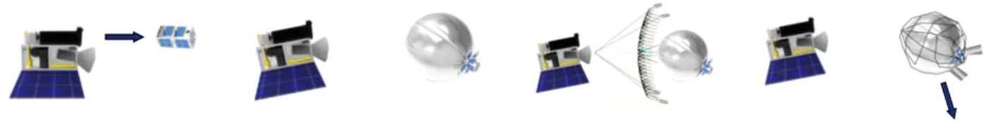
The net scenario is shown in Figure 1 and is designed to help mature net capture technology in space. In this experiment, ini-tially the first CubeSat (net), DS-1, is ejected by the platform at a low velocity (∼ 5 cm/s). DS-1 proceeds to inflate a balloon which, as well as acting as a deorbiting technology, provides a larger target area. A net from the platform is then ejected when the DS-1 is at 7 m distance. Once the net hits the target, de-ployment masses at the end of the net wrap around and entangle the target and motor driven winches reel in the neck of the net preventing re-opening of the net. The CubeSat is then left to deorbit at an accelerated rate due to the large surface area of the balloon. During the net demonstration, two supervision cameras record images which are downloaded afterwards to ground to assess the success of the net demonstration.
II.1.2. Harpoon (HTA) Experiment
The harpoon scenario in Figure 2 uses a deployable target that extends outwards from the platform which is used as a target for the harpoon. The harpoon and the deployable target form the harpoon target assembly (HTA). The distance for harpoon firing is 1.5 m on a 10 × 10 cm target. The harpoon is designed with a flip-out locking mechanism that prevents the tether from pulling out of the target. As for net and harpoon demonstrations, success will be assessed by the images collected by the 2 supervision cameras up to 100 f ps.
Fig. 1: Net Experiment. This figure shows the sequence in the net experiment: (a) DS-1 CubeSat ejection, (b) balloon inflation, (c) net capture, (d) deorbiting.
Fig. 2: Harpoon Experiment. This figure shows the sequence in the harpoon experiment: (a) initial configuration, (b) deployable target deployed, (c) harpoon capture.
Fig. 3: VBN Experiment. This figure shows the sequence in the VBN experiment: (a) DS-2 CubeSat ejection, (b) VBN manoeuvres.
II.1.3. VBN Experiment
The VBN experiment is shown in Figure 3. In this experiment, the second CubeSat, DS-2, is ejected by the platform at very low velocity (∼ 2 cm/s) out of the orbit plan (AoA: 110◦, bank angle: 80◦). The deployment direction is defined to comply with safety constraints and VBN demonstration needs (lightning, background, range). The VBN system (including LiDAR) uses the previous net and harpoon experiments to calibrate itself. The DS-2 deployment direction enables to meet VBN objectives without need of platform boost. Platform attitude needs to be controlled in open loop only. Data, imagery and GPS data collected during VBN demonstration over few orbits are later post-processed on ground.
II.1.4. Other Experiments
The RemoveDEBRIS mission, in addition to performing the three primary experiments, also aims to test a few other devel-oped technologies. These include new platform avionics and a 10 m2drag sail. These experiments are to be performed after the
primary experiments and are explained in further depth in the payload section.
II.2. Mission, Launch and Orbit II.2.1. Orbit Selection
One possibility under consideration is that the RemoveDE-BRIS platform could be launched from the ISS. The plat-form would transit inside ISS before being ejected from the
Japanese module using the Special Purpose Dexterous Manip-ulator (SPDM). Hence, the mission baseline orbit is the ISS orbit (51.6◦) and approximately a 400 km altitude, circular at the beginning. For further information about the mission trade-offs see [17].
II.2.2. Mission Timeline
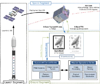
Figure 4 shows the mission space segment for the proposed launch. Operations for the RemoveDEBRIS mission will be car-ried out from SSTL’s Mission Operations Centre in Guildford. SSTL’s standard operations procedures will be used, which are compatible with the SSTL designed platform operational require-ments and characteristics. Figure 5 is the mission timeline which shows the order in which experiments are to be performed. II.2.3. Deorbit Times
The mission aims to comply with legal requirements for de-orbiting including that objects placed in LEO (low Earth orbit) should naturally deorbit within 25 years, a key requirement of the UK Outer Space Act (OSA, 1986) and the French Space Operations Act (2008).
Various packages have been used to calculate the deorbit time for all objects placed in space including ESA’s DRAMA (debris risk assessment and mitigation analysis) and CNES’s STELA (semi-analytic tool for end of life analysis) [18]. In this research we present the results from STELA for each space object. Var-ious interdisciplinary topics are involved in the evaluation of the orbital lifetime, including solar activity prediction and its
Fig. 4: Overview of Space Segment. This figure shows the mission space segment.
Fig. 5: Mission Timeline. This figure shows the order in which experiments are performed.
Table 2: RemoveDEBRIS Deorbit Times. From STELA (in 2016, from 400 km).
Object Nominal Orbit Lifetime (yrs)
Platform (RemoveSAT) 2
DS-1 (Net) 0.4
DS-2 (VBN) 0.5
Net (alone) 0.5
Harpoon (alone) 2
effect on the atmospheric density, solar radiation pressure and drag modelling, third body effects as well as complex gravity models implementation. However, semi-analytical propagation techniques allow to evaluate the reentry duration in a reasonable computational time [19]. STELA has been validated by compar-ison to simulations based on fully numerical integration as well as real trajectories [20]. Table 2 summarises the preliminary results obtained. The results show that the compliance to the 25 years rule is easily achieved for all the objects, even for the main platform when the drag sail is not deployed.
III. REMOVESAT: PLATFORM
The RemoveDebris platform, RemoveSAT, utilises the next generation of low earth orbit spacecraft avionics systems and structural design being developed at SSTL called the X-Series [21]. The X-Series architecture is based on a modular and expandable philosophy that utilises common modules. This allows the system to be adaptable to varying mission applications and requirements.
III.1. Design Principles and Drivers
The X-Series platforms are being developed with some key drivers and principles in mind. These are a combination of (a) principles that SSTL have employed successfully in delivering small satellites in the last 30 years, and (b) new approaches that are enabled by SSTL’s evolution as a company in the last 10 years, specifically the recently developed in house capabilities for batch/mass production and automated test. These key drivers and principles can be summarised as follows:
• The use of mature, well developed non space specific pro-tocols such as CAN and LIN.
• On board autonomy, resulting in the elimination of the need for expensive, constantly manned ground segments. • Robustness and redundancy; simple and robust operational
modes that deliver competitive payload availability perfor-mance with multiple backup functionality and equipments on board to assure mission lifetime and guard against un-foreseen and random outages and failures.
• The use of commercial-off-the-shelf (COTS) components and technologies building on over 30 years of successful implementation on operational missions.
• Modularity; investing the development of only a few key new systems that can be arranged in configurations to de-liver a wide variety of performance and capacity variations depending on mission requirements.
• Low recurrent costs at ‘unit’ level; maximising the use of automated manufacture and test capabilities to reduce expensive manpower costs, thereby achieving an extremely low unit level cost.
From an operations concept and fault detection, isolation and recovery (FDIR) point of view, the new design is functionally identical to the previous generation of SSTL spacecraft thus benefiting from the process of continuous refinement over three decades of SSTL small satellite mission design and operations. III.2. X50 Structure
The RemoveDebris platform is a derivative of the SSTL X-series platform that has been customised for an ISS deployment. The RemoveDebris mission provides an excellent opportunity to demonstrate the adaptability and modularity of this new platform. The primary function of the platform structure is to provide ap-propriate accommodation and environmental conditions for the
payload and avionics; its main tasks include: (a) interfacing with the launch vehicle, (b) providing appropriate accommoda-tion and alignment of the payloads, (c) providing appropriate accommodation for the avionics subsystems, (d) maintaining acceptable environmental conditions for sub-system protection during launch, (e) maintaining acceptable environmental condi-tions for on-orbit sub-system operation.
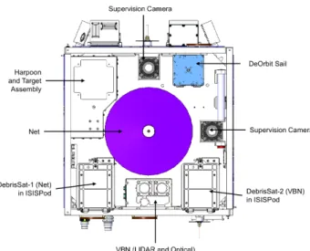
The platform is based on four side panels, a payload panel, and a separation panel as shown in Figure 6. Payloads are mounted either on the payload panel within the payload volume atop the avionics bay or along the side panels. This is in line with the mission profile and operations concept which essentially requires all payloads to be deployed in the same direction (and monitored in that direction).
Fig. 6: Platform: Overall Structure.
The payload panel is structurally coupled to the four side panels that make up the main supporting structure as shown in Figure 7. The side panel are structurally coupled to the separa-tion panel along their base edges and to each other along their side edges at discrete locations. The side and payload panels are made from aluminium honeycomb sandwich panels while the separation panel is made out of machined aluminium. Three of the four side panels are also populated with solar cells to provide power throughout the orbit.
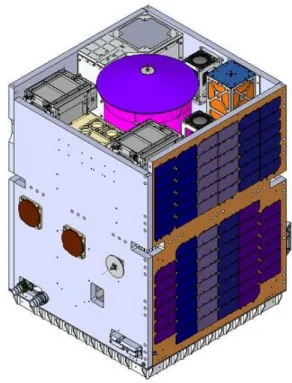
Below the payload panel is platform avionics bay where the platform sub-systems are housed as shown in Figure 8; this in-cludes items such as: magnetometers, magnetorquers, reaction wheels, gyros, on-board computers, GPS receiver, X50 avionics stack, and batteries. Appropriate multi-layer insulation and sec-ond surface mirror tapes will be used to achieve the appropriate thermal environment for the platform and payloads.
Fig. 7: Platform: Payload Accommodation.
Fig. 8: Platform: Internal Accommodation.
The top level specifications for the RemoveDebris Platform are captured in the Table 3. The overall dimensions of the plat-form and mass have been reduced in order to make it compatible with the ISS Kaber deployment system’s capability.
Table 3: RemoveDEBRIS Platform Specification.
Parameter Value
Mass < 100 kg
Payload Mass ∼ 40 kg
Envelope 0.55 m × 0.55 m × 0.72 m Payload Downlink 2 Mbps (S-Band)
Uplink 19.2 kbps
Data Storage 2 × 64 GB III.3. X50 Avionics and Heritage Hardware
The X50 avionics system builds on the modular and expand-able philosophy and also improves manufacturability, integra-tion, and testing. The avionics system is based on a cardframe
structure with backplane interconnections as shown in Figure 9. This results in far less labour to interconnect the modules and also simplifies integration and module insertion and replace-ment. The new modules that have been developed for X50 avionics include: (a) Power Distribution Module (PDM), (b) Battery Charge Module (BCM), (c) S-band Transmitter/Receiver (STRx), (d) Payload Interface Unit (PIU). These cards are lo-cated in the cardframe using wedgelocks for easy insertion and extraction. The power and data interconnections are via the back-plane, keeping the front of the cardframe free of harness and thus allowing easy module insertion and extraction. The avionics subsystem module cards will be housed in two 7-slot cardframe structures; one cardframe structure is allocated for power cards (BCM and PDM) while the other is allocated for OBDH and STRx cards. Two of each card is flown for redundancy and
Fig. 9: Platform: Card Frame Assembly.
Table 4: RemoveDEBRIS Platform Equipment List and De-sign Status.
Equipment Qty Status
Reaction Wheels 4 Heritage
Sun Sensors 4 Heritage
Magnetorquer rods 3 Heritage
Magnetometer 2 Heritage
Gyros 4 Heritage
Gryo Control Unit 1 Heritage
AOCS Interface Module 2 Heritage GPS: SGR-Axio Receiver 1 Heritage
GPS Patch Antennas 2 Heritage
Power Distribution Module 4 X-Series Battery Charge Module 3 X-Series Body Mounted Solar Panels 3 Heritage
Battery 1 Heritage
S-band Tx/Rx 2 X-Series
S-band Tx Monopoles 4 Heritage
S-band Rx Patches 4 Heritage
S-band Tx Patches 2 Heritage
OBC750 2 Heritage
Payload Interface Unit 2 X-Series 6
protect against failures.
The remainder of the platform is made up of heritage SSTL subsystems and equipments. A full equipment list for the plat-form is included in Table 4.
IV. DEBRISATS: CUBESATS
This section will outline the mission’s CubeSats, the De-briSATs produced by the Surrey Space Centre for which further information can be found in [22]. The CubeSats are ejected from deployers produced by ISIS, Innovative Solutions In Space. IV.1. DS-1: Net CubeSat Hardware
DS-1 is based on a 2U CubeSat with the following dimen-sions: 100 × 100 × 227 mm, where 1U (100 × 100 × 100 mm) is reserved for the avionics and the remaining space is reserved for the inflatable structure. Figure 10 shows the CubeSat struc-ture. Figure 10 [a] shows the structure when the CubeSat is undeployed; the avionics section is on the left and the inflatable part on the right. The avionics section contains: the CubeSat Release System (CRS), the assembly that connects the CubeSat to the deployer before it is ejected, the EPS (power) board, the OBC (flight computer) board. The inflatable section contains: the central inflation connector system housing a cold gas gener-ator (CGG), a solenoid valve. Figure 10 [d] shows the inflated system, where the burn wire is burnt and the inflation system is released by means of high torsion springs. Once the CGG is activated, the booms simultaneously inflate forming the overall balloon structure as in Figure 10 [e] which shows the fully in-flated balloon including wires and membrane which resembles an octahedron tensegrity. As DS-1 has no control system, the CubeSat is free to tumble.
(a) Inner structure
(b) Deployment 2 (c) Full structure
Fig. 10: Net CubeSat (DS-1): Structure
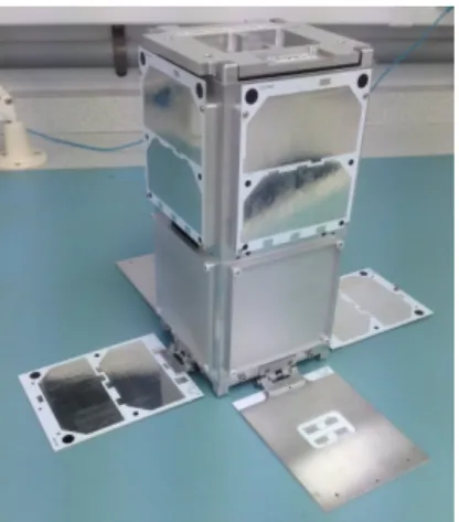
IV.2. DS-2: VBN CubeSat Hardware
In the VBN experiment, the VBN payload on the platform will inspect the VBN CubeSat, DS-2, during a series of manoeuvres at a range of distances and in different light conditions dependent on the orbit. The CubeSat, DS-2, can be seen in Figure 11. The CubeSat is a 2U where avionics are inserted throughout the structure and the bottom part of the structure has 4 deployable panels in the shape of a cross. The deployable panels have no specific function except to make the CubeSat look more like a satellite. This is to enable the VBN algorithms to see something that closer represent a ‘real satellite’ with deployed panels. The avionics on-board include: the GPS board, 3 × OBC boards which contain full 3-axis (3-DoF) attitude control, the EPS board, the burnwire board, an ISL (inter-satellite link) board which enables communications between the CubeSat and the platform (for transmitting back GPS, sensor and camera data), the camera board, and solar cells. The CubeSat also has small markers on the outer surface that can be used for tracking by the VBN algorithms (not shown on photo).
Fig. 11: VBN CubeSat (DS-2): Structure.
IV.3. Avionics
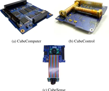
The CubeSat avionics are primarily based on the QB50 avion-ics developed by the Surrey Space Centre and the Electronic Systems Laboratory (ESL) at Stellenbosch University [23]. The QB50 stack, shown in Figure 12 consists of 3 boards, the Cube-Computer, CubeControl and CubeSense boards. The primary boards are shown in Figure 13. The CubeComputer performs the CubeSat processing and contains a 32-bit ARM Cortex-M3 including flash for in-flight reprogramming (dual redundant), an FPGA for flow-through error correction in case of a radiation upset on the memory and a MicroSD card for data storage. The CubeControl controls both magnetometers and samples con-nected sensors. The CubeSense contains both sun and nadir sensors. Not all of the boards are used on each CubeSat; the boards used in each CubeSat are given in Table 5.
Fig. 12: Avionics: QB50 Full Stack. Showing 2 distinct units.
(a) CubeComputer (b) CubeControl
(c) CubeSense
Fig. 13: Avionics: Individual Boards
Table 5: CubeSat Avionics Boards. ∗on-board computer, †electrical power system, ‡momentum wheel, ?inter-satellite
link
Cubesat Board
DS-1 (Net) CubeComputer (OBC∗) board
EPS†board
CGG & valve control board
DS-2 (VBN) CubeComputer (OBC)
CubeControl (AOCS)+ 3 MW‡board CubeSense (sensor) board
GPS board EPS board Burnwire board ISL?board Camera board
IV.3.1. CubeSat Testing
The CubeSats are undergoing a range of functional and envi-ronmental testing including EQM vibration testing (Figure 14) and inflatable deployment testing (Figure 15).
Fig. 14: CubeSat Testing: Vibration EVT. Left: DS-1 then DS-2 ready for testing. Right: vibration table setup with Cube-Sats inside TestPODs.
Fig. 15: CubeSat Testing: DS-1 Inflatable Deployment Test.
IV.4. Deployer
The 2 target CubeSats for the RemoveDEBRIS project are carried onboard the host satellite inside 2 dedicated CubeSat dispensers provided by ISIS, Innovative Solutions In Space. For this particular mission ISIS is redesigning its heritage ISIPOD CubeSat dispenser system to meet the specific mission objec-tives for the project. Normally the CubeSat dispensers deploy the CubeSats into orbit from an upper stage of a rocket and are activated within the first hour of the launch. For RemoveDE-BRIS, the CubeSats will be deployed from a host satellite, which causes specific integration and accommodation challenges and in addition the CubeSats will be deployed long after launch. This has some key implications for the dispenser system. The dispensers will be outfitted with a special CRS interface between each CubeSat and its deployer. The function of the interface is twofold: (a) provide an interface to enable the host satellite to charge the batteries of the target CubeSats, (b) provide a cutting mechanism that will separate the CubeSats from the deployers and eject them with a specific low-speed deployment velocity. Ideally, the ejection speed is 2 cm/s for the VBN demonstration and 5 cm/s for the net demonstration.
V. PAYLOADS V.1. Net
The Net Capture Mechanism (NETCAM) will be the first in-orbital-flight demonstration for a system catching large orbital debris via a high strength net. On the Remove Debris mission artificial orbital debris of some 2 kg and 1 m diameter will be captured, however, the 5 m net used for this demonstration is already capable to capture debris in the 1.5 m range and to return up to several 100 kg to Earth on a destructive trajectory. This experiment will be the next big step after successful demonstra-tions of the net deployment in both drop tower and on a parabolic flight.
V.1.1. Net Hardware
The NETCAM design is shown in Figure 16. The NETCAM has 275 mm diameter and a height of 225 mm. The total weight target is 6.5 kg. The high strength fibre net will be deployed by concentric accommodated flight weights and a central lid, inflat-ing the net. Motors and winches in the weights are used to close the net after successful capture of the debris. The net deployment and closure will be achieved via redundant mechanisms.
Fig. 16: NETCAM Payload.
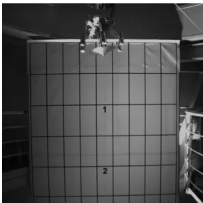
V.1.2. Net Testing
The net has undergone a range of functional testing including experimentation in the Bremen drop tower and the net closure
Fig. 17: Net Testing: Vibration EVT.
in the Novespace A300 parabolic flight (Figure 18). A thorough test programme comprising thermal vacuum, vibration testing and net deployment testing shall ensure mission success. In July 2015 the NETCAM EQM vibration testing has been performed (Figure 17) followed by a deployment test in the Bremen drop tower (Figure 19).
Fig. 18: Net Testing: Novespace A300 Parabolic Flight. Tar-get capture and closure of 1 m net demonstrated in parabolic flight (capture top, closure bottom).
Fig. 19: Net Testing: Deployment Test in Bremen Drop Tower.
V.2. Harpoon (HTA)
The harpoon target assembly (HTA) consists of the deploy-able target structure and the harpoon capture system (HCS). The former is being provided by SSC, the latter is being developed by Airbus DS Stevenage as a mission enabling capture system for future ADR missions. The RemoveDEBRIS mission serves to raise the TRL of key elements of the harpoon capture system, providing a platform to test the technology in the space environ-ment. The HCS is designed to establish a hard point attachment to debris and provide a link to the chaser via a flexible coupling. A flexible link allows for deployment from a stand-off distance, reducing the risk to the chaser during stabilisation or towing. The HCS has several features which led to its selection:
• Low mass and volume allowing the possibility to host mul-tiple harpoons on a single spacecraft
• Relative simplicity leading to high reliability, low develop-ment risk and low cost
• High firing speed ensuring compatibility with objects spin-ning at fast rates
• Ability to perform comprehensive characterisation of cap-ture on ground
V.2.1. Deployable Target Hardware
The deployable target structure is shown in Figure 20 where the harpoon is mounted at the top and the deployable boom at the bottom. As the deployable boom (a coiled CPFR mono-stable boom) extends, the target panel moves out from the structure and platform. At 1.5 m the boom stops extended and the harpoon firing experiment is performed. The experiment is captured on the dual supervision cameras on the platform. After the experiment, the boom is retracted to prevent interference with the dragsail for when the dragsail boom is deployed later in the mission. Harpoon Deployable Target Structure Deployable Boom Deployable Target Panel Deployment Direction Target Connection Mechanism
Fig. 20: Overview of the HTA Payload.
V.2.2. Harpoon Hardware
The baseline harpoon concept for large debris items was devel-oped under internal Airbus R&D [24] and a small scale demon-strator has been accepted for flight test on RemoveDEBRIS. The HCS designed for RemoveDEBRIS is composed of 3 main elements: Deployer, Projectile and Tether. The flight harpoon payload is shown in Figure 21. The base area of the assembly is contained within an A4 sheet of paper.
Fig. 21: RemoveDebris Harpoon Payload.
The Deployer imparts sufficient velocity to the projectile for penetration of the target structure. Extensive ground character-isation has established that 20 m/s is required to penetrate the target’s aluminium honeycomb panels. Energy is provided to the system by a gas generator mounted at the back of the De-ployer. Upon activating gas is released into the chamber volume, increasing the force applied against a piston. The piston is held by a tear pin until a set failure stress is reached, resulting in the piston propelling the projectile out of the Deployer. To provide fault tolerance against premature deployment, a hold down and release (HDR) mechanism is to be incorporated on the flight model. The elements of the harpoon firing process are shown in Figure 22.
Fig. 22: Harpoon Firing Process.
V.2.3. Harpoon Projectile
The projectile is shown in Figure 23. The projectile is de-signed to penetrate the target panel and successfully deploy a set of barbs on the opposite side, providing the crucial locking interface with the target. A shroud protects the barbs during the penetration of the structure. A key driver has been to ensure 10
that the overall length of the payload is at a minimum. The evolution of the projectile is shown in Figure 24. Verification of the design has been performed in development testing with the firing system and target panels, with the final version on the right of the figure.
Fig. 23: RemoveDEBRIS Harpoon Projectile.
Fig. 24: RemoveDebris Projectile Prototypes and Evolution. Free release of the tether is a key influence on the accuracy of the HCS. Tests have been performed to select the ideal spool arrangement and mounting location to minimise inaccuracy in impact location. The tether attachment is located at the end of the projectile. Hardware testing has shown that this arrangement minimises the disturbance the tether may have on the harpoon flight.
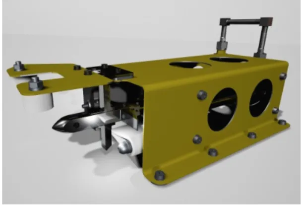
V.2.4. Harpoon and HTA Testing
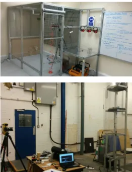
A significant benefit of the harpoon is that validation of many aspects can be performed on ground in the Airbus DS test range shown in Figure 25. The availability of a test range allows for many of the design challenges to be overcome and characterised on ground before use on-orbit. The test rig has allowed many design variables to be tested; projectile configuration, panel type, panel offset. The availability of the test rig has allowed the rapid prototype development and identification of key design variables that are difficult to identify using classical design approaches.
The HTA is currently undergoing functional testing. The structural model can be seen in Figure 26 where the deployable target casing and the target panel can be seen separately. Fig-ure 27 shows a deployment test where the harpoon is fired at the deployed assembly. The harpoon can just be seen on using a high speed camera on its way to the target panel.
Fig. 25: Airbus DS Stevenage Harpoon Test Facilities.
Fig. 26: HTA Structural Model.
Mock Harpoon HTA Mock Structure Deployable Target Panel Deployment Direction Extended CPFR Boom (1.5 m total length)
V.3. VBN
Airbus Defence and Space has been strongly involved in the design of Vision-Based Navigation (VBN) systems over the last years, with particular focus on applications such as plane-tary landing and orbital rendezvous, typically in the context of Mars Sample Return missions [16]. Based on this background and due to the increasing interest in Active Debris Removal (ADR), solutions for autonomous, vision-based navigation for non-cooperative rendezvous have been investigated. Dedicated image processing (IP) and navigation algorithms have been de-signed at Airbus Defence and Space and INRIA to meet this specific case, and some of them have already been tested over synthetic images and actual pictures of various spacecraft [15]. As the next step, the VBN demonstration onboard RemoveDE-BRIS will validate vision-based navigation equipment and al-gorithms, through ground-based processing of actual images acquired in flight, in conditions fully representative of ADR. The VBN demonstration will thus fulfil the following objectives: • Demonstrate state-of-the-art image processing and naviga-tion algorithms based on actual flight data, acquired through two different but complementary sensors: a standard cam-era, and a flash imaging LiDAR.
• Validate a flash imaging LiDAR in flight
• Provide an on-board processing function in order to support navigation.
V.3.1. VBN Hardware
Images will be captured from two main optical sensors: a con-ventional 2D camera (passive imager) and an innovative flash imaging LiDAR (active imager), developed by the Swiss Centre for Electronics and Microsystems (CSEM). It will be a scaled-down version of a 3D imaging device developed and tested in the frame of ‘Fosternav’ FP7 project for the European Com-mission focusing on landing and rendezvous applications. This architecture has the particularity of providing ranging capability
Fig. 28: VBN Hardware. Showing VBN Sensor and DS-2.
by measuring the phase difference of two signals. It will be the first time in Europe that a device based on flash imaging LiDAR technology - considered to be a key enabling technology by the space community for the future success of exploration missions with landing, rendezvous and rover navigation phases - will be used for debris tracking and capture control. Such experiment will allow Europe to master state of the art technologies in the field of 3D vision sensors for GNC systems. The hardware is show in Figure 28.
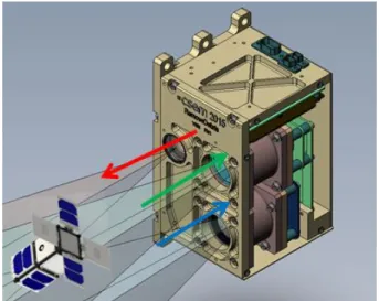
V.3.2. VBN Demonstration Scenario
In a first step, 3D and 2D images will be captured from the start of the operational phase, i.e. when DS-1 is released for preliminary checks, monitoring purposes, as well as a first col-lection of data covering the net experiment. In a second step, the VBN demonstration per se will start, and will consist in capturing images of DS-2 from various distances and over large duration in order to make sure that the widest range of visual configurations (in terms of distance to target, relative attitude, light conditions, background) is reached. This will make the ex-periment as much demonstrative as possible, while meeting the classical duration and cost constraints of a low-cost demonstra-tion mission. Extensive trade-offs considering various criteria such as mission and platform complexity, safety, background, illumination conditions, relative drift led to the choice of a tra-jectory which is simple and passively safe but still allows a wide range of visual configurations between RemoveSAT and DS-2. This baseline trajectory is illustrated in Figure 29 hereafter. As DS-2 is drifting away from RemoveSAT, the 3D and 2D cameras will continue to collect imagery as long as Line-Of-Sight (LOS) is maintained. Image data will be downloaded during ground contact windows.
Fig. 29: VBN Demonstration Trajectory. Showing relative trajectory.
V.3.3. On-ground Processing
All the data acquired during the VBN experiment will be processed on the ground with innovative IP algorithms (e.g. 2D/3D and 3D/3D matching techniques) and a specifically tuned navigation algorithms based on an Extended Kalman Filter able to fuse data from different sensors (e.g. camera images and attitude sensing data).
Differential GPS and onboard attitude estimation software will also provide ‘ground truth’ data against which the navigation 12
Fig. 30: 2D/ 3D Matching.
algorithms will be compared for validation and performance assessment. Post-processing activities will allow demonstration of performances of innovative 2D camera based navigation and 3D camera based navigation, allowing not only estimation of relative position and velocity but also relative attitude, one of the key drivers of successful capture of an uncooperative target. V.4. Dragsail
The RemoveDEBRIS platform will have a Surrey Space Cen-tre dragsail payload. The dragsail concept can be seen in Fig-ure 31. The dragsail consists of 2 parts: an inflatable deployer which extends the sail away from the platform (preventing the sail from hitting any overhanging platform hardware e.g. anten-nas), and a extension mechanism which uses a motor to unfurl carbon fibre booms that hold the sail membrane. Figure 32 shows an external and internal view of the dragsail. The de-ployer is an inflatable mechanism that deploys to a length of 1 m and self-hardens. The extension mechanism consists of four booms rolled into a central distributor that allows controlled unfurling of the sail.
V.5. Supervision Cameras
RemoveDebris platform will house two Supervision Cam-eras each with a 60 degree field of view (FoV). The Supervi-sion Cameras are based on SSTL’s heritage system, shown in Figure 33, that was flown on the Technology Demonstration Satellite-1 (TDS-1) launched in July, 2014. This camera system uses Commercial Off The Shelf (COTS) technology combining a colour CMOS camera with a high performance machine vi-sion lens capable of delivering video. Both camera and lens are stripped down and all unsuitable components removed before being ruggedised during reassembly to survive the vibration and shock loads experienced during launch as well as making it suitable for the space environment. The camera system will be optimised to give a depth of field capable of meeting the performance requirements for the demonstrations. Customised mounting brackets will be used to point the camera in the re-quired direction for the demonstrations. The cameras will use a CameraLink interface to the PIU. They will acquire 8 bit images that are 1280×1024 pixels in size with varying frame rates based on the demonstration requirements. Figure 34 shows an image taken of the Antenna Pointing Mechanism (APM) on TDS-1 just after launch with Earth in the background.
Fig. 31: Dragsail Concept.
(a) Outer Structure (b) Inner Structure
Fig. 32: Dragsail Payload
Fig. 33: Supervision Camera. With housing.
Fig. 34: Supervision Camera. Image from camera on TDS-1 of APM with Earth in the background.
VI. CONCLUSIONS
RemoveDEBRIS is aimed at performing key ADR technol-ogy demonstrations (e.g capture, deorbiting) representative of an operational scenario during a low-cost mission using novel key technologies for future missions in what promises to be the first ADR technology mission internationally. This paper has pro-vided a pre-launch update to the mission, platform and payloads. Key ADR technologies include the use of net and harpoon to capture debris, vision-based navigation to target debris and a dragsail for deorbiting. Although this is not a fully-edged ADR mission as CubeSats are utilised as artificial debris targets, the project is an important step towards a fully operational ADR mission; the mission proposed is a vital prerequisite in achieving the ultimate goal of a cleaner Earth orbital environment.
VII. ACKNOWLEDGEMENTS
This research is supported by the European Commission FP7-SPACE-2013-1 (project 607099) ‘RemoveDEBRIS - A Low Cost Active Debris Removal Demonstration Mission’, a consortium partnership project consisting of: Surrey Space Cen-tre (University of Surrey), SSTL, Airbus DS (formerly Astrium) GmbH, Airbus SAS, Airbus Ltd, ISIS, CSEM, Inria, Stellen-bosch University.
REFERENCES
[1] V. J. Lappas, J. L. Forshaw, L. Visagie, A. Pisseloup, T. Salmon, E. Joffre, T. Chabot, I. Retat, R. Axthelm, S. Barraclough, A. Ratcliffe, A. Bradford, H. Kadhem, N. Navarathinam, J. Rotteveel, C. Bernal, F. Chaumette, A. Pollini, W. H. Steyn, RemoveDEBRIS: An EU low cost demonstration mission to test ADR technologies, in: 65th International Astronautical Congress, Toronto, Canada, 2014.
[2] J. L. Forshaw, V. J. Lappas, A. Pisseloup, T. Salmon, T. Chabot, I. Re-tat, S. Barraclough, A. Bradford, J. Rotteveel, F. Chaumette, A. Pollini, W. H. Steyn, RemoveDEBRIS: A low cost R&D ADR demonstration mission, in: CNES 3rd European Workshop on Space Debris Modeling and Remediation, Paris, France, 2014.
[3] C. Saunders, A. Chiesa, J. L. Forshaw, B. Parreira, R. Biesbroek, Results of a system feasibility study on a heavy active debris removal mission, in: CNES 3rd European Workshop on Space Debris Modeling and Remedia-tion, Paris, France, 2014.
[4] C. Saunders, J. L. Forshaw, V. J. Lappas, A. Chiesa, B. Parreira, R. Bies-broek, Mission and systems design for the debris removal of massive satellites, in: 65th International Astronautical Congress, Toronto, Canada, 2014.
[5] C. Saunders, J. L. Forshaw, V. J. Lappas, D. Wade, D. Iron, R. Biesbroek, Business and economic considerations for service oriented active debris removal missions, in: 65th International Astronautical Congress, Toronto, Canada, 2014.
[6] European Space Agency, e.Deorbit CDF Study Report, Tech. Rep. CDF-134(A), European Space Agency (2012).
[7] C. Cougnet, B. Gerber, C. Heemskerk, K. Kapellos, G. Visentin, On-orbit servicing system of a geo satellite fleet, in: 9th ESA Workshop on Advanced Space Technologies for Robotics and Automation ‘ASTRA 2006’, ESTEC, Netherlands, 2006.
[8] D. Reintsema, B. Sommer, T. Wolf, J. Theater, A. Radthke, W. Naumann, P. Rank, J. Sommer, DEOS - the in-flight technology demonstration of german’s robotics approach to dispose malfunctioned satellites, in: ESA 11th Symposium on Advanced Space Technologies in Robotics and Au-tomation, ESTEC, Netherlands, 2011.
[9] M. Richard, L. Kronig, F. Belloni, S. Rossi, V. Gass, C. Paccolat, J. Thi-ran, S. Araomi, I. Gavrilovich, H. Shea, Uncooperative rendezvous and docking for microsats: The case for cleanspace one, in: 6th International Conference on Recent Advances in Space Technologies (RAST), Istanbul, Turkey, 2013.
[10] B. Chamot, Mission and system architecture design for active removal of rocket bodies in low earth orbit, Master’s thesis, Massachusetts Institute of Technology, US (August 2012).
[11] M. Merino, E. Ahedo, C. Bombardelli, H. Urrutxua, J. Pelaez, L. Sum-merer, Space debris removal with an ion beam shepherd satellite: target-plasma interaction, in: 47th AIAA/ASME/SAE/ASEE Joint Propulsion Conference & Exhibit, San Diego, US, 2011.
[12] L. Z. Jasper, C. R. Seubert, H. Schaub, T. Valery, E. Yutkin, Tethered tug for large low earth orbit debris removal, in: American Institute of Aeronautics and Astronautics Astrodynamics Specialists Conference, no. AAS 12-252, San Diego, US, 2012.
[13] L. Z. Jasper, H. Schaub, Input shaped large thrust maneuver with a tethered debris object, in: 6th European Conference on Space Debris, no. 6a.O-11, ESOC, Darmstadt, Germany, 2013.
[14] Astrium Space Transportation, ROGER Phase-A Final Report Executive Summary, Tech. Rep. ROG-SIBRE-EXS, Astrium Space Transportation (2003).
[15] A. Petit, E. Marchand, K. Kanani., Tracking complex targets for space rendezvous and debris removal applications, in: IEEE/RSJ Conference on Intelligent Robots and Systems, IROS’12, Vilamoura, Portugal, 2012. [16] T. Chabot, E. Kervendal, N. Despre, K. Kanani, P. Vidal, E. Monchieri,
D. Rebuffat, S. Santandrea, J. L. Forshaw, Relative navigation challenges and solutions for autonomous orbital rendezvous, in: EuroGNC 2015, Toulouse, France, 2015.
[17] E. Joffre, J. L. Forshaw, T. Secretin, S. Reynaud, T. Salmon, A. Pisseloup, G. Aglietti, Removedebris - mission analysis for a low cost active debris removal demonstration in 2016, in: 25th International Symposium on Space Flight Dynamics (ISSFD), Munich, Germany, 2015.
[18] Le Fevre et al., Compliance of disposal orbits with the French Space Act: the good practices and the STELA tool, Acta Astronautica 94 (1). [19] Fraysse et al., Long term orbit propagation techniques developed in the
frame of the French Space Act, Journal of Aerospace Engineering, Sci-ences and Applications 4 (4).
[20] C. Bonnal, CNES activities related to space debris, in: P2ROTECT
work-shop, Torino, Italy, 2013.
[21] A. Bradford, L. Gomes, S. Kenyon, D. Stanton, J. Penson, Lowering the cost of space access - a new generation of low cost SSTL platforms, in: 64th International Astronautical Congress, Beijing, China, 2013. [22] J. L. Forshaw, C. Massimiani, M. Richter, A. Viquerat, E. Simons, R. Duke,
G. Aglietti, Surrey space centre: A survey of debris removal research activities, in: 66th International Astronautical Congress, Jerusalem, Israel, 2015.
[23] L. Visagie, J. L. Forshaw, T. E. Frame, V. J. Lappas, W. H. Steyn, A miniaturised attitude control and determination system for the QB50 and SME-SAT missions, in: ESA Guidance, Navigation, and Control Confer-ence, Porto, Portugal, 2014.
[24] J. Reed, S. Barraclough, Development of harpoon system for capturing space debris, in: 6th European Conference on Space Debris, Darmstadt, Germany, 2013.