Effets des éléments d’alliage sur les propriétés de
traction des alliages de base Al-Si-Cu-Mg à température
ambiante et haute
Par Loay Alyaldin
Mémoire présenté à l`Université du Québec à Chicoutimi
en vue de l’obtention du grade de la maîtrise en
ingénierie
Québec, Canada
Effects of alloying elements on room and high
temperature tensile properties of Al-Si-Cu-Mg base
alloys
By Loay Alyaldin
Thesis presented to University of Quebec at Chicoutimi
in partial fulfillment of the requirement for the degree of
master in engineering
Quebec, Canada
Dedicated to my grandparents, my
RÉSUMÉ
Au cours des dernières années, l'aluminium et les alliages d'aluminium ont été largement utilisés dans l’industrie de l'automobile et de l'aérospatiale. Parmi les alliages d'aluminium coulé les plus couramment utilisés, figurent ceux appartenant au système Al-Si. En raison de leurs propriétés mécaniques, de leur légèreté, de leur excellente coulabilité et de leur résistance à la corrosion, ces alliages sont principalement utilisés dans l'ingénierie et dans les applications automobiles. Plus l'aluminium est utilisé dans la production d'un véhicule, plus le poids de celui-ci est diminué et contribue à diminuer sa consommation de carburant, réduisant ainsi la quantité d'émissions nocives dans l'atmosphère.
Les principaux éléments d'alliage dans les alliages Al-Si, en plus du silicium, sont le magnésium et le cuivre. Ceux-ci améliorent la résistance à l'alliage par le phénomène de durcissement par précipitation suite au traitement thermique, grâce à la formation de précipités Al2Cu et Mg2Si. Cependant, la plupart des alliages Al-Si ne conviennent pas aux applications à haute température, car leur résistance à la traction et à la fatigue ne sont pas aussi élevées que souhaitées dans la plage de température 230-350 ° C, qui est la plage de températures souvent atteinte dans les composants du moteur automobile en service. Le principal défi réside dans le fait que la résistance des alliages d'aluminium moulé traitable thermiquement diminue à des températures supérieures à ~200 ° C. Les précipités de Mg2Si et Al2Cu qui maintiennent la résistance élevée de l'alliage habituellement grossissent ou se dissolvent à des températures supérieures à 150 ° C, ce qui entraîne une réduction des performances à haute température et par conséquent limite les applications pratiques. La plupart des alliages moulés Al-Si à ce jour sont destinés pour des applications à des températures qui ne dépassent pas environ 230 ° C.
La résistance des alliages dans des conditions à haute température est améliorée grâce à l'obtention d'une microstructure contenant des intermétalliques thermiquement stables et résistants au grossissement, ce qui peut être obtenu avec l'addition de Ni. Zr et Sc. Le nickel conduit à la formation d'aluminiure de nickel Al3Ni et Al9FeNi en présence de fer. Tandis que le zirconium lui, forme des particules d’Al3Zr. Ces intermétalliques améliorent la résistance à la température élevée des alliages Al-Si. Certaines améliorations intéressantes ont été réalisées en modifiant la composition de l'alliage de base avec des additions de Mn. Ce qui entraîne une augmentation de la résistance et de la ductilité à la fois, à température ambiante et à haute température. Les principaux effets qui peuvent être obtenus en ajoutant du scandium aux alliages d'aluminium sont le raffinement du grain et le durcissement par précipitation à partir de particules Al3Sc. L'ajout de Zr avec le Sc ce traduit par une amélioration de la résistance d’alliage et la résistance au grossissement des précipités de durcissement dans la microstructure.
Les alliages d'Al-Si-Cu-Mg tels que les alliages 354 (Al-9% Si-1,8% Cu-0,5% Mg, en poids) montrent une plus grande réponse au traitement thermique en raison de la présence de Mg et de Cu. Ces types d'alliage présentent d'excellentes valeurs en résistance aux températures basses et hautes. Les ajouts de Zr, Ni, Mn et Sc devraient maintenir la performance de ces alliages à des températures encore plus élevées. La présente étude a donc été réalisée pour étudier les effets des
propriétés de traction de l'alliage de fonderie 354 à température ambiante et à haute température (250 °C) en utilisant différentes temps de maintien à la température de test. Nous avons préparé six alliages, en utilisant l'alliage 354 raffiné au Ti 0,2% en poids, comprenant l'alliage R (354 + 0,25% en poids de Zr) considéré comme l'alliage de base ou de référence et cinq autres, à savoir les alliages S, T, U, V et Z contenant diverses quantités de Ni, Mn, Sc et Zr, ajoutés individuellement ou en combinaison. À des fins de comparaison, un autre alliage (L) a été préparé à partir d'alliage 398 (Al-16% Si), rapporté pour donner d'excellentes propriétés à haute température, auxquelles ont été réalisés les mêmes niveaux d'ajouts de Zr et Sc, comme dans l'alliage Z.
Des barreaux de traction, en utilisant un moule permanent ASTM B-108, ont été préparés à partir des différents alliages 354. Les barres d'essai ont été traitées par mise en solution, en utilisant un traitement thermique à une étape ou à plusieurs étapes, suivi de la trempe dans l’eau tiède, puis un vieillissement artificiel en utilisant différents traitements de vieillissement (T5, T6, T62 et T7). Le traitement de mise en solution à une étape (ou SHT 1), était établie à une durée de 5 h à 495 °C et le traitement de mise en solution à plusieurs étapes (ou SHT 2), comprenait 5 h à 495 ° C, suivi de + 2 h à 515 ° C et terminé par + 2 h à 530 ° C.
Les essais de traction avec les barres d'essai brut de coulé et traités thermiquement ont été effectués à température ambiante à l'aide d'un taux de déformation de 4 x 10⁻⁴s-1. Cinq barres d'essai ont été utilisées par composition/condition thermique d'alliage. Dans ce cas, les barres d'essai ont été testées avec ou sans stabilisation préalable pendant 200 h à 250 °C. Les essais de traction à haute température ont été effectués à 250 °C, où les barres d'essai ont été stabilisées pendant 1 h et 200 h à 250 ° C avant l'essai.
Les analyses thermiques des différents alliages 354 ont été réalisées pour déterminer la séquence de réactions et de phases formées lors de la solidification dans des conditions de refroidissement proches de l'équilibre. Les principales réactions observées comprenaient la formation du réseau dendritique α-Al à 598 °C, suivie de la précipitation de la phase eutectique Al-Si et la phase β-Al5FeSi post-eutectique à 560°C; la phase Mg2Si et la transformation de la phase β en phase π-Al8Mg3FeSi6 à 540 °C et 525 °C; et enfin, la précipitation de Al2Cu et Q-Al5Mg8Cu2Si6 presque simultanément à 498 °C et 488 °C. En raison du faible taux de solidification des pièces moulées durant l’analyse thermique et d'une teneur en Zr de 0,25% en poids, tous les alliages contenant du Zr sont situés dans la région L + Al3Zr du diagramme de phase Al-Zr pendant l'étape de fusion. Trois réactions principales sont détectées avec l'addition de Ni, c'est-à-dire la formation de phases AlFeNi, AlCuNi et AlSiNiZr. De plus grandes tailles de particules de phase AlFeNi et AlCuNi sont observées dans l'alliage T avec sa teneur en Ni supérieure de 4% en poids, par rapport à celles observées dans l'alliage S à 2% de teneur en Ni. L'ajout de Mn dans l'alliage U contribue à réduire les effets néfastes de la phase β-fer en le remplaçant par les phases intermétalliques du fer en forme script chinoise et de boues α-Al15(Fe,Mn)3Si2. Les phases intermetalliques du Sc observées dans cette étude apparaissent sous deux formes différentes: (Al, Ti) (Sc, Zr) et (Al, Si) (Sc, Zr, Ti). Avec l'utilisation du traitement en solution multi-étapes - impliquant des températures de solution plus élevées et des durées plus longues, une quantité accrue de fusion initiale devrait se produire. Le grossissement des particules de Si est également observée; les particules plus grandes augmentant aux dépens des plus petites. Des particules primaires de Si sont observées dans la microstructure de l'alliage hypereutectique L avec sa teneur élevée en Si de 16% en poids.
Les données de traction ont montré que l'UTS et le pourcentage d'allongement des alliages R, S, T, U, V et Z augmentaient avec le traitement thermique de mise en solution à une étape par rapport à l'état brut de coulé. Le traitement thermique de mise en solution multi-étapes a montré des propriétés de traction plus élevées que celles obtenues avec le traitement SHT 1. L'utilisation du traitement T62, en incorporant le traitement en solution SHT 2, permet une dissolution maximale des phases de cuivre dans les multi-étapes du traitement de mise en solution, ce qui entraîne une amélioration maximale pour les UTS et YS. Sans stabilisation, les traitements T6 et T62 fournissent les meilleures améliorations pour les valeurs UTS et YS de tous les alliages. Les meilleures propriétés de traction des alliages testés à température ambiante après stabilisation à 250 °C pendant 200 h, sont obtenues avec le traitement thermique T6. Après le traitement T62, l’alliage U (contenant 0,75% en poids de Mn + 0,25% en poids de Zr) a montré l'augmentation maximale des valeurs UTS et YS.
L'ajout d’élément d'alliages tel que Zr, Ni, Mn et Sc à un alliage 354 (Al-Si) améliore les propriétés de traction à haute température. L'alliage S (Al 354 + 0.25wt% Zr + 2wt% Ni) et l'alliage U (Al 354 + 0.25wt% Zr + 2wt% Ni) se comportent mieux en cas de conditions à haute température, avec une stabilisation d'une heure à 250 °C. Après 200 heures de stabilisation à 250 °C, la résistance des alliages traités avec T6 est considérablement réduite tandis que la ductilité augmente, l'alliage R représentant le pourcentage d'allongement le plus élevé, ~19%, suivi de l'alliage Z avec une ductilité de ~16%. La réduction de la résistance peut être attribuée à l'adoucissement de l'alliage, qui se produit après un aussi long temps de stabilisation à la température de test élevée. Bien que l'alliage L traité avec T6 affiche de bonnes valeurs de résistance, par rapport aux alliages 354 aux mêmes conditions de test à haute température, sa ductilité est de ~2,45% par rapport à l'alliage S qui produit une résistance à la traction similaire mais a une ductilité de ~6,5%. La réduction de la résistance peut être attribuée à l'adoucissement de l'alliage qui se produit après un si long temps de stabilisation à la température de test élevée.
ABSTRACT
In recent years, aluminum and aluminum alloys have been widely used in automotive and aerospace industries. Among the most commonly used cast aluminum alloys are those belonging to the Al-Si system. Due to their mechanical properties, light weight, excellent castability and corrosion resistance, these alloys are primarily used in engineering and in automotive applications. The more aluminum is used in the production of a vehicle, the less the weight of the vehicle, and the less fuel it consumes, thereby reducing the amount of harmful emissions into the atmosphere.
The principal alloying elements in Al-Si alloys, in addition to silicon, are magnesium and copper which, through the formation of Al2Cu and Mg2Si precipitates, improve the alloy strength via precipitation hardening following heat treatment. However, most Al-Si alloys are not suitable for high temperature applications because their tensile and fatigue strengths are not as high as desired in the temperature range 230-350°C, which are the temperatures that are often attained in automotive engine components under actual service conditions. The main challenge lies in the fact that the strength of heat-treatable cast aluminum alloys decreases at temperatures above ~200°C. The Mg2Si and Al2Cu precipitates that maintain the high strength of the alloy usually coarsen or dissolve at temperatures above 150°C, resulting in reduced high temperature performance and consequently limited practical applications. Most Al-Si cast alloys to date are intended for applications at temperatures no higher than about 230°C.
The strength of alloys under high temperature conditions is improved by obtaining a microstructure containing thermally stable and coarsening-resistant intermetallics, which may be achieved with the addition of Ni. Zr and Sc. Nickel leads to the formation of nickel aluminide Al3Ni and Al9FeNi in the presence of iron, while zirconium forms Al3Zr. These intermetallics improve the high temperature strength of Al–Si alloys. Some interesting improvements have been achieved by modifying the composition of the base alloy with additions of Mn, resulting in an increase in strength and ductility at both room and high temperatures. The principle effects that can be obtained by adding scandium to aluminium alloys are grain refinement and precipitation hardening from Al3Sc particles. Addition of Zr together with Sc is found to improve alloy strength and coarsening resistance.
Al-Si-Cu-Mg alloys such as the 354 (Al-9wt%Si-1.8wt%Cu-0.5wt%Mg) alloys show a greater response to heat treatment as a result of the presence of both Mg and Cu. These alloy types display excellent strength values at both low and high temperatures. Additions of Zr, Ni, Mn and Sc would be expected to maintain the performance of these alloys at still higher temperatures. The present study was thus carried out to investigate the effect of Zr, Ni, Mn, and Sc additions, individually or in combination, on the microstructure and tensile properties of 354 casting alloy at ambient and at high temperature (250°C) using different holding times at testing temperature. Six alloys were prepared using 0.2 wt% Ti grain-refined 354 alloy, comprising alloy R (354 + 0.25wt% Zr ) considered as the base or reference alloy, and five others, viz., alloys S, T, U, V, and Z containing various amounts of Ni, Mn, Sc and Zr, added individually or in combination. For comparison purposes, another alloy L was prepared from 398 (Al-16%Si) alloy, reported to give excellent high temperature properties, to which the same levels of Zr and Sc additions were made, as in alloy Z.
Tensile test bars were prepared from the different 354 alloys using an ASTM B-108 permanent mold. The test bars were solution heat treated using a one-step or a multi-step solution heat treatment, followed by quenching in warm water, and then artificial aging employing different aging treatments (T5, T6, T62 and T7). The one-step (or SHT 1) solution treatment consisted of 5 h @ 495 °C) and the multi-step (or SHT 2) solution treatment comprised 5 h @ 495°C + 2 h @ 515°C + 2 h @ 530°C.
Tensile testing of the as-cast and heat-treated test bars was carried out at room temperature using a strain rate of 4 x 10⁻⁴s-1. Five test bars were used per alloy composition/condition. In this case, the test bars were tested with or without prior stabilization for 200 h at 250 °C. The high temperature tensile testing was carried out at 250 °C, where the test bars were stabilized for 1 h and 200 h at 250 °C prior to testing.
Thermal analysis of the various 354 alloy melts was carried out to determine the sequence of reactions and phases formed during solidification under close-to-equilibrium cooling conditions. The main reactions observed comprised formation of the α-Al dendritic network at 598°C followed by precipitation of the Al-Si eutectic and post-eutectic β-Al5FeSi phase at 560°C; Mg2Si phase and transformation of the β-phase into π-Al8Mg3FeSi6 phase at 540°C and 525°C; and lastly, precipitation of Al2Cu and Q-Al5Mg8Cu2Si6 almost simultaneously at 498°C and 488°C. As a result of the low solidification rate of the thermal analysis castings, and a Zr content of 0.25 wt%, all Zr-containing alloys are located in the L + Al3Zr region of the Al-Zr phase diagram during the melting stage. Three main reactions are detected with the addition of Ni, i.e., the formation of AlFeNi, AlCuNi and AlSiNiZr phases. Larger sizes of AlFeNi and AlCuNi phase particles were observed in T alloy with its higher Ni content of 4 wt%, when compared to those seen in S alloy at 2% Ni content. Mn addition in Alloy U helps in reducing the detrimental effect of the β-iron phase by replacing it with the less-detrimental Chinese script α-Al15(Fe,Mn)3Si2 phase and sludge particles. The Sc-intermetallic phases observed in this study appeared in two different forms: (Al,Ti)(Sc,Zr) and (Al,Si)(Sc,Zr,Ti). With the use of the multi-step solution treatment – involving higher solution temperatures and longer durations, an increased amount of incipient melting is expected to occur. Coarsening of the Si particles is also observed; with larger particles growing bigger at the expense of smaller ones. Primary Si particles are observed in the microstructure of the hypereutectic alloy L with its high Si content of 16 wt%.
The tensile data showed that UTS and percent elongation of R, S, T, U, V and Z alloys increased in the one-step solution heat-treated condition compared to the as-cast case. The multi-step solution heat treatment displayed higher tensile properties than those achieved with SHT 1 treatment. The use of the T62 treatment, incorporating the SHT 2, allows for maximum dissolution of the copper phases in the multiple stages of solution treatment, resulting in the greatest improvement in both UTS and YS. Without stabilization, T6 and T62 treatments provide the best improvements in both UTS and YS values of all alloys. The best tensile properties of alloys tested at room temperature after stabilization at 250°C for 200 h are obtained with the T6 heat treatment. After T62 treatment, Alloy U (containing 0.75wt% Mn + 0.25wt% Zr) showed the maximum increase in UTS and YS values.
The addition of Zr, Ni, Mn and Sc to Al-Si alloys improves the high temperature tensile properties of the 354 alloy. Alloy S (Al 354 + 0.25wt% Zr + 2wt% Ni) and alloy U (Al 354 + 0.25wt% Zr + 2wt% Ni) perform better in case of high temperature conditions, with one hour stabilization at 250°C. After 200 hours stabilization at 250°C, the strength of the T6-treated alloys is reduced considerably, while the ductility is increased, with alloy R showing the highest percent elongation, ~19%, followed by Z alloy with a ductility of ~16%. The reduction in strength may be attributed to the alloy softening which occurs after such long stabilization time at the high testing temperature. Although the T6-treated L alloy displays good strength values, in comparison with the 354 alloys at the same high temperature testing conditions, its ductility is ~2.45% compared to alloy S which produces similar tensile strength but has a ductility of ~6.5%. The reduction in strength may be attributed to the alloy softening which occurs after such long stabilization time at the high testing temperature.
ACKNOWLEDGMENTS
First and foremost I want to thank my advisor Professor F.H. Samuel. It has been an honor to be his student. I appreciate all his contributions of time, ideas, and funding to make my MSc. experience productive and stimulating. I would also like to thank Professor A.M Samuel for her continuous guidance and support and for providing me helpful suggestions in improving the quality of my thesis. Without their continuous guidance and support it would have been impossible to complete my Master's degree.
For this dissertation I would like to thank the committee members: Professor A.M. Samuel and Dr. A.M. Mohamed for their time, interest, and helpful comments.
It is a pleasure to thank all those who have contributed in any way to the completion of this study: Dr. Emad El-gallad and Dr. Mohamed Ibrahim co-supervisors of TAMLA Group for helping and guiding me in experimental work;
Financial support in the form of scholarships received from the Natural Sciences and Engineering Research Council of Canada (NSERC), General Motors Powertrain Group (U.S.A), and Corporativo Nemak (Mexico) is gratefully acknowledged.
Lastly, I would like to thank my family: my parents and my two sisters for all their love and encouragement, especially my mother Hanan Hafez who raised me with a love of science and supported me in all my pursuits. And most of all for my loving, supportive, encouraging, and patient wife Mariam Emad whose faithful support during the final stages of my MSc. is so appreciated. Thank you!
Loay Hesham Alyaldin UQAC
0
Table of Contents
RÉSUMÉ………...………...i ABSTRACT……….………...iv ACKNOWLEDGMENTS………..…………...vi TABLE OF CONTENTS……….………...vii LIST OF FIGURES……….x LIST OF TABLES………xivCHAPTER 1 DEFINING THE PROBLEM ... 1
1.1 INTRODUCTION ... 2
1.2 OBJECTIVES ... 6
1.3 THESIS LAYOUT ... 7
CHAPTER 2 LITERATURE SURVEY ... 8
2.1 INTRODUCTION ... 9
2.2 ALUMINUM CAST ALLOYS ... 9
2.3 ALUMINUM-SILICON CAST ALLOYS ... 11
2.3.1 Role of alloying elements in Al-Si alloys ... 13
2.4 EFFECT OF ALLOYING ELEMENTS ON Al-Si ALLOYS ... 18
2.4.1 Zirconium (Zr) ... 18 2.4.2 Nickel (Ni) ... 19 2.4.3 Manganese (Mn) ... 20 2.4.4 Scandium (Sc) ... 21 2.4.5 Strontium (Sr)... 22 2.4.6 Titanium (Ti) ... 23
2.5 HEAT TREATMENT OF Al-Si-Cu-Mg ALLOYS ... 23
2.5.1 Solution Heat Treatment ... 24
2.5.2 Quenching ... 26
2.5.3 Age Hardening Treatment ... 27
2.7.1 Effect of additives on high temperature mechanical properties of Al-Si-Cu-Mg
alloys ... 34
2.8 FRACTOGRAPHY ... 36
2.9 QUALITY CHARTS ... 39
CHAPTER 3 EXPERIMENTAL PROCEDURES ... 42
3.1 INTRODUCTION ... 43
3.2 CLASSIFICATION OF ALLOYS ... 44
3.3 MELTING AND CASTING PROCEDURES ... 44
3.4 HEAT TREATMENT ... 47
3.5 TENSILE TESTING ... 50
3.6 CHARACTERIZATION OF MICROSTRUCTURE ... 51
3.6.1 Thermal Analysis ... 51
3.6.2 Optical Microscopy ... 53
3.6.3 Scanning Electron Microscopy ... 56
CHAPTER 4 MICROSTRUCTURE CHARACTERIZATION AND POROSITY FORMATION ... 58 4.1 INTRODUCTION ... 59 4.2 THERMAL ANALYSIS ... 59 4.2.1 Alloy R (354 + 0.25%Zr) ... 61 4.2.2 Alloy S (354 + 0.25%Zr + 2%Ni) ... 63 4.2.3 Alloy T (354 + 0.25%Zr + 4%Ni) ... 64 4.2.4 Alloy U (354 + 0.25%Zr + 0.75%Mn) ... 66 4.2.5 Alloy V (354 + 0.25%Zr + 0.75%Mn + 2%Ni) ... 68 4.2.6 Alloy Z (354 + 0.25%Zr + 0.15%Sc) ... 70 4.2.7 Alloy L (398 + 0.25%Zr + 0.15%Sc) ... 72
4.3 POROSITY FORMATION DUE TO INCIPIENT MELTING ... 74
CHAPTER 5 ROOM AND HIGH TEMPERATURE TENSILE PROPERTIES ... 90
5.1 INTRODUCTION ... 91
5.2 ROOM TEMPERATURE TENSILE PROPERTIES (AS-CAST AND SOLUTION HEAT-TREATED CONDITIONS) ... 92
5.3 INFLUENCE OF ALLOYING ADDITIONS AND HEAT TREATMENT CONDITIONS ... 97
5.4 TENSILE PROPERTIES OF ALLOYS R, S AND U AT ROOM TEMPERATURE ... 108
5.4.2 Alloy S (354 + 0.25wt% Zr + 2wt% Ni) ... 111
5.4.3 Alloy U (354 + 0.25wt% Zr + 0.75wt% Mn) ... 114
5.4.4 Quality charts for Alloys R, S and U - room temperature tensile data ... 116
5.4.5 Effect of Zr and Sc addition to 354 and 398 alloys ... 118
5.4.6 Statistical analysis ... 122
5.5 TENSILE PROPERTIES OF ALLOYS R, S AND U AT HIGH TEMPERATURE ... 126
5.5.1 Alloy R (354 + 0.25wt% Zr) ... 126
5.5.3 Alloy S (354 + 0.25wt% Zr + 2wt% Ni) ... 129
5.5.4 Alloy U (354 + 0.25wt% Zr + 0.75wt% Mn) ... 131
5.5.5 Quality charts of Alloys R, S and U - high temperature tensile data ... 133
5.5.6 Comparison between the high temperature tensile properties of as-cast and T6-treated 354 alloy with different alloying additions and a new alloy ... 138
5.5.7 Statistical analysis ... 149
CHAPTER 6 CONCLUSIONS ... 153
RECOMMENDATIONS FOR FUTURE WORK………...………….………159
LIST OF FIGURES
CHAPTER 2
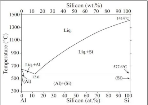
Figure 2.1 The binary equilibrium phase diagram of the Al-Si alloy system. ... 12
Figure 2.2 Diagram representing precipitation stages with aging time. ... 15
Figure 2.3 Schematic of the T6 heat treatment process. ... 24
Figure 2.4 Schematic phase diagram of a heat-treatable alloy, showing temperature ranges for solutionizing and for aging and showing amount of solute precipitated during aging. ... 26
Figure 2.5 Comparison of the silicon morphology in: (a) unmodified and (b) Sr-modified (300 ppm Sr), near-eutectic aluminum-silicon alloys. ... 31
Figure 2.6 α-Fe and β-Fe intermetallic phases precipitated in Al 354 alloys. ... 32
Figure 2.7 Stress-strain curve. ... 33
Figure 2.8 Schematic diagram showing brittle vs ductile stress-strain behavior . ... 37
Figure 2.9 Photographs showing (a) ductile vs (b) brittle specimens. ... 37
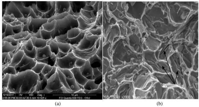
Figure 2.10 SEM images showing (a) a ductile fracture surface exhibiting a dimpled structure, and (b) a brittle fracture surface, showing how fracture occurs through the cracking of particles (arrowed). ... 39
Figure 2.11 Example of the quality chart proposed by Drouzy et al. [115] with iso-Q and iso-YS lines generated using Equations 1 and 2. ... 41
CHAPTER 3
Figure 3.1 Electrical resistance furnace. ... 45Figure 3.2 Graphite degassing impeller. ... 45
Figure 3.3 ASTM B-108 permanent mold used for casting tensile test bars. ... 46
Figure 3.4 Dimensions of the tensile test bar (in mm). ... 46
Figure 3.5 Lindberg Blue M electric furnace. ... 48
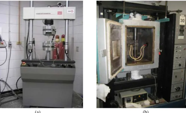
Figure 3.6 (a) MTS mechanical testing machine for room temperature testing, and (b) Instron Universal mechanical testing machine for high temperature testing. ... 51
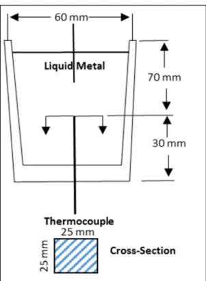
Figure 3.7 Schematic drawing showing the graphite mold used for thermal analysis. ... 53
Figure 3.8 Thermal analysis set-up. ... 53
Figure 3.9 Diagram showing the sectioned area for analysis of tensile samples using optical microscopy. ... 54
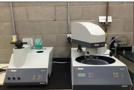
Figure 3.10 Struers LaboPress-3 and TegraForce-5 machines for mounting and polishing of metallography samples. ... 55
Figure 3.11 Clemex Vision PE 4.0 image analyzer-optical microscope system. ... 56
Figure 3.12 Scanning electron microscope system used in this study. ... 57
Figure 3.13 Field emission scanning electron microscope used in this study. ... 57
CHAPTER 4
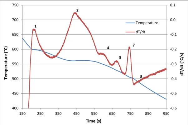
Figure 4.1 Temperature-time plot and first derivative obtained from the thermal analysis of Alloy R (354 + 0.25% Zr). ... 62Figure 4.2 Optical microstructure of R (354 + 0.25% Zr) alloy sample obtained from the thermal analysis casting (cooling rate 0.35°C/s), showing the different phases present in the alloy: 1- Al2Cu; 2- AlMgCuSi; 3- AlZrTi. ... 62
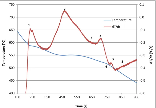
Figure 4.3 Temperature-time plot and first derivative from the thermal analysis of Alloy S (354 + 2% Ni + 0.25% Zr). ... 63 Figure 4.4 Optical microstructure of Alloy S (354 + 2% Ni + 0.25% Zr) sample obtained
from the corresponding thermal analysis casting (cooling rate 0.35°C/s), showing the different phases present in the alloy: 2- AlCuNi; 3- AlNiFe; 3a- AlSiNiZr-Fe; 4- Al2Cu. ... 64
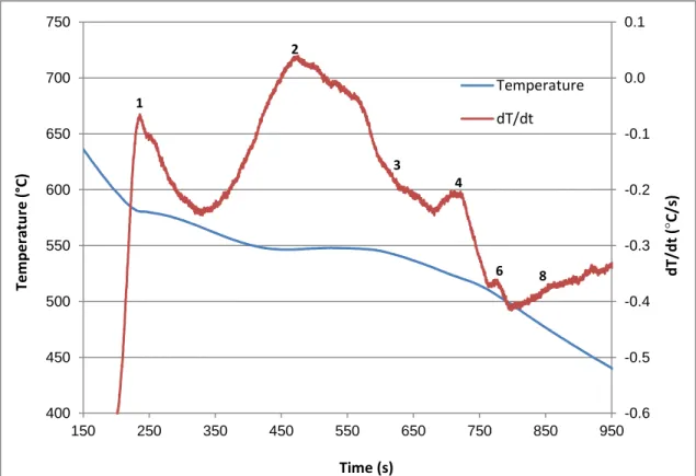
Figure 4.5 Temperature-time plot and first derivative from the thermal analysis of Alloy T (354 + 4% Ni + 0.25% Zr). ... 65 Figure 4.6 Optical microstructure of Alloy T (354 + 4% Ni + 0.25% Zr) sample obtained
from the corresponding thermal analysis casting (cooling rate 0.35°C/s), showing the different phases present in the alloy: 1-AlCuNi; 2- AlNiFe; 3- AlTiZr; 4- β-AlFeSi; 5- Al2Cu. ... 66
Figure 4.7 Temperature-time plot and first derivative from the thermal analysis of Alloy U (354 + 0.75% Mn + 0.25% Zr). ... 67 Figure 4.8 Optical microstructure of Alloy U (354 + 0.75% Mn + 0.25% Zr) sample
obtained from the thermal analysis casting (cooling rate 0.35°C/s), showing the different phases present in the alloy: 2- Al2Cu; 3- AlSiMnFe. ... 68
Figure 4.9 Temperature-time plot and first derivative from the thermal analysis of Alloy V (354 + 0.75% Mn + 2% Ni + 0.25% Zr). ... 69 Figure 4.10 Optical microstructure of Alloy V (354 + 0.75% Mn + 2% Ni + 0.25% Zr)
sample obtained from the thermal analysis casting (cooling rate 0.35°C/s), showing the different phases present in the alloy: 2- AlNiCu; 3- AlFeNiCu; 4- Al2Cu; 5- Zr-rich phase. ... 70
Figure 4.11 Temperature-time plot and first derivative from the thermal analysis of Alloy Z (354 + 0.15% Sc + 0.25% Zr). ... 71 Figure 4.12 Optical microstructure of Alloy Z (354 + 0.15% Sc + 0.25% Zr) sample,
obtained from the thermal analysis casting (cooling rate 0.35°C/s), showing the different phases present in the alloy: 1- (Al,Ti)(Sc,Zr); 2- Al2Cu; 4- β-AlFeSi;
5- (Al,Si)(Sc,Zr,Ti). ... 71 Figure 4.13 Temperature-time plot and first derivative from the thermal analysis of Alloy
L (398 + 0.15% Sc + 0.25% Zr). ... 73 Figure 4.14 Optical microstructure of Alloy L (398 + 0.15% Sc + 0.25% Zr) sample
obtained from the thermal analysis casting (cooling rate 0.35°C/s), showing the different phases present in the alloy: 1- Al2Cu; 2- β-AlFeSi; 3- (Al,Si)(Sc,Zr);
4- π-AlMgFeSi. ... 74 Figure 4.15 Optical micrographs of alloy R (354 + 0.25%Zr) showing the microstructures
Figure 4.16 Optical micrographs of Alloy S (354 + 0.25% Zr + 2% Ni) showing the microstructures observed in (a) as cast, (b) SHT–1 and (c) SHT–2 tensile test samples (500x). ... 81 Figure 4.17 Optical micrographs of Alloy T (354 + 0.25%Zr + 4%Ni) showing the
microstructures observed in (a) as cast, (b) SHT–1 and (c) SHT–2 tensile test samples (500x). ... 82 Figure 4.18 Optical micrographs of Alloy U (354 + 0.25%Zr + 0.75%Mn) showing the
microstructures observed in (a) as cast, (b) SHT–1 and (c) SHT–2 tensile test samples (500x). ... 84 Figure 4.19 Optical micrographs of Alloy V (354 + 0.25%Zr + 0.75%Mn + 2%Ni)
showing the microstructures observed in (a) as cast, (b) SHT–1 and (c) SHT–2 tensile test samples (500x). ... 85 Figure 4.20 Optical micrographs of Alloy Z (354 + 0.25%Zr + 0.15%Sc) showing the
microstructures observed in (a) as cast, (b) SHT–1 and (c) SHT–2 tensile test samples (500x). ... 87 Figure 4.21 Optical micrographs of Alloy L (398 + 0.25%Zr + 0.15%Sc) showing the
microstructures observed in (a, b) as cast, (c) SHT–1 and (d) SHT–2 tensile test samples at 500X magnification. Circled areas in (c) and (d) highlight
dissolution of phases. ... 89
CHAPTER 5
Figure 5.1 Mean values for UTS, YS, % El for Alloys R, S, T, U and V in the as-cast and SHT 1 and SHT 2 solution heat-treated conditions. ... 95 Figure 5.2 Quality chart showing relationship between UTS and percent elongation for the
354 alloys investigated in the as-cast and SHT 1 and SHT 2 solution heat treated conditions. ... 96 Figure 5.3 Mean values for UTS, YS, % El for Alloys R, S, T, U and V obtained under the given heat treatment conditions (without stabilization). ... 100 Figure 5.4 Mean values of UTS, YS, % El for Alloys R, S, T, U and V obtained under the
given heat treatment conditions (after 200 hours stabilization at 250°C). ... 101 Figure 5.5 Quality index-color contour charts for Alloys R, S, T, U and V obtained from
room temperature tensile testing data: (a) without stabilization, and (b) after 200 h stabilization at 250°C ... 105 Figure 5.6 Probable yield strength-color contour charts for Alloys R, S, T, U and V
obtained from room temperature tensile testing data: (a) without stabilization, and (b) after 200 h stabilization at 250°C. ... 107 Figure 5.7 Mean values for UTS, YS, % El for Alloy R at the given heat treatment
condition: (a) without, and (b) after 200 h stabilization at 250°C prior to testing. ... 110 Figure 5.8 Mean values for UTS, YS, % El for Alloy S at the given heat treatment
condition: (a) without, and (b) after 200 h stabilization at 250°C prior to testing. ... 113
Figure 5.9 Mean values for UTS, YS, % El for Alloy U at the given heat treatment condition: (a) without, and (b) after 200 h stabilization at 250°C prior to testing. ... 115 Figure 5.10 Quality charts showing UTS vs % El plots for Alloys R, S and U subjected to
various heat treatment conditions, and tested at room temperature without and with 200 h stabilization at 250°C prior testing. ... 117 Figure 5.11 Comparison of tensile test data of Alloys R, S, U, Z and Alloy L listed in Table
5.4 (Room temperature tensile testing). ... 121 Figure 5.12 Comparison of tensile properties of R, S and U alloys relative to those of
as-cast base alloy R: (a) UTS, (b) YS, and (c) %El without, and after 200h
stabilization at 250°C. ... 125 Figure 5.13 Mean values for UTS, YS, % El for alloy R at the given heat treatment
conditions for; (a) One and (b) 200 hours stabilization at 250°C. ... 128 Figure 5.14 Mean values for UTS, YS, % El for alloy S at the given heat treatment
conditions for; (a) One and (b) 200 hours stabilization at 250°C. ... 130 Figure 5.15 Mean values for UTS, YS, % El for alloy U at the given heat treatment
conditions for; (a) One and (b) 200 hours stabilization at 250°C. ... 132 Figure 5.16 Quality charts showing UTS vs % El plots for Alloys R, S and U subjected to
various heat treatment conditions (testing at 250°C after 1h stabilization). ... 135 Figure 5.17 Quality charts showing UTS vs % El plots for Alloys R, S and U subjected to
various heat treatment conditions (testing at 250°C after 200h stabilization). ... 136 Figure 5.18 Relevant part of Figure 5.17 rescaled to distinguish the contour lines obtained
for Alloys R, S and U. ... 137 Figure 5.19 Comparison of tensile test data of Alloys R, S, U, Z and Alloy L listed in Table
5.5 (tested at 250°C after 1 h stabilization)... 141 Figure 5.20 Comparison of tensile test data of Alloys R, S, U, Z and Alloy L listed in Table
5.6 (tested at 250°C after 200 h stabilization)... 142 Figure 5.21 Comparison of the precipitates observed in Alloy U tested at 250 °C, after (a) 1
hr, and (b) 200 hrs stabilization at testing temperature. ... 145 Figure 5.22 Quality charts showing UTS vs %El plots for Alloys R, S, U, Z and L in the
as-cast and T6-heat treated conditions (testing at 250°C after 1 h stabilization at testing temperature). ... 147 Figure 5.23 Quality charts showing UTS vs %El plots for Alloys R, S, U, Z and L in the
as-cast and T6 heat-treated conditions (testing at 250°C after 200 h
stabilization at testing temperature). ... 148 Figure 5.24 Comparison of high temperature tensile properties of R, S and U alloys relative
to those of the as-cast base alloy: (a) UTS, (b) YS, and (c) %El after 1 h and 200 h stabilization at 250°C. ... 152
LIST OF TABLES
CHAPTER 2
Table 2.1 Cast aluminum alloy designation. ... 11 Table 2.2 Common aluminum heat treatment designations ... 29 CHAPTER 3
Table 3.1 Chemical composition of the as-received 354 alloy ... 45 Table 3.2 Chemical composition of the alloys used in this study. ... 47 Table 3.3 Summary of the heat treatment and testing conditions at room and high
temperatures ... 49 CHAPTER 4
Table 4.1 Suggested main reactions occurring during solidification of 354-type alloys .... 60 Table 4.2 Porosity measurements for Alloys R, S, T, U, V, Z and L. ... 76 CHAPTER 5
Table 5.1 Mean values for UTS, YS, %El for alloys R, S, T, U, V, Z and L subjected to different heat treatment conditions and tested at ambient temperature; Q values obtained using Equation 1 ... 94 Table 5.2 Mean values of UTS, YS, %El obtained at room temperature (without
stabilization) for Alloys R, S, T, U and V subjected to different heat treatment conditions; Q and Probable YS values were obtained using Eqns 1 and 2 ... 98 Table 5.3 Mean values of UTS, YS, %El obtained at room temperature (after 200h/250°C
stabilization) for Alloys R, S, T, U and V subjected to different heat treatment conditions; Q and Probable YS values were obtained using Eqns 1 and 2 ... 99 Table 5.4 Comparison of tensile properties of Alloys R, S, U, Z and L (tested at room
temperature without stabilization) ... 120 Table 5.5 Comparison of high temperature tensile properties of Alloys R, S, U, Z and L
(tested at 250°C after 1 h stabilization at testing temperature) ... 139 Table 5.6 Comparison of high temperature tensile properties of Alloys R, S, U, Z and L
(tested at 250°C after 200 h stabilization at testing temperature). ... 140 Table 5.7 High temperature tensile properties of reference alloy R, (tested at 250°C after 1
1
CHAPTER 1
CHAPTER 1
DEFINING THE PROBLEM
1.1
INTRODUCTION
Aluminum is one of the most versatile of the common foundry metals, with cast products consuming, as a world average, ~20% of this metal. Apart from the light weight, the special advantages of aluminum alloys for castings are their relatively low melting temperatures, negligible solubility for all gases except hydrogen, and the good surface finish that is usually achieved with the final products. Most alloys also display good fluidity and compositions can be selected with solidification ranges appropriate to particular applications.
The first casting alloy used in America was an Al-8% Cu composition, known as No. 12 alloy. An Al-10% Cu alloy (No. 122) was used for automotive pistons and cylinder heads. In 1909, Alfred Wilm discovered that an Al-4.5%Cu-0.5%Mn alloy would strengthen by aging, after a quench from an elevated temperature. This alloy was called “Duralumin” and formed the basis for the Al-Cu family of alloys used today. The Al-Cu alloys have excellent mechanical properties; but they are difficult to cast primarily because of hot cracking. As the years went by, foundrymen discovered that additions of other elements, especially silicon, improved alloy castability. For this reason, cast Al-Cu alloys have been largely supplanted by cast Al-Cu-Si and Al-Si alloys [1].
During the past few decades, the automotive industry has shown a great interest in aluminum for its applications. Today aluminum is an essential material in car manufacturing and its alloys are actually used in the components of cylinder blocks, pistons and other engine parts. It is believed that 1 kg of aluminum can replace up to 2 kg of steel and cast iron in many areas of application [2]. The more aluminum alloys are used in the production of a vehicle, the less the weight of the vehicle is, and the less fuel it will consume, thereby reducing the amount of harmful emissions into the atmosphere. Actually, as an industry, scientific researches must follow the needs of the designers. So they are required to be at the same point of thinking with the designers, and to appreciate the boundary conditions and constraints of their work. Secondly, the casting industry should have the means and tools to tailor and optimize alloys for specific performance/applications. As pointed out above, developing alloys for specific processes is not the norm, although it should be taken into consideration. Therefore, it is important to optimize the performance attained from specific processes by ensuring that the alloys processed are optimized to take advantage of the merits of the particular process.
Today, we have predictive tools that enable us to work in a much more intelligent and effective way than in years past. The trial and error approach of alloy development is not only ineffective but also economically unsustainable. Cast components undergo post-processing operations, such as heat-treating, etc. In complex alloys, the range of elemental composition may make all the difference during heat-treating. Predictive tools mitigate, if not prevent, the occurrence of incidences such as incipient melting. So it is not only during the alloy and processing stages that these enabling tools are useful, but also during post-processing operations.
For aluminum alloys, the principle alloying elements, in addition to silicon (Si), are magnesium (Mg) and copper (Cu). However, most Al-Si alloys are not suitable for high temperature applications because their tensile and fatigue strengths are not as high as desired in the temperature range 230-350°C, a range often observed under service conditions. Most of the Al-Si cast alloys to date are intended for applications at temperatures no higher than about 230°C; however, some interesting improvements have been achieved by modifying the composition of the base alloy with the addition of Mn and Ni, resulting in an increase in strength and ductility at both room and high temperatures. Thus, there is a need in the automobile industry for developing a low-cost, high strength aluminum alloy, exhibiting high wear resistance and a low coefficient of thermal expansion, with better tensile and fatigue strength at temperatures of 260-370°C.
Iron is traditionally considered as a harmful element in Al–Si alloys since platelets of the coarse and brittle lamellar β-iron Al5FeSi may be formed as a primary phase, when
the iron content is more than 0.5 wt.% [3]. It is found that the α-iron Al15(Fe, Mn)3Si2
phase can be formed, instead, if both Fe and Mn are added under certain solidification rates [4]. Due to its Chinese script morphology, a certain amount of such α-Fe phase particles indeed improve the tensile strength and retard the extension of micro-cracks during tensile testing [3].
Zirconium has a low solubility in aluminum, and only small additions of Zr are therefore necessary to form dispersoids. In many alloys, however, Al3Zr is heterogeneously
distributed, and in the areas where the number density of dispersoids is low, the alloy will be prone to recrystallization [5]. The addition of transition elements such as Ni and Cu is considered to be an effective way to improve the high temperature strength of cast Al-Si
alloys in as-cast and solution-treated conditions through the formation of stable aluminides. Copper and magnesium as alloying elements are often added to improve alloy strength at room temperature as well as at higher temperatures [6].
Hypoeutectic Al-Si-Cu-Mg alloys exhibit three main solidification reactions during the solidification process, starting with the formation of α-Al dendrites followed by the development of two main eutectic phases; eutectic silicon and secondary β-(Al, Si, Fe) phase. The presence of alloying and impurity elements such as Cu, Mg, Mn, Fe leads to more complex constituents, including intermetallic phases, that may be characterized by metallographic techniques [7].
Heat-treatment is of major importance since it is commonly used to alter the mechanical properties of cast aluminum alloys. Heat treatment improves the strength of aluminum alloys through a process known as precipitation hardening, which occurs during the heating and cooling of an aluminum alloy, and in which precipitates are formed in the aluminum matrix. The improvement in the mechanical properties of Al alloys as a result of heat treatment depends upon the change in solubility of the alloying constituents with temperature [8].
A comprehensive study was carried out to investigate the effect of additions of Zr, Ni, Mn and Sc on the microstructure and tensile properties of Al-Si-Cu-Mg 354 type alloys at ambient and high temperatures. Generally, the mechanical properties and microstructure of aluminum cast alloys are dependent on the composition, the melt treatment conditions, the solidification rate, the casting process and the applied thermal treatment. All these parameters were investigated in this study and the results obtained were analyzed in terms
of their effect on the microstructures and, hence, on the mechanical properties obtained for the 354 alloys.
1.2
OBJECTIVES
The current study was carried out to analyze the effect of Ni, Mn, Zr and Sc additions on the strength of cast aluminum alloy 354 (Al-9%Si-1.8%Cu-0.5%Mg), as well as the effect of only Zr and Sc additions on the strength of cast aluminum alloy 398 (Al-16%Si), at room and high temperatures for different holding times. The latter alloy was examined solely for the purpose of comparing how the properties of the 354 alloys investigated in this study stand with respect to the 398 alloy, an alloy developed by NASA and reported to give superior high temperature properties [9].
The evolution of the microstructural features with the addition of the above alloying elements and their consequent effect on the mechanical properties were investigated. Based on this approach, the principal objectives of this study cover the following.
I. Examining the main microstructural features observed in the alloys, such as phases, intermetallics, and precipitates, together with their identifying characteristics and evolution during controlled exposure at different temperatures and times.
II. Determining the room temperature tensile properties of the alloys subjected to different aging conditions (temperature and time).
III. Obtaining the high temperature tensile property values at different temperatures for selected alloys or conditions based on the room temperature tensile testing results.
IV. Correlating the results obtained from the room temperature and high temperature tensile tests with the principal microstructural features observed in the corresponding alloy samples, in order to analyze and understand the major parameters involved in the strengthening of alloy 354 at high temperatures.
V. Determining the effect of Zr and Sc as alloying element additions on the mechanical properties of high-strength cast aluminum alloy 398 (Al-16%Si) and comparing the properties obtained with those of 354 aluminum alloy.
1.3
THESIS LAYOUT
The structure of this thesis is presented in five chapters. Chapter 1 introduces the research study which was carried out and defines its objectives. Chapter 2 presents the literature review about the topic of this thesis. Chapter 3 describes the experimental procedures and testing methods which were employed in the given research. Details of the microstructural examination of the alloys investigated, identification and qualitative and quantitative analyses are provided in Chapter 4. Chapter 5 presents the room and high-temperature mechanical properties of the alloys. The results are discussed and analyzed in terms of the microstructural data presented in Chapter 4. Chapter 6 presents conclusions, followed by recommendations for future work. A list of references is provided at the end.
2
CHAPTER 2
CHAPTER 2
LITERATURE SURVEY
2.1
INTRODUCTION
It is known that aluminum alloys are developed with allowance for the effect of each alloying element on the phase composition and structure from the standpoint of obtaining the desired result, for example, raising the alloy strength or ductility or its high-temperature performance. The alloying is used for providing the maximum possible number of structural mechanisms that can cause an increase in the requisite properties. The efficiency of alloying additions depends on the modifying and refining actions of the alloying elements. A special feature of the alloying process is the possibility of formation of new phases with a complex composition, which can influence the strength and ductility characteristics.
2.2
ALUMINUM CAST ALLOYS
Aluminum casting alloys find wide use in several applications employed in automotive, aerospace and other transportation industries [10-12]. Aluminum alloys have about one-third of the density and modulus of elasticity of steels, high thermal and electrical conductivity, high corrosion resistance [13], high friction coefficient, excellent formability, low melting point, high magnetic neutrality, and the possibility for a wide range of possible surface treatments [14,15]. The increasing demand for the use of aluminum alloys is related not only to their mechanical performance, economical
efficiency and environmental advantages, but also to the fact that these alloys offer advantageous safety features since the ability of aluminum to absorb the energy of impact in case of an accident is twice that of steel for the same weight.
The continuous and steady growth of aluminum alloy usage in industrial applications is directly related to the need for taking advantage of such specific assets as a high strength-to-weight ratio, and by so doing to enhance mechanical performance and to lessen energy consumption [16-18].
Aluminum alloys are classed into two groups, wrought alloys and cast alloys. Furthermore, depending on whether they contain hardening elements such as magnesium and copper, they are further distinguished as heat-treatable or non-heat treatable alloys. Heat-treatable alloys are those whose strength is improved after subjecting the alloy to heat treatment; whereas non-heat treatable alloys are strengthened through mechanical working or deformation, the strengthening process in the two cases being termed ‘precipitation hardening’ and ‘work hardening’, respectively.
The cast alloy designation system is based on a 3 digit-plus decimal designation xxx.x (i.e. 356.0). The first digit (Xxx.x) indicates the principal alloying element which has been added to the aluminum alloy (see Table 2). The second and third digits (xXX.x) are arbitrary numbers given to identify a specific alloy in the series. The number following the decimal point indicates whether the alloy is a casting (.0) or an ingot (.1 or .2). A capital letter prefix indicates a modification to a specific alloy [19].
Table 2.1 Cast aluminum alloy designation [19]. Alloy Series Principal alloying elements
1xx.x Commercially pure aluminum >99 % purity (non-heat treatable)
2xx.x Copper (heat treatable)
3xx.x Silicon plus Copper and/or Magnesium
4xx.x Silicon (non-heat treatable)
5xx.x Magnesium (non-heat treatable)
6xx.x Unused Series
7xx.x Zinc (heat treatable)
8xx.x Tin
9xx.x Other elements
2.3
ALUMINUM-SILICON CAST ALLOYS
Among the most commonly used cast aluminum alloys are those belonging to the Al-Si system. Due to their mechanical properties, excellent castability and corrosion resistance, these alloys are primarily used in engineering and in the automotive industry. Cast Al-Si alloys are divided into three categories: hypoeutectic alloys, with a Si concentration from 4 to 10 mass%, near-eutectic alloys with a Si concentration of 10-13 mass%, and hypereutectic alloys with a Si concentration of 17-26 mass %.
The eutectic–silicon morphology also has a considerable influence on the mechanical properties of these alloys. Acicular-shaped eutectic silicon particles normally observed in the as-cast alloy can be modified to fibrous or spherical ones by the addition of chemical modifiers such as strontium (Sr), sodium (Na) or antimony (Sb), in order to improve the alloy ductility and strength. Heat treatment, or thermal modification, can also
Binary cast aluminum-silicon alloys used in industrial practice contain silicon in a concentration close to the eutectic (10-13 mass% Si). These alloys have optimum cast properties due to eutectic crystallization at a constant temperature, which improves the castability of the molten metal and thus reduces the formation of shrinkage to approximately 1.15% during the casting process. Silicon has a beneficial influence in that it reduces the melting temperature of the aluminum alloy and improves its fluidity and promotes the formation of strengthening precipitates through the expected reaction of Si and Mg present in solid solution to form Mg2Si [22]. The higher tensile strength can also
be attributed to the presence of spheroidized particles of Si that provide substantial dispersion hardening [23].
In spite of these advantages, however, Al-Si alloys are limited to applications which can work up to temperatures of ~250 °C [6] as above this temperature, the alloys lose coherency between the aluminum solid solution matrix and the precipitated particles which will then rapidly coarsen and dissolve again into the solid solution, resulting in an alloy having an undesirable microstructure for high temperature applications [24].
2.3.1
Role of alloying elements in Al-Si alloys
Copper and magnesium are the main alloying elements added to Al-Si cast alloys for use in industrial applications. Addition of these elements increases the alloy strength after aging because of the precipitation of different hardening phases such as θ′ (Al2Cu), S′
(Al2CuMg) and β″ (Mg2Si) [25]. The Mg content of commercial 354 alloys ranges from
0.4 to 0.7 wt%. The addition of Mg results in the formation of the Q-Al5Mg8Si6Cu2 phase
which grows from the blocky Al2Cu phase during the last stage of solidification. The
coarseness of the Q phase increases with increasing Mg content [26]. In applications where ductility is not the most important factor in material selection, adding Cu to these alloys has the distinct advantage of increased strength at high temperatures. However, the addition of Cu also decreases the solidus eutectic temperatures of the alloy, thereby increasing the solidification range of the alloy, resulting in a tendency to develop porosity and hot cracking [27].
2.3.1.1 Al-Si-Cu alloys
Adding copper to an Al-Si alloy increases its strength and facilitates precipitation hardening but it reduces ductility and corrosion resistance [28]. When the Cu content is above its solubility in Al, the precipitation of the second phase θ' (Al2Cu) also contributes
aluminum matrix despite the short duration employed; this element is critical in facilitating age hardening, particularly when Mg and Si are also present [29].
In an Al-Cu alloy, upon appropriate heat treatment, the Cu atoms progressively cluster together to form very small particles which separate out within the matrix grains of the alloy; this process is called precipitation [30]. The strengthening effect of Cu in Al-Si alloys is linked to the precipitation of the secondary eutectic phases of intermetallic Al2Cu
or Al5Cu2Mg8Si6 that form upon aging during the T6 heat treatment. A solution
temperature that exceeds the solidus temperature of incipient melting leads to the occurrence of incipient melting of the Cu-rich phases, which would deteriorate the mechanical properties of these alloys [31, 32].
The alloy is initially in a state far from equilibrium and, given sufficient time at the applied temperature, diffusion of atoms occurs progressively to transform the metallurgical structure towards the equilibrium state. The precipitation process creates precipitate particles that usually provide an appreciable hindrance to plastic deformation by slip. Hence, as precipitation progresses and the size and amount of precipitates increases, the alloy hardens and strengthens with time. The full precipitation occurs only when the alloy is artificially aged at temperatures below the solvus of the Guinier Preston 1 (or GP1) zone.
Many steps in this process may be covered up by aging at temperatures above the Guinier Preston zones, θ' and θ", simultaneously with the solvus line of the stable phase θ [33, 34]. The primary hardening at 180 °C is added to GP1 zones. After attaining a critical radius of 5 nm, an incubation time starts, during incubation period the size of the zone and the value of hardness remains unchanged [35, 36].
Figure 2.2 Diagram representing precipitation stages with aging time [37].
A content of approximately 1% of copper provides good mechanical properties at high temperature, without significantly affecting the elongation at room temperature [38]. The addition of transition elements such as Cu in addition to Ni is considered to be effective for increasing the room and the high temperature strength of cast Al-Si alloys by forming stable aluminides [39]. As with the as-cast condition, ductility for alloys aged to a T6 temper decreases gradually as the Cu content is raised [22].
2.3.1.2 Al-Si-Mg alloys
Al-Si-Mg alloys are also of great interest in the transportation field due to their high specific strength and good castability. Magnesium provides substantial strengthening and improvement of the work-hardening characteristics of aluminum. It has a relatively high solubility in solid aluminum, and has a major impact on strengthening while decreasing the ductility, as reported by Caceres et al. [40]. In general, corrosion resistance and weldability are also good [41].
When present in combination with Cu and/or Si, Mg is also a very efficient alloying addition for strengthening aluminum alloys. Even small amounts of Mg can have a
profound effect on age hardening [22]. Tavitas-Medrano et al. [42] have reported that additions of 0.4 wt% Mg increase the response of the alloy to artificial aging, thereby increasing the tensile strength and micro-hardness values achievable, however, at the expense of reduced elongation and impact toughness.
Magnesium is added to Al-Si alloys to make them heat treatable whereby, through the formation of Mg2Si precipitates upon aging, the alloy strength is increased via
precipitation hardening. The microstructure of as-cast hypoeutectic aluminum alloys, however, contains coarse primary α-Al dendrites and acicular shaped eutectic silicon particles, which reduce the mechanical properties [43, 44]. With heat treatment, the mechanical properties of Al-Si-Mg alloys can be improved noticeably.
The mechanical properties of heat-treatable cast Al-Si-Mg alloys, such as the A356 alloy, are negatively affected by prolonged exposure at high temperatures [45, 46]. A significant reduction in hardness and tensile strength already occurs at temperatures equal to or higher than 200 °C, thus limiting the application of these alloys in the case of automotive and other engine components.
With the aim of overcoming these limits and ensuring a superior thermal stability, Al-Si-Cu-Mg alloys are currently under extensive study [8, 47-49]. In particular, the alloys being developed are expected to have superior thermal stability in comparison to the widely used A356 and A357 (Al-Si-Mg) casting alloys, thanks to the presence of more stable Cu-based intermetallic precipitates, as observed in Al-Mg-Si-Cu alloys [50]. Al-Si-Mg and Al-Si-Cu alloys are characterized, respectively, by the strengthening phases Al-Si-Mg2Si
and Al2Cu, whose precipitation sequences were studied in Al-Mg-Si and Al-Cu alloys
α (SSS)→GP zones→ β”→ β’/B’→ β in Al-Mg-Si alloys, and
α (SSS)→GP zones→ θ”→ θ’→ θ in Al-Cu alloys,
where β”,β’, B’ and θ”, θ’ are the intermediate coherent/semi-coherent precipitates, while β and θ are the stable incoherent phases.
In quaternary Al-Si-Cu-Mg alloys, the presence of both Cu and Mg induces the formation of further reinforcing compounds, such as the S phase, characterized by the stoichiometry Al2CuMg, according to the following precipitation sequence [56, 57]:
α (SSS)→GPB zones→ S”→ S’→ S
After the decomposition of the supersaturated solid solution (SSS), the formation of Guinier–Preston–Bagaryatsky (GPB) zones occurs, followed by the precipitation of the coherent S”, semi-coherent S’ , and incoherent equilibrium S phase. The quaternary Q phase (AlCuMgSi) was also observed in Al-Cu-Mg-Si alloys, characterized by a complex precipitation sequence, depending on alloy composition [58, 59], which may be expressed by:
α (SSS)→QP→ QC→ Q’→ Q
where QP, QC and Q’ are the precursors of the stable Q phase. The Cu-containing phases should confer to the quaternary Al-Si-Cu-Mg alloys a superior thermal stability in comparison to the more widely used Al-Si-Mg alloys, leading to a better response of the T6 heat-treated alloys to high temperature exposure (i.e., overaging) [50].
2.4
EFFECT OF ALLOYING ELEMENTS ON Al-Si ALLOYS
Alloying elements are usually added to Al–Si cast alloys in order to improve microstructure features and thus improve mechanical properties. Nickel (Ni) and Zirconium (Zr) are used as alloying additions to increase high temperature strength in aluminum alloys due to the production of the L12-type precipitates Al3Zr or Al3Ni, which
are more able to maintain overaging at higher temperatures than the precipitates existing in cast aluminum alloys such as Al2Cu and Mg2Si [60]. Manganese (Mn) is used to neutralize
the effect of iron (Fe) and to modify the morphology and type of intermetallic phases formed. Scandium (Sc) in aluminum alloys acts as an effective grain refiner and increases the recrystallization temperature, the corrosion resistance, and weldability.
2.4.1
Zirconium (Zr)
Zirconium is added to aluminum to form fine precipitates of intermetallic particles
that inhibit recrystallization [6]. For alloys with zirconium additions, a non-recrystallized structure can be obtained after heat treatment which provides a high level of structural
hardening for a wider range of semi-products than in the case of aluminum alloys
containing manganese (Mn). These products include virtually all pressed and rolled plates,
stampings, forgings, and some cold-deformed semi-products (sheets) obtained from
Al-Zn-Mg and Al-Zn-Al-Zn-Mg-Cu alloys, which require a lower temperature of heating for hardening
Zirconium is usually present in aluminum alloys in an amount ranging from 0.1 to
0.25%. Segregations of the Al3Zr phase particles formed are finer than those of Mn
aluminides (10-100 nm in size) [61]. However, the effect of precipitation hardening due to
segregation of the Al3Zr phase is not high because of the low content of Zr in the alloys
similar to the case of the Mn aluminides, although the effect of the finer zirconium
aluminide segregates on the process of recrystallization in deformed semi-products and,
accordingly, on their grain structure, is considerably stronger [5]. Additionally, it has been
shown that Zr increases the resistance to overaging when it is added to binary Al-Sc alloys
[62].
2.4.2
Nickel (Ni)
Cast Al-Si alloys usually contain alloying components such as magnesium, copper, nickel, etc. which are widely used in the automotive industry in piston applications [63,64]. These additions form intermetallic phases with complex morphologies and complex compositions. Nickel is added to Al-Cu and Al-Si alloys to improve hardness and strength at elevated temperatures and to reduce the coefficient of thermal expansion, as there is an increasing demand for Al-Si cast alloys with better performance concerning yield and tensile strength at elevated temperatures up to 250 °C [65]. In fact, the addition of alloying elements such as Cu and Ni is an effective and practical way to improve the mechanical properties, especially in relation to the performance of piston alloys which are subjected to high temperature service conditions [66].
The advantages of adding Ni and Zr to Al-Si alloys are that their precipitates (Al3Ni
and Al3Zr) possess the following important characteristics:
• They are coherent; • Possess low solubility;
• Directly affect the strength of the material because they act as hard pinning points
which inhibit the movement of dislocations in the matrix.
2.4.3
Manganese (Mn)
Manganese is very soluble in aluminum; when the cast is chilled, most of the added manganese is substantially retained in solution. It increases the strength of the alloy either in solid solution or as a finely precipitated intermetallic phase by modifying the morphology of the intermetallic phases which are formed after heat treatment of the given alloy. As reported by Seifeddine et al. [67], it has no adverse effect on corrosion resistance. Manganese combines with Fe in the alloy forming the script-like α-iron phase which is more compact and less detrimental to the mechanical properties [68]. Hwang et al. [69] have reported that as the Mn content is increased up to 0.65 wt% corresponding to an Fe/Mn ratio of 1.2 in the Al-7wt.% Si-3.8 wt.% Cu-0.5 wt.% Fe alloy, the plate-like β-Al5FeSi iron intermetallic phase is completely converted to the Chinese script
α-Al(Fe,Mn)Si iron phase, resulting in improved tensile properties. Excess amounts of Mn, however, deteriorate the mechanical properties by increasing the total amount of iron-containing intermetallic phases formed.
2.4.4
Scandium (Sc)
Al-Sc alloys have excellent mechanical properties at ambient and elevated temperatures due to the presence of a high density (as high as 1022 m-3) of elastically-hard L12 type Al3Sc precipitates which remain coherent with the α-Al matrix at elevated
temperatures [70, 71]. Krug [72], and Seidman and coworkers [73, 74] have reported that the Al3Sc precipitates coarsen slowly up to ~300oC, imparting good creep resistance in
coarse-grained cast alloys. The low lattice parameter mismatch of Al and Al3Sc also
contributes to the high creep resistance of Al-Sc alloys. The good interfacial strength between the Al3Sc precipitates and the aluminium matrix creates a significant lattice strain,
which blocks dislocation motion and prevents grain growth [75]. Furthermore, the thermal stability of the Al3Sc precipitates suppresses recrystallization [76] and leads to a significant
strengthening effect. Although Al-Sc alloys appear to be very promising alloys for high temperature applications, their application is limited by the high cost and availability of Sc.
A possible solution to this problem would be to achieve solid solution strengthening using substitute alloying additions that are similar in nature to Sc, to reduce the Sc content without lowering the properties. Kending [77], and Dunand and coworkers [78-82] showed that ternary additions to Al-Sc alloys improve mechanical properties by solid solution strengthening as in the case of Mg, or by substituting for Sc in Al3Sc
precipitates as in the cases of Ti and Zr.
Scandium (Sc) addition to Al alloys results in as-cast grain size refinement, an increase in mechanical properties and improvement of weldability [83]. It acts as an effective grain refiner and increases the recrystallization temperature so that it does not form any second phase intermetallic compounds with other alloying elements such as Fe,
Mg, Mn and Si [84]. While the addition of Sc to Al alloys is more effective in improving resistance to recrystallization than Zr [85]due to the formation of a high density of Al3Sc
particles, the addition of both Sc and Zr produces Al3(Sc,Zr) particles which are more
stable than the Al3Sc dispersoids, thus increasing the resistance to recrystallization [86,87];
however, Sc is too expensive to be extensively used in industry [88], so cheaper rare-earth element additions are being studied to replace it.
2.4.5
Strontium (Sr)
As mentioned previously, the eutectic silicon morphology has a considerable influence on the mechanical properties of Al-Si based alloys. The tips of the needle-like eutectic silicon particles in an unmodified Al-Si alloy act as stress raisers which are harmful to the mechanical properties. Acicular-shape eutectic silicon particles normally observed in the as-cast alloy can be modified to fibrous or spherical ones by the addition of chemical modifiers. The most common element used in industry today is strontium (Sr) [89], which is added in the form of Al-Sr master alloy to Al-Si alloy melts in order to
change or ‘modify’ the morphology of the eutectic silicon particles from their normally brittle, acicular form to a fibrous form during solidification. Both Sr addition and solidification rate have a strong influence on the microstructure. The change in morphology from acicular to fibrous form results in improving the ductility of the alloy as well as its strength. [90]. According to Merlin and Garagnani [91], one of the disadvantages of modification, however, is that the addition of strontium to the alloy could increase the hydrogen content and, as a result, the presence of gas porosities.
![Figure 2.8 Schematic diagram showing brittle vs ductile stress-strain behavior [111].](https://thumb-eu.123doks.com/thumbv2/123doknet/7555479.229426/54.918.278.681.106.509/figure-schematic-diagram-showing-brittle-ductile-stress-behavior.webp)