Science Arts & Métiers (SAM)
is an open access repository that collects the work of Arts et Métiers Institute of
Technology researchers and makes it freely available over the web where possible.
This is an author-deposited version published in:
https://sam.ensam.eu
Handle ID: .
http://hdl.handle.net/10985/12461
To cite this version :
Nikola KALENTICS, Eric BOILLAT, Patrice PEYRE, Cyril GORNY, Christoph KENEL, Christian
LEINENBACH, Jamasp JHABVALA, Roland E. LOGÉ - 3D Laser Shock Peening – A new method
for the 3D control of residual stresses in Selective Laser Melting - Materials and Design - Vol. 130,
p.350-356 - 2017
Any correspondence concerning this service should be sent to the repository
Administrator :
archiveouverte@ensam.eu
3D Laser Shock Peening
– A new method for the 3D control of residual
stresses in Selective Laser Melting
Nikola Kalentics
a,⁎, Eric Boillat
a, Patrice Peyre
b, Cyril Gorny
b, Christoph Kenel
c,
Christian Leinenbach
c, Jamasp Jhabvala
a, Roland E. Logé
aaThermomechanical Metallurgy Laboratory– PX Group Chair, Ecole Polytechnique Fédérale de Lausanne (EPFL), CH-2002 Neuchâtel, Switzerland bProcesses and Engineering in Mechanics and Materials Laboratory (PIMM), CNRS-ENSAM Paristech, 151 Bd de l'Hôpital, 75013 Paris, France cEmpa-Swiss Federal Laboratories for Materials Science and Technology, Dübendorf, Switzerland
Keywords:
3D Laser Shock Peening Selective laser melting Laser Shock Peening Residual stress profile Fatigue life 316L stainless steel
A B S T R A C T
This paper describes a hybrid additive manufacturing process– 3D Laser Shock Peening (3D LSP), based on the integration of Laser Shock Peening (LSP) with selective laser melting (SLM). The well-known tensile residual stresses (TRS) in the as– built (AB) state of SLM parts in the subsurface region have a detrimental effect on their fatigue life. LSP is a relatively expensive surface post treatment method, known to generate deep CRS into the subsurface of the part, and used for high end applications (e.g. aerospace, nuclear) where fatigue life is crucial. The novel proposed 3D LSP process takes advantage of the possibility to repeatedly interrupt the part manufacturing, with cycles of a few SLM layers. This approach leads to higher and deeper CRS in the subsurface of the produced part, with expected improved fatigue properties. In this paper, 316L stainless steel samples were 3D LSP processed using a decoupled approach, i.e. by moving back and forth the baseplate from an SLM machine to an LSP station. A clear and significant increase in the magnitude and depth of CRS was observed, for all investigated process parameters, when compared to the AB SLM parts, or those traditionally LSP (surface) treated.
G R A P H I C A L A B S T R A C T
1. Introduction
Selective laser melting (SLM) is a part of a large family of Additive Manufacturing (also known as 3D printing) processes[1–3], and also
the most studied over the past years. In the SLM process the part is built layer by layer out of a metallic, ceramic, polymer or composite powder. At each step, a powder bed is deposited on a substrate and selectively melted by a laser beam. Using a laser beam deflection system, each ⁎Corresponding author.
E-mail address:nikola.kalentics@epfl.ch(N. Kalentics).
layer is scanned according to the corresponding part cross section, as calculated from the CAD (computer-aided design) model. After selective consolidation, a new powder layer is deposited, and the operation sequence is repeated until completion of the part. At the end, the unused powder is removed and can be reused in another building process. This manufacturing method leads to the ability to produce parts with high added value and very complex geometries, which would otherwise be difficult or impossible to produce. Typical examples concern lattice structures used for aerospace and medical applications, bionic design for weight reduction, conformal cooling channels in molds, etc.
Although the mechanical properties of parts made by SLM have become close to those produced by conventional processes[3–13], SLM still has several inherent limitations, one of them being the accumula-tion of detrimental tensile residual stresses (TRS), illustrated inFig. 1. During the SLM process, the top layer which was melted last has shrunk upon cooling, with however a magnitude which is limited by the continuity with the underlying (already solidified) material [14,15]. From one layer to another, large TRS accumulate inside the manufac-tured component, resulting either in reduced fatigue life or in distortion of thefinal part[6,14–16,18–20]. High stresses can even lead to process failure (cracking) during the building phase[21].
Different methods have been used to control and reduce residual stresses. In situ heating (e.g. by substrate preheating or laser remelting) is commonly used[15,22–24]. Adapting scanning strategies has also been shown to strongly impact residual stresses [15,19]. As a post treatment, annealing is widely used and has demonstrated in some cases a 70% reduction of residual stresses [24,25]. Although these
methods do bring improvements in thefinal residual stress state, they have shown to be unable to completely remove TRS, and are unable to introduce Compressive Residual Stresses (CRS) which improve fatigue life. Furthermore, process failure cannot be avoided with post-proces-sing treatments, which means that materials for which in situ heating or optimized scanning strategies are not successful simply cannot be processed by SLM.
Laser Shock Peening (LSP) is a high strain rate (~ 106s− 1) [26]
surface treatment method, similar to Shot Peening (SP) and Ultrasonic Shot Peening (USP), used to introduce CRS in the near surface region of the material. LSP is well-known to result in an increased fatigue life, resistance to stress corrosion cracking, and fretting fatigue, for a variety of metallic materials[27–29]. Introduced CRS can reach a depth of up to 1 mm (depending on the treated material), counteract some or all of the tensile stress in the near surface region, decrease the crack propagation rate, effectively reduce the stress intensity factors, enhance fatigue crack closure effects and increase the critical stress for crack propagation, therefore improving the fatigue performance of metallic materials (Fig. 2)[27–30].
Initial investigation on the application of LSP as a conventional surface treatment method on parts made by SLM has shown that LSP is able to convert the TRS into more beneficial CRS in the subsurface region[31]. The residual stresses were successfully transformed for all considered LSP parameters. However, conventional LSP remains a surface post treatment, and cannot address the bulk accumulation of high TRS during the SLM building phase.
In the present paper, a novel hybrid additive manufacturing process – 3D Laser Shock Peening (3D LSP) is described. 3D LSP is a process patented [32] by the Laboratory of Thermomechanical Metallurgy (LMTM) at the Ecole Polytechnique Fédérale de Lausanne (EPFL). It is shown to successfully allow the 3D control of residual stresses in SLM parts. In particular, the detrimental TRS state inherited from SLM is converted into beneficial CRS in the surface region, over a depth larger than that obtained with conventional surface LSP (Fig. 1). The 3D LSP process is actually able to accumulate CRS in any critical zone in the bulk of the part. The idea consists in combining SLM and LSP processes, by applying the LSP treatment every few SLM layers. For such an approach to be fully functional and able to produce large parts, the LSP laser with a corresponding scanning head must be integrated into the SLM machine.
The effects of residual stresses on the fatigue life have been extensively investigated[27–29,33]and the beneficial role of compres-sive stresses in the near surface region has been demonstrated without any ambiguity. It was also observed that the depth of CRS plays a significant influence on fatigue life. The larger the depth (for a given magnitude), the more near surface cracks will be mitigated, and the longer the fatigue life. Although the LSP setting is more complex than the more conventional SP (or even Ultrasonic SP), it is still irreplaceable as a surface treatment of parts with tight specifications such as those encountered for nuclear or aerospace applications, due to the larger CRS depth(Fig. 1) [27,34–39]. By repeating the LSP treatment on a number of SLM layers in the subsurface region, 3D LSP aims at increasing both the CRS magnitude and depth compared to a conven-tional surface LSP process, with therefore an expected further improve-ment in fatigue life.
Fig. 1. Schematic representation of residual stresses in SLM parts, showing the influence of Shot Peening (SP), Laser Shock Peening (LSP), and 3D LSP.
Fig. 2. Effect of tensile and compressive stresses on the crack growth propagation and fatigue life.
Table 1
Chemical composition of 316L stainless steel, wt%.
Cr Ni Si Mo C Fe
2. Experimental setup 2.1. Material and SLM parameters
The reference material used here is the widely used 316L austenitic stainless steel, with an ultimate tensile strength (UTS) of 760 MPa[17]. The powder was DIAMALLOY 1003, obtained from Sulzer Metco, Switzerland. The chemical composition is shown inTable 1. Selective laser melting was performed with a Concept M2 (Concept Laser GmbH, Germany) equipped with afiber laser operated in continuous mode at a wavelength of 1070 nm and a spot size of 90μm. The specimen geometry was a 20 × 20 × 7 mm3 cuboid on a 3 mm thick support
structure. The chosen SLM processing parameters were: laser power 125 W, scanning speed 600 mm/s, hatch distance 0.105 mm, and layer thickness 0.03 mm. A bi-directional scanning strategy parallel to the part edges was used without a change in scanning direction between layers to deliberately create large residual stresses. Processing was performed under N2atmosphere, and the O2content was controlled to
be below 1% throughout the process.
2.2. Laser Shock Peening
Laser Shock Peening (LSP) experiments were done using the facility described in[40]. The laser source was a Nd:YAG GAIA - class laser from Thales Laser company with a pulse duration of 7.1 ns, operating at 532 nm. The beam spatial energy distribution is“top-hat” and the pulse shape is near - Gaussian. Round laser spots of 1 and 5 mm diameter were used with a laser energy per pulse of either 0.4 J or 10 J. The ratio of spot size and energy per pulse was chosen such as to keep a constant power density of 7.2 GW/cm2.The advantage in using lower energies
per pulse (for a given power density) is to open the use of more readily accessible lasers, often functioning at higher repetition rates and therefore possibly increasing productivity. Furthermore, with the current state of the art, lower pulse energies could be delivered via a bundle of optical fibers [41], which is another advantage for the compactness of the machine.
The pressure created at the surface of the part was estimated to 4.7 GPa using the empirical equation P GPa( ) = 1.75 I
( )
GWcm
0 2 [42].
Pulse frequency was 1 Hz, and the overlap of 40% and 80% was used for both spot sizes without a protective ablative layer.
2.3. Residual stress determination using the hole drilling method
Residual stresses measurements were done with the hole drilling method (HDM). This technique is widely used for determination of in depth residual stress profiles, especially after surface treatments such as LSP, USP, or SP[43–48]. The measuring device was the RESTAN-MTS 3000 from SINT Technology (Fig. 3.a), and the measurements were done according to the ASTM standard E837 [14,43]. The HDM measurement is done by positioning a strain gauge rosette (Fig. 3.b) on the measured surface, and drilling a 1,8 mm diameter hole through it into the surface. As the hole is drilled, residual stresses relax at the hole location causing strains to change. Residual stresses are given by the theory of Kirsch[49]. A variable depth increment of the drill was applied. In the region from the surface up to 100μm depth, measure-ments were made every 10μm. From 0.1 mm to 0.5 mm, the step increased to 25μm, and from 0.5 mm to 1 mm, it increased further to 50μm. This procedure resulted in a total of 36 points measured over a total depth of 1 mm.
Fig. 4shows the most relevant parameters of a typical residual stress profile. These are (i) the maximum amount of CRS - Max CRS, (ii) the depth at which the maximum CRS is observed– Depth of max CRS, and (iii) the depth at which a transition from CRS to TRS occurs– Depth of CRS.
3. Results and discussion 3.1. As–built state
Residual stress measurement of the 316L SLM samples in the AB state are shown inTable 2. The high tensile value of 342 MPa at 131μm depth represents 45% of the material UTS (760 MPa). Stresses are tensile from the surface up to the depth of > 1 mm (Fig. 5), which is typical for parts made by SLM.
3.2. LSP treated state
SLM samples attached to the baseplate were removed from the SLM machine and treated with LSP. LSP treatments operated with 1 mm and 5 mm spot size, and 40% or 80% overlap were done. A total of four samples were treated for each LSP processing condition. After LSP treatment, one of the four samples of each LSP processing condition was removed from the baseplate and analyzed, while the remaining three samples were sent back to the SLM machine for a rebuilding step of 1, 3 and 10 new layers. Results of residual stress measurements done on samples in the AB and LSP treated states are given inTable 2. The corresponding stress profiles are shown inFig. 5.
FromTable 2it can be observed that an increase in the overlap rate from 40% to 80% leads to an overall increase in CRS for both the 1 mm and 5 mm spot size. This is in agreement with the previous investigation done on PH1 stainless steel, where it was also observed that (i) a larger spot size leads to deeper CRS, and (ii) a smaller spot size leads to higher max RS [31]. As already discussed in [31], result (i) comes from a geometrical effect associated to the use of a too small spot size, which results in a strong 2D attenuation of shockwaves, and therefore to a decreased plastically affected depth of the LSP treatment[27,35,50]. Result (ii) is in agreement with[51], and this effect can be explained
from the increased number of impacts by a smaller spot size on a given surface area.
The maximum value of CRS occurred when using a 1 mm spot size with 80% overlap: the stress value represents 96% of the material UTS. This indicates cyclic hardening of the 316L due to the high number of LSP shots to which the surface is subjected in the 80% overlap LSP condition[52]. Regardless of the chosen LSP parameters, TRS of the AB state are systematically converted to CRS. Smaller spot sizes lead to larger maximum CRS which is in agreement with previous results obtained on a different material[31]. This is especially evident for the Fig. 3. a) Hole drilling device RESTAN-MTS 3000 (SINT Technology), b) sample with
80% overlap case where reducing the spot size from 5 to 1 mm led to an increase of 45% of UTS. A larger spot size tends however to increase the LSP affected zone depth: an increase from 416 μm to 686 μm is
observed, for the 40% overlap case. The effect is less pronounced for the 80% overlap case, but still present. The relationship between the spot size and the LSP affected zone depth is due to the 2D attenuation of Fig. 4. Residual stress profile displaying the most relevant parameters: Max CRS – maximum amount of CRS; Depth of max CRS - depth at which the maximum CRS is observed; Depth of CRS - depth at which a transition from CRS to TRS occurs.
Table 2
Results of RS measurements: maximum RS/normalized by UTS; depth of maximum RS; depth of CRS. Measurements are made in the as-built state (AB), or with LSP treatments of 1 mm and 5 mm, 40 and 80% overlap, without an ablative coating.
LSP treatment Max RS[MPa]/percentage of the UTS [%] Depth of max RS [μm] Depth of CRS [μm] AB 342/45 131 / 1 mm 40% −266/35 128 416 1 mm 80% −730/96 94 804 5 mm 40% −246/32 207 696 5 mm 80% −390/51 241 963
Fig. 5. Residual stress curves measured for samples in the AB and LSP treated states. Spot size was 1 mm and 5 mm with an overlap of 40% and 80%. Fig. 6. Schematic description of the 3D LSP process.
shock waves[27,31,53]. Higher overlap expectedly led to both higher maximum CRS and deeper CRS, but at the cost of an increased LSP treatment time.
Since the LSP laser is meant to be integrated with an SLM machine, laser related questions such as repetition rate, laser size, laser beam delivery and guiding methods should be addressed. The effect of laser spot size requires attention, since laser features differ significantly for the proposed two sets of LSP processing parameters. To reach the desired power density, the energy per pulse jumps from 400 mJ with a 1 mm spot, to 10 J with a 5 mm spot. Since the reported results with the two spot sizes do not vary too much from each other, especially for the 80% overlap case, lower energy lasers (around 400 mJ per pulse) are likely to be beneficial, due to their smaller size, reduced cost and higher repetition rate. Taking into consideration both spot size and available repetition rates, the LSP treatment time is potentially reduced by a factor 4 when using smaller spot sizes. Furthermore, lower energies in the ns range can be coupled into an opticalfiber delivery system, and make use of a scanning head (similar to those used in SLM). These considerations explain why a spot size of 1 mm was chosen for all further investigations related to 3D LSP.
3.3. 3D LSP
After the initial LSP treatment, for each group of LSP processing parameters, three treated samples were left attached to the baseplate. The baseplate with these samples was returned to the SLM machine for
a rebuilding phase. After careful re-alignment, powder was refilled and n additional new layers were rebuilt (Fig. 6). The number n of new layers was 1, 3 or 10. The SLM parameters and scanning strategy were kept the same, including the layer thickness of 30μm. After the rebuilding phase, the samples were removed from the SLM machine, and the LSP treatment was repeated, using a 1 mm spot size and overlap rates of 40% and 80%.
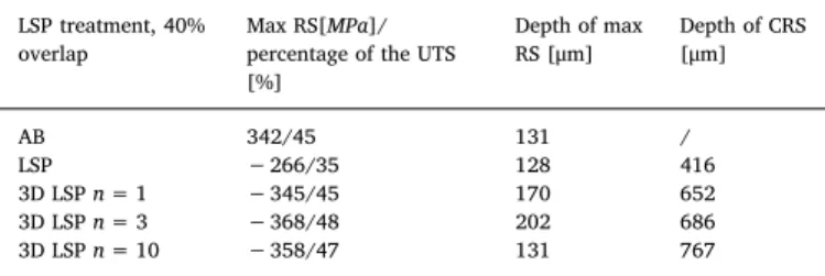
3.3.1. 3D LSP, 40% overlap
Residual stress measurements for the AB, LSP treated and 3D LSP treated samples are shown inTable 3, and a graphical representation of the stress profiles is given inFig. 7. 3D LSP samples have a very similar max RS of−345 MPa (45% of UTS), −368 MPa (48%) and −358 MPa (47%) for n = 1, 3 and 10 SLM layers, respectively. This represents a significant increase of Max RS when compared to a conventional surface LSP treatment, leading to an improvement of 30%, 38% and 35%, respectively. This result was not obvious, due to the possible relaxation of stresses from thermal effects induced by the SLM rebuild-ing step, and the associated generation of tensile stresses. However, an accumulation of CRS was observed for all 3D LSP processing parameters (Figs. 7 and 8). This indicates that the stress relaxation caused by the subsequent laser melting of even multiple n SLM layers during the rebuilding step is not the dominant effect, and that the 3D LSP does lead to a clear increase in magnitude and depth of CRS compared to a conventional LSP treatment.
The depth of CRS varied from 416μm for the conventional LSP treatment, to 652μm, 668 μm and 767 μm for the 3D LSP cases (n = 1, 3 and 10), showing an increase of 57%, 65% and 84%. The general trend which can be extracted from these results is that an increase in n leads to an increased depth of CRS. As mentioned above, this result was not straightforward. Since the melting and solidification of an SLM layer is very fast, it introduces a limited amount of heat and does not lead to full stress relaxation. CRS can therefore accumulate. The details of these mechanisms will however require further investigation. It is expected that there will be a critical value nc beyond which the
cumulative effects on the magnitude and depth of CRS will start decreasing. The value of ncitself should be a function of SLM processing
parameters and scanning strategy. In the present case, as mentioned in
Section 2.1, the least favorable SLM parameters and scanning strategy Table 3
Results of RS measurements: maximum RS/normalized by UTS; depth of maximum RS; depth of CRS. Measurements are made in the as-built state (AB); LSP treatments of 1 mm, 40% overlap; 3D LSP 1 mm 40% with 1,3 and 10 rebuilt layers.
LSP treatment, 40% overlap
Max RS[MPa]/ percentage of the UTS [%] Depth of max RS [μm] Depth of CRS [μm] AB 342/45 131 / LSP −266/35 128 416 3D LSP n = 1 −345/45 170 652 3D LSP n = 3 −368/48 202 686 3D LSP n = 10 −358/47 131 767
were selected on purpose, to show the potential of the 3D LSP process, hence leaving space for further improvement.
3.3.2. 3D LSP, 80% overlap
Residual stress measurements after treatments with 80% overlap are shown in Table 4 and Fig. 8. 3D LSP samples had a max RS of −667 MPa (88% of UTS), −707 MPa (93%) and −756 MPa (99%) for n = 1, 3 and 10 SLM layers, respectively. These values are very similar to those produced by a conventional LSP treatment (−730 MPa or 94% of UTS), which already indicate a high strain hardening level due to a high density of shots when working with a 80% overlap.
The depth of CRS was increased from 804μm for the conventional LSP treatment to over 1 mm, beyond the maximum depth investigated with the current hole drilling experimental setup. At the 1 mm depth, remaining compressive stresses were 38 MPa, 52 MPa and 254 MPa for n = 1, 3 and 10, respectively. This is not only a significant increase compared to the conventional LSP treatment, but also compared to the LSP treatment with 5 mm spot size (seeTable 2andFig. 5). These results illustrate the relevance of choosing a small spot size in 3D LSP, as the LSP affected zone depth can be even higher than the one produced by larger spot sizes in conventional LSP treatments. Similarly to the 40% overlap case, an increase in n leads to a significant increase in depth of CRS.
4. Conclusions and future work
In this paper, we have demonstrated the capability of an LSP treatment to change the residual stress state of SLM parts. Tests were performed on an austenitic 316L stainless steel, for which a highly tensile state of the AB sample was converted into a CRS state. It was also shown that if SLM building phase alternates with LSP treatments, both the magnitude and depth of maximum CRS can be significantly increased. Various LSP processing parameters were tested, and it can be concluded that:
•
A conventional LSP treatment easily converts TRS into a CRS state•
A smaller spot size leads to a larger maximum CRS•
A larger spot size leads to increased depth of CRS.•
Higher overlap rates (80%) lead to higher CRS and deeper CRS profiles due to a larger density of impacts on the treated surface. Although this LSP processing condition leads to better results, it increases the LSP treatment time.•
3D LSP increases both the magnitude and depth of CRS. This was observed for all processing conditions•
3D LSP with a reduced spot size and pulse energy can produce deeper CRS than those induced by a conventional LSP treatment with a larger spot size and pulse energy. This was observed for both 40% and 80% overlap, and proves the interest of using lower energy pulsed lasers with higher repetition rates and reduced processing time. Such lasers are also better suited for implementation into a single SLM-LSP hybrid machine, being smaller in size, cheaper, and more easily adaptable in terms of beam delivery and positioning.•
Increasing the number of SLM layers between LSP treatments leads to an increase of CRS depth.Further work will focus on (i) more accurate investigation of the effects of the number of SLM layers between two subsequent LSP treatments, (ii) the development of a prototype machine for the building of larger samples with optimized spatial distribution of tensile and compressive stresses, (iii) the assessment of fatigue life of 3D LSP treated samples, and the comparison with samples subjected to a conventional surface LSP treatment.
Another research direction will relate to the manufacturing of Fig. 8. Residual stress curves measured for samples in the AB, LSP 1 mm 80% and 3D LSP 1 mm 80% with 1, 3 and 10 rebuilt layers.
Table 4
Results of RS measurements: maximum RS/normalized by UTS; depth of maximum RS; depth of CRS. Measurements are made in the as-built state (AB); LSP treatments of 1 mm, 80% overlap; 3D LSP 1 mm 80% with 1, 3 and 10 rebuilt layers.
LSP treatment, 80% overlap
Max RS[MPa]/ percentage of the UTS [%] Depth of max RS [μm] Depth of CRS [μm] AB 342/45 131 / LSP −730/96 94 804 3D LSP n = 1 −667/88 165 > 1 mm (−38 MPa at 1 mm) 3D LSP n = 3 −707/93 126 > 1 mm (−52 MPa at 1 mm) 3D LSP n = 10 −756/99 243 > 1 mm (−254 MPa at 1 mm)
materials which are known to fail in SLM conditions due to the accumulation of high TRS, and for which the combination with 3D LSP is anticipated to be beneficial.
References
[1] Wohlers report.http://www.wohlersassociates.com/2012report.htm, (2012) ([Online]. Available, Accessed: 11-Sep-2015).
[2] R.S. Gideon, N. Levy, Rapid manufacturing and rapid tooling with layer manufac-turing (LM) technologies, state of the art and future perspectives. CIRP Ann—Manuf Technol 52 2:589–609, CIRP Ann. Manuf. Technol. 52 (2) (2003) 589–609. [3] W.E. Frazier, Metal additive manufacturing: a review, J. Mater. Eng. Perform. 23
(6) (Jun. 2014) 1917–1928.
[4] L. Thijs, J. Van Humbeeck, K. Kempen, E. Yasa, J.P. Kruth, M. Rombouts, Investigation on the inclusions in maraging steel produced by selective laser melting, Innovative Developments in Virtual and Physical Prototyping, 0 Vols, CRC Press, 2011, pp. 297–304.
[5] H. Stoffregen, K. Butterweck, E. Abele, “Fatigue Analysis in Selective Laser Melting: Review and Investigation of Thin-walled Actuator Housings,” Presented at the 25th Solid Freeform Fabrication Symposium 2014, Austin, Texas, (2014), pp. 635–650. [6] T.H. Becker, M. Beck, C. Scheffer, Microstructure and mechanical properties of
direct metal laser sintered TI-6AL-4V, S. Afr. J. Ind. Eng. 26 (1) (Mar. 2015) 1–10. [7] X. Tan, et al., Graded microstructure and mechanical properties of additive
manufactured Ti–6Al–4V via electron beam melting, Acta Mater. 97 (Sep. 2015) 1–16.
[8] L.T.B. Vrancken, Microstructure and mechanical properties of a novelβ titanium metallic composite by selective laser melting, Acta Mater. 68 (15) (2014) 150–158. [9] E. Sallica-Leva, A.L. Jardini, J.B. Fogagnolo, Microstructure and mechanical
behavior of porous Ti–6Al–4V parts obtained by selective laser melting, J. Mech. Behav. Biomed. Mater. 26 (Oct. 2013) 98–108.
[10] H.K. Rafi, D. Pal, N. Patil, T.L. Starr, B.E. Stucker, Microstructure and mechanical behavior of 17-4 precipitation hardenable steel processed by selective laser melting, J. Mater. Eng. Perform. 23 (12) (Sep. 2014) 4421–4428.
[11] J.-P. Kruth, M. Badrossamay, E. Yasa, J. Deckers, L. Thijs, J. Van Humbeeck,“Part and material properties in selective laser melting of metals,” Presented at the Proceedings of the 16th International Symposium on Electromachining, (2010). [12] E. Yasa, K. Kempen, J.-P. Kruth, L. Thijs, J. Van Humbeeck,“Microstructure and
mechanical properties of maraging steel 300 after Selective Laser Melting,” Presented at the Solid Freeform Fabrication Symposium Proceedings, (2010). [13] K. Kempen, L. Thijs, J. Van Humbeeck, J.-P. Kruth, Mechanical properties of
AlSi10Mg produced by selective laser melting, Phys. Procedia 39 (2012) 439–446. [14] C. Casavola, S.L. Campanelli, C. Pappalettere, Experimental analysis of residual
stresses in the selective laser melting process, Proccedings of the XIth International Congress and Exposition, Orlando, Florida, USA, 2008.
[15] J.-P. Kruth, J. Deckers, E. Yasa, R. Wauthle, Assessing and comparing influencing factors of residual stresses in selective laser melting using a novel analysis method, Proc. Inst. Mech. Eng. B J. Eng. Manuf. 226 (6) (Jun. 2012) 980–991.
[16] E. Brandl, U. Heckenberger, V. Holzinger, et al., Additive manufactured AlSi10Mg samples using selective laser melting (SLM), Mater. Des. 34 (2012) 159–169. [17] A.B. Spierings, T.L. Starr, K. Wegener, Fatigue performance of additive
manufac-tured metallic parts, Rapid Prototyp. J. 19 (2) (Mar. 2013) 88–94.
[18] K.R.H. Gong, Effect of defects on fatigue tests of as-built TI-6AL-4V parts fabricated by selective laser melting, 23rd Annu. Int. Solid Free. Fabr. Symp. - Addit. Manuf. Conf. SFF, 2012 2012, pp. 499–506.
[19] A.S. Wu, D.W. Brown, M. Kumar, G.F. Gallegos, W.E. King, An experimental investigation into additive manufacturing-induced residual stresses in 316L stain-less steel, Metall. Mater. Trans. A 45 (13) (Dec. 2014) 6260–6270.
[20] K. Kunze, T. Etter, J. Grässlin, V. Shklover, Texture, anisotropy in microstructure and mechanical properties of IN738LC alloy processed by selective laser melting (SLM), Mater. Sci. Eng. A 620 (Jan. 2015) 213–222.
[21] K. Kempen, B. Vrancken, S. Buls, L. Thijs, J. Van Humbeeck, J.-P. Kruth, Selective laser melting of crack-free high density M2 high speed steel parts by baseplate preheating, J. Manuf. Sci. Eng. 136 (6) (Oct. 2014) 061026.
[22] D. Buchbinder, W. Meiners, N. Pirch, K. Wissenbach, J. Schrage, Investigation on reducing distortion by preheating during manufacture of aluminum components using selective laser melting, J. Laser Appl. 26 (1) (2014) 012004.
[23] A.V. Gusarov, M. Pavlov, I. Smurov, Residual stresses at laser surface remelting and additive manufacturing, Phys. Procedia 12 (Part A) (2011) 248–254.
[24] M. Shiomi, K. Osakada, K. Nakamura, T. Yamashita, F. Abe, Residual stress within metallic model made by selective laser melting process, CIRP Ann. Manuf. Technol. 53 (1) (2004) 195–198.
[25] Peter Mercelis, Jean-Pierre Kruth, Residual stresses in selective laser sintering and selective laser melting, Rapid Prototyp. J. 12 (5) (Oct. 2006) 254–265. [26] P. Peyre, R. Fabbro, P. Merrien, H.P. Lieurade, Laser shock processing of aluminium
alloys. Application to high cycle fatigue behaviour, Mater. Sci. Eng. A 210 (1–2)
(Jun. 1996) 102–113.
[27] T.W. Charles, S. Montross, Laser shock processing and its effects on microstructure and properties of metal alloys: a review, Int. J. Fatigue 24 (10) (2002) 1021–1036. [28] R.K. Nalla, I. Altenberger, U. Noster, G.Y. Liu, B. Scholtes, R.O. Ritchie, On the
influence of mechanical surface treatments—deep rolling and laser shock peenin-g—on the fatigue behavior of Ti–6Al–4V at ambient and elevated temperatures, Mater. Sci. Eng. A 355 (1–2) (Aug. 2003) 216–230.
[29] I. Nikitin, B. Scholtes, H.J. Maier, I. Altenberger, High temperature fatigue behavior and residual stress stability of laser-shock peened and deep rolled austenitic steel AISI 304, Scr. Mater. 50 (10) (May 2004) 1345–1350.
[30] U. Trdan, M. Skarba, J. Grum, Laser shock peening effect on the dislocation transitions and grain refinement of Al–Mg–Si alloy, Mater. Charact. 97 (Nov. 2014) 57–68.
[31] N. Kalentics, E. Boillat, P. Peyre, S.Ćirić-Kostić, N. Bogojević, R.E. Logé, Tailoring residual stress profile of Selective Laser Melted parts by Laser Shock Peening, Addit. Manuf. (May 2017).
[32] N. Kalentics, R. Logé, E. Boillat,“Method and Device for Implementing Laser Shock Peening or Warm Laser Shock Peening During Selective Laser Melting,” United States Patent Application 20170087670 Kind Code: A1, (Mar 30 2017). [33] D. Lin, C. Ye, Y. Liao, S. Suslov, R. Liu, G.J. Cheng, Mechanism of fatigue
performance enhancement in a laser sintered superhard nanoparticles reinforced nanocomposite followed by laser shock peening, J. Appl. Phys. 113 (13) (2013) 133509.
[34] J.J. Ruschau, R. John, S.R. Thompson, T. Nicholas, Fatigue crack nucleation and growth rate behavior of laser shock peened titanium, Int. J. Fatigue 21 (Supplement 1) (Sep. 1999) S199–S209.
[35] A. King, A. Steuwer, C. Woodward, P.J. Withers, Effects of fatigue and fretting on residual stresses introduced by laser shock peening, Mater. Sci. Eng. A 435–436 (Nov. 2006) 12–18.
[36] Y.K. Gao, Improvement of fatigue property in 7050–T7451 aluminum alloy by laser peening and shot peening, Mater. Sci. Eng. A 528 (10–11) (Apr. 2011) 3823–3828. [37] O. Hatamleh, A comprehensive investigation on the effects of laser and shot peening
on fatigue crack growth in friction stir welded AA 2195 joints, Int. J. Fatigue 31 (5) (May 2009) 974–988.
[38] C.A. Rodopoulos, J.S. Romero, S.A. Curtis, E.R. de los Rios, P. Peyre, Effect of controlled shot peening and laser shock peening on the fatigue performance of 2024-T351 aluminum alloy, J. Mater. Eng. Perform. 12 (4) (2003) 414–419. [39] A.K. Gujba, M. Medraj, Laser peening process and its impact on materials properties
in comparison with shot peening and ultrasonic impact peening, Materials 7 (12) (2014) 7925–7974.
[40] D. Courapied, et al., Laser adhesion test for thermal sprayed coatings on textured surface by laser, J. Laser Appl. 28 (2) (May 2016) 022509.
[41] T. Schmidt-Uhlig, P. Karlitschek, M. Yoda, Y. Sano, G. Marowsky, Laser shock processing with 20 MW laser pulses delivered by opticalfibers, Eur. Phys. J. Appl. Phys. 9 (3) (Mar. 2000) 235–238.
[42] D. Courapied, L. Berthe, P. Peyre, F. Coste, J.-P. Zou, A.-M. Sautivet, Laser-delayed double shock-wave generation in water-confinement regime, J. Laser Appl. 27 (S2) (Feb. 2015) S29101.
[43] C. Correa, et al., Random-type scanning patterns in laser shock peening without absorbing coating in 2024-T351 Al alloy: a solution to reduce residual stress anisotropy, Opt. Laser Technol. 73 (Oct. 2015) 179–187.
[44] J.P. Nobre, M. Kornmeier, A.M. Dias, B. Scholtes, Use of the hole-drilling method for measuring residual stresses in highly stressed shot-peened surfaces, Exp. Mech. 40 (3) (Sep. 2000) 289–297.
[45] C. Rubio-González, et al., Effect of laser shock processing on fatigue crack growth
and fracture toughness of 6061-T6 aluminum alloy, Mater. Sci. Eng. A 386 (1–2) (Nov. 2004) 291–295.
[46] U. Trdan, J.A. Porro, J.L. Ocaña, J. Grum, Laser shock peening without absorbent coating (LSPwC) effect on 3D surface topography and mechanical properties of 6082-T651 Al alloy, Surf. Coat. Technol. 208 (Sep. 2012) 109–116.
[47] N.S. Rossini, M. Dassisti, K.Y. Benyounis, A.G. Olabi, Methods of measuring residual stresses in components, Mater. Des. 35 (Mar. 2012) 572–588.
[48] G.S. Schajer, Relaxation methods for measuring residual stresses: techniques and opportunities, Exp. Mech. 50 (8) (Jul. 2010) 1117–1127.
[49] V.M. Measurements, Measurement of residual stresses by the hole drilling strain gage method, Tech Note TN-503-6, 2007.
[50] F.Z. Dai, J.Z. Lu, Y.K. Zhang, D.P. Wen, X.D. Ren, J.Z. Zhou, Effect of laser spot size on the residual stressfield of pure Al treated by laser shock processing: simulations, Appl. Surf. Sci. 316 (Oct. 2014) 477–483.
[51] P. Peyre, R. Fabbro, L. Berthe, X. Scherpereel, A. Le Cornec, Laser Shock Processing With Small Impacts, 2789 (1996), pp. 125–132.
[52] P. Peyre, et al., Surface modifications induced in 316L steel by laser peening and shot-peening. Influence on pitting corrosion resistance, Mater. Sci. Eng. A 280 (2) (Mar. 2000) 294–302.
[53] P. Peyre, L. Berthe, X. Scherpereel, R. Fabbro, Laser-shock processing of aluminium-coated 55C1 steel in water-confinement regime, characterization and application to high-cycle fatigue behaviour, J. Mater. Sci. 33 (6) (Mar. 1998) 1421–1429.