Pathologies of concrete in Saint-Vincent Neo-Byzantine
Church and Pauchot reinforced artificial stone
L. Courard1, A. Gillard1, A. Darimont1, J.M. Bleus2 and P. Paquet3
1
University of Liège, ArGEnCo Department, GeMMe Building Materials, Chemin des Chevreuils, 1 – 4000 LIEGE, Belgium
2
University of Liège, Faculty of Architecture, Boulevard de la Constitution 41 - 4020 LIEGE, Belgium
3
University of Liège, ArGEnCo Department, Arkhé Group, Chemin des Chevreuils, 1 – 4000 LIEGE, Belgium
Abstract
Reinforced concrete is a key element of the architectural evolution and has been specifically involved in the development of Catholic Church architecture, particularly during the second part of the XXth century.
This article focuses on the Saint-Vincent Church, Liege district, Belgium. With concrete as major building material, this was built in only 20 months, from 1928 to 1930. This monumental building, from Neo Byzantine style, however presents some degradations. A visual inspection, as well as non destructive and laboratory tests, are presented and analysed. They help to make a clear diagnosis and to assess hypothesis on the real state of this high-quality architectural building. Moreover, specific investigations have been realized on a special mortar used for wall construction: Pauchot reinforced artificial stone.
Keywords: concrete, church, architecture, pathology, diagnosis, Pauchot reinforced
artificial stone, spalling, carbonation, corrosion
1 Introduction
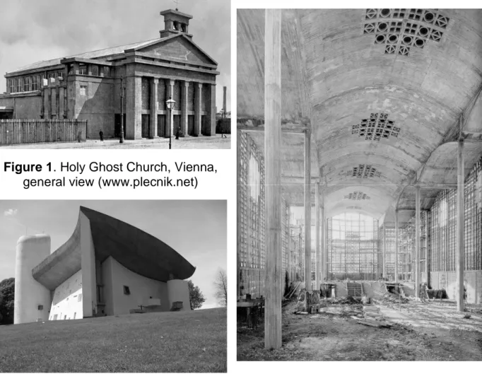
Concrete remains a high-performance and durable material but the explosion of the quantity of concrete used for constructions and buildings after the Second World War has resulted in an acceleration of maintenance and repair operations on such structures [1]. Concrete structures have been widely designed all over the world and, with regards to the number of bridges, dams, roads and buildings, only some of them presented so large degradations that they collapsed or they were destroyed [2]. Reinforced concrete is indeed a key element of the architectural evolution [3, 4] and has been specifically involved in the development of religious architecture (Fig. 1). The first religious monument entirely made of concrete was likely built overseas in 1908, i.e. the united church by Frank Lloyd Wright, architect, in Oak Park, Illinois, U.S.A. [5]. Wright immediately took advantage from playing with texture and colour of the materials, using specific aggregates [6].
Architects like Plečnik [7] (Figure 1), Perret [8], Le Corbusier (Figure 2) or Nervi [9] also used reinforced concrete to open the space and let the light enter the religious edifice: “concrete” glass window became a sort of trade mark of such monument. The space, more open and enlightened, becomes more welcoming. Economy in time and materials is another essential factor that seemed to be attractive for architects: cement, sand, aggregates are usually not expansive but also available in the neighborhood of any work site. Moreover, concrete is easy to produce and to cast: this contributes to decrease production costs.
Figure 1. Holy Ghost Church, Vienna,
general view (www.plecnik.net)
Figure 2. Notre-Dame-du-Haut Chapel,
Ronchamp (France) (www.photos.igougo.com)
Figure 3. Notre-Dame-de-la-Consolation
Church, Le Raincy (France), interior view during works (Abram J. et al., 2000)
Another building clearly shows the contribution of concrete in religious architecture: Notre-Dame-de-la-Consolation in Raincy, France, which is the first religious building designed by the Perret brothers [8] and listed in patrimonium in 1966 (Figure 3). The rectangular simple plan is partitioned by four rows of pillars, which define a nave and two aisles [10]. The construction mode and the use of concrete allowed again a very quick erection of the church (the work began in June 1922 and the church was consecrated a year later). The budgets have failed to decorate the concrete, left naked, but "more than a manifesto of raw concrete, the Church of Raincy must
therefore be seen as an opportunity, born of constraint, to give to concrete its proper expression "[8].
Finally, a last but not least concrete-based religious monument is the Gaudi’s Sagrada Familia Church in Barcelona [11]. This is however a counter example of the advantages pointed out by architects: it is still under construction for more than 100 years! But once again, it is one of the most important milestones in the development of Catalan Modernism at the beginning of the 20th century [11].
Our investigations take place into a larger research project on the history of concrete-based churches through the world and in Belgium: the objectives are a better view of the sanitary situation of these concrete religious monuments as well as the rehabilitation processes needed to restore and/or repair materials and structures. This article presents an architectural analysis of the Saint-Vincent Church, in Liège district, Belgium [10], with a focus on the use of concrete, specifically Pauchot reinforced artificial stone.
2 Saint-Vincent Church 2.1 History
Among the nine churches built with concrete in Liège district [12], Belgium, the Saint-Vincent Church (Figure 4) is the oldest but also the first religious building designed by Robert Toussaint, then a young architect. It represents a very important witness, from historical perspective and technical points of view [13]. The construction of this church, completed in less than twenty months (Figure 5), is actually involved into the evolution and the urban planning extension of the city of Liège and the Universal Exhibition in Liège in 1905 [12]. Erected near Mativa Bridge, designed by Hennebique [13, 14], it was completed just before the celebration of the centenary of the Belgian independence.
Figure 4. Global view of Saint-Vincent
church (May 2010)
Figure 5. Saint-Vincent Church before
copper roofing placement (1930) [16]
Moreover, new material has been used in several parts of the edifice, mainly in the walls: Pauchot reinforced artificial stone [12]. This material is named after the company that took in charge the structural work of the church. The family company of Pauchot brothers, originally based in Paris since 1919, was also active in Belgium (Brussels). It however ceased operations in early 1930, due to the economic crisis. There are currently very few traces of his accomplishments.
2.2 Architectural description
Massive church plan, of neo byzantine style, is centered on an oriented north-south axis, parallel to the Ourthe river, which borders the edifice (Figure 6). Its length, reaching 57 m, is hardly larger than its width, 49 m, respectively.
Figure 6. Scheme and plan of Saint-Vincent Church [15] Figure 7. Parvis and bell
tower in front of the Saint-Vincent Church A large dome (15m high - 22.40m diameter – 50.50m top) covers the building. It is protected with copper (now oxidized) as the peripheral semi-domes. The main entrance is south oriented. It is underlined by an arch and preceded by a parvis (Figure 7). It provides access to the nave. The nave, covered by a half-cylinder and topped with a steeple, extends the central rotunda, in the form of irregular octagon (Figure 8); it is surrounded by a walkway, which separates itself the three main apses and four secondary apses (Figure 6).
Figure 8. Saint-Vincent church, choir and
apses, with part of rotunda (from
Figure 9. Saint-Vincent church: sectional view at the apses level with
Samples 3 and 4
www.kikirpa.be) double concrete deck (Dec. 10th, 1953) [17].
There is a gallery which runs almost the entire church (along the facades). The slope of the land allows space under the choir, giving direct access to the basement.
Finally, the architect has ensured that the whole church is accessible: a stairway serving the building's basement to above the nave and a staircase used to reach the outer gallery, located under the central dome; there is a ramp, along the central interior dome which ends with a spiral staircase leading to the lantern on the top of the church (Figure 3).
Archives shows that concrete was directly cast on the site and that traditional wooden plank sheeting (Figures 10 and 11) were used for casting; the absence of spacers resulted, in some cases, the positioning of the frame very close to the surface (Figure 13).
Figure 10. Formworks and building of
choir and apse (Jan. 15th, 1930) [16]
Figure 11. Formworks and scaffolding
for dome building (Nov. 7th, 1929) [16]
2.3 Structural description
The main nave of Saint-Vincent church offers a double concrete structure, in the shape of a frame (Figure 12).
Figure 12. Saint-Vincent church: sectional view of the nave reinforced concrete
frame and the structure [15].
The central dome, such as the half-domes and the roof covering the nave, are actually made of double bottom (Figure 12). Reinforced concrete shells are connected with reinforced concrete beams like frames: it looks like a steel frame structure (Figure 13). The roofs are made of a reinforced concrete shell with a thickness of 70 mm. The load of central domes is supported by eight hollow pillars, which delimitate the rotunda (Figure 12). The inner vault of the nave is based on eight secondary pillars, while the outer one rests on pillars inserted in the facade. Loads are then transferred through beam-pillar systems.
Figure 13. Reinforced concrete frame structures (between dome shells)
Under the ground floor, a grid of beams transmits all loads to the pillars, resting on Franqui type piles (Figure 14). About 230 piles were driven under the church, at a
depth ranging between 10 and 12 m: the church is indeed above a backfilled ancient river deviation.
In general, the walls are made of a double structure. Samples taken through the wall at the ground level indicated the following composition (from inside to outside):
• a wall (apparently made of blocks) of concrete, 16 cm thick (Figure 14); • a vacuum of 13.5 cm thick;
• Pauchot reinforced artificial stone, about 12 cm thick (Figures 15 and 16).
Figure 14. Sample of concrete (internal
wall, Saint-Vincent church)
Figure 15. Internal face of Pauchot
reinforced artificial stone sample from Fig. 14 (Saint-Vincent church)
Figure 16. Sample of Pauchot
reinforced artificial stone (external wall, Saint-Vincent church)
This structure has been confirmed by GPR technique [18]: the principle of radar is to issue a high frequency electromagnetic wave in the wall. The wave will propagate into the medium and be reflected at the interface between different environments (eg at the transition between the concrete and vacuum or between concrete and reinforcement).
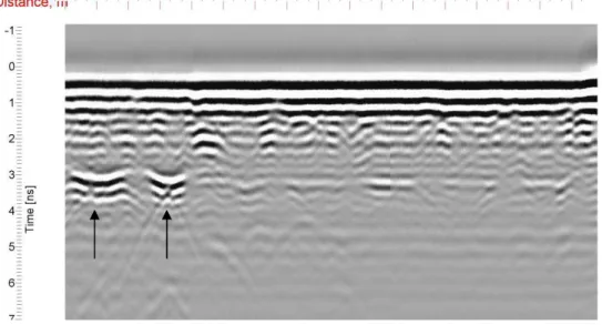
Figure 17. Saint-Vincent Church: radar signal obtained in the stair case, under
spalling visible in Figure 18
In Figure 17 a horizontal reflector is observed at a depth of 12 cm (for a speed of 13 cm/ns). It is probably the void behind the wall, under the apparent lattice visible in Figure 18 (situation as sample 1(Figure 6)). At the level of these reflectors are semi-hyperbolic waves (↑), which is consistent with the presence of joints and probably indicate the presence of blocks.
Figure 18. Spalling of Pauchot reinforced artificial stone (staircases, Saint-Vincent
church).
On the recorded signal at the base of the staircase (Figure 19), there is a horizontal reflector and regularly spaced frames in the right part. On the left, a reflector is marked down: it could correspond to the transition from Pauchot reinforced artificial stone and a concrete wall, probably composed of blocks, which is attested once again by the presence of half-hyperbolas evenly spaced at the horizontal reflector (←).
Figure 19. Saint-Vincent Church: radar signal obtained at the base of the staircase
Other samples showed different compositions, perhaps due to a too rapid execution of the work. Pauchot artificial stone, reinforced with wire mesh placed at 45°, is supposed to imitate the stone from France. False joints have also been painted on the facades.
2.4 Pathologies of structures and materials
The proper planning of investigations before carrying out repair works is important if optimum use is to be made of the test data. Engineers require guidance on both the techniques available for the condition assessment of structures and the methods for data interpretation. Two major stages are usually recommended for such an operation: the first stage is based on a rapid-scan visual assessment, often including limited sampling in areas obviously damaged, from which areas can be selected for more detailed investigations. The second stage contains a detailed diagnostic survey that relies on destructive and non destructive testing techniques [19].
Non destructive techniques are more and more utilized not only for the evaluation of the concrete strength but also for the detection of cracks and delaminations [20]. In general, the concrete material may offer three types of damage: cracks, spalling or disintegration [2, 21, 22].
Cracking (Figs. 20 and 21) mainly originates from structural problems as restrained
deformations (with variations in temperature and humidity), deformation of the support, unbalanced loading or horizontal stresses in alternating directions [21]. The drying shrinkage or alkali-aggregate reaction may also lead to cracks but, in either case, cracks open moderate and are organized in a network (referred to as crazing).
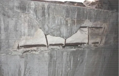
Spalling (Figs. 23 to 26) means the debonding of pieces of concrete from their
support. The dissociation follows tensile stresses into concrete, often caused by corrosion of steel reinforcement [22, 23]. The problem may be further amplified by an action of frost on an area saturated with water.
Corrosion of steel (Figs. 23 and 26) can be due to an attack by chlorides (from
de-icing salts or accelerators) or the carbonation of concrete surrounding the reinforcement [24]. Too low cover of reinforcement promotes the corrosion reaction [25]. Finally, the disintegration of the concrete may also result from an attack by bacteria or acid products.
In Saint-Vincent church, a visual inspection was performed in order to identify damages and pathologies according to recommendations of Duvivier and Montfort [26].
The main structural damages that have been reported are [27]:
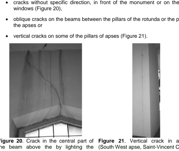
• cracks without specific direction, in front of the monument or on the top of windows (Figure 20),
• oblique cracks on the beams between the pillars of the rotunda or the pillars of the apses or
• vertical cracks on some of the pillars of apses (Figure 21).
Figure 20. Crack in the central part of
the beam above the by lighting the gallery (East front, Saint-Vincent Church)
Figure 21. Vertical crack in a pillar
(South West apse, Saint-Vincent Church)
These last one may be related to the presence (confirmed by radar [18, 19]) of metal pipes discharging rainwater from the central dome. The position of the vertical cracks visible on the front of the pillars coincides with the hyperboles (↑) identified by the radar (Figure 22). This would support the hypothesis attributing the presence of cracks to a deformation of the pipes, maybe caused by insufficient flow diameter.
Figure 22. Saint-Vincent Church: radar signal obtained from pillar
between West and South-West apses.
The origin of other vertical cracks however could not be yet identified on the basis of available information. In all cases, the installation of plaster witnesses would confirm a potential movement of the cracks. It will be followed, if necessary, by the installation of sensors, recording the movement of the lips of the cracks, providing the evolution of this movement over time.
It may be noted that, in addition to the bombings of World War II, the Saint-Vincent Church suffered the earthquake of 1983. Later also held the derivation of a nearby stream, to the Ourthe river. After this diversion, settlements appeared in the gardens of houses adjacent to the church and it is not unlikely that the ground under the church has also borne the brunt of this change in water courses.
These three events have possibly exacerbated the movement of the structure.
In addition, spalling was found as a main degradation all along the facade of the church (Figure 23), particularly around bays (Figure 24). At this level, the cover of steel reinforcement is sometimes very thin (Figures 25 and 26). Other traces of spalling were visible in the stairwell and under the central dome (Figure 13). Between the arches spanning the nave and the lantern, corroded steel bars are also flushing with concrete skin.
Carbonation depth and thin steel reinforcement cover seem to be the main causes of spalling.
Figure 23. Spallings around the North
West bay of the choir, Saint-Vincent Church
Figure 2’. Spallings around a North bay,
Saint-Vincent Church
Figure 25. Spallings under window
sill, Saint-Vincent Church
Figure 26. Typical spalling inside Pauchot
reinforced artificial stone, North West apse, Saint-Vincent Church
Finally, inside the church, along the gallery, traces of moisture have been noticed, at floor and ceiling levels. In some places, stains of rusty dirty walls or pillars.
2.5 Analysis of Pauchot reinforced artificial stone
This material has been used for the outside part of the church walls; it may be considered as fulfilling material which is not submitted to external loading except dead weight.
Mechanical and physical performances (Table 1) have been evaluated on the base of cores from different locations all around the church. These locations were selected with regard the apparent degradation level and for aesthetic purposes: it was avoided taking cores in too visible parts of the church. Proper location is reported on Fig. 6; samples are cored at human height.
Table 1: Physical and mechanical properties of Pauchot reinforced artificial stone
strength [S1] [N/mm²] strength [S2] [N/mm²] absorption [S3] [% in mass] mass [S4] [kg/m³] 1 18.1 1.48 10.86 1875 2 20.9 1.58 10.55 1887 3 19.7 0.78 10.69 2012 4 11.1 1.42 10.48 1941
Compressive strength is characteristic of a good quality mortar or a basic concrete. Tensile strength is maximum 0.8 times compressive strength; water absorption is quite high.
Capillary absorption tests have been performed in order to analyse water ingress and capacity of the mortar to resist to fluid penetration. The capillary suction test is described by Belgian standard NBN B 14-201 [S5]: the water level above the bottom surface of concrete specimen is 5 ± 1 mm and the mass variation is measured after 5, 15, 30 and 45 minutes as well as after 2, 6 and 24 hours, respectively [27]. Mass is measured on samples wiped off with a damp tissue.
The absorption coefficient, S, calculated according to NBN B 15-250 [S6], is given in Table 2.
Table 2 : Capillary absorption coefficients
Sample 1 2 3 4
S [kg/mm²/h1/2] 3,06. 10-6 3,06. 10-6 5,88. 10-6 2,45. 10-6 S [kg/m²/h1/2] 3,06 3,06 5,88 2,45
For repair mortars, the standard EN 1504-3 [S7] fixed at 0.5 kg / m² / h1/2 the upper limit for the absorption coefficient; the values given by the Pauchot reinforced artificial stone are much higher. They are related to the porosity of the material (see test water absorption in Table 1), which is itself linked to the low density samples. The Pauchot reinforced artificial stone is closer to a cellular concrete, as shown in Table 3, with regard to the values of capillary rise (Table 3).
Table 3: Capillary rise coefficients for cellular concrete and Pauchot reinforced
artificial stone
Cellular concrete Ytong1 Pauchot reinforced artificial stone C3/450 C4/550 Sample 1 Sample 2 Capillary rise [mm]
after 3 hours 42 43 32.34 31.24 after 24 hours 61 69 74.99 75.15
1 Capillary rises into Ytong cellular concrete blocks measured according to standard NBN 538
Chloride content was measured twice for each of the three samples [S6]. The values obtained, expressed as mass percentage of chloride ions, relative to the mass of cement, are shown in Table 4.
Table 4: Determination of chloride content
Sample 1 Sample 3 Sample 4
1 2 1 2 1 2
Chloride content [%] 0.038 0.031 0.029 0.031 0.031 0.033
According to EN 206-1 [S8], the maximum chloride accepted for concrete containing steel reinforcement or embedded metal varies between 0.20 and 0.40%. The values presented in Table 4 are far from the threshold and can already rule out the possibility of corrosion due to attack by chlorides, for the samples considered
Carbonation depth was measured by using phenolphtalein indicator: some samples are completely carbonated (110mm) while others are only partially carbonated. It means that the material, which has been cast on site, was probably variable into its composition as well as its working procedure.
These considerations are confirmed by microscopical investigations.
Large air bubbles and voids are observed on thin slices samples (Figure 27). Limestone sand seems have been used and CaCO3 crystals are numerous (Figure
29): this is probably due to high lime content for preparing mortar. Cement is however largely present in some samples, attesting the use of this hydraulic binder. The structure is lumpy. The grains of carbonates can be detached from the cement paste. Lime can be carbonated. There is no cohesion in cement paste and the interface between the grains of limestone is often broken (Figure 28).
(a) (b)
Figure 27. Optical microscope on Pauchot artificial stone - (a) sample 1 and (b)
sample 3.
Figure 28. Cementitous matrix from
Pauchot artificial stone (view ESEM – sample 3)
Figure 29. Calcite crystals from Pauchot
artificial stone (view ESEM – sample 1) The chemical and physical tests (Table 1) and microscopical observations (Figures 27 to 29) carried out on samples of Pauchot reinforced artificial stone revealed a heterogeneous material composition, more similar to a mortar or light concrete than a conventional reinforced concrete. It is porous and offers a compressive strength ranging from 11.1 to 20.9 MPa. The chemical analysis revealed a very low chloride concentration, eliminating the risk of corrosion attack of chlorides for these samples and favoring the hypothesis of corrosion by carbonation (the more likely that porosity of the artificial Pauchot stone is important and the urban environment in which the church is polluted).
3 Conclusions
The following conclusions may be reached from the present investigations concerning the behaviour of the concrete in Saint-Vincent Church:
• first of all, if the degradations observed in Saint-Vincent Church are numerous, they do not seem to jeopardize the safety of the faithful people;
• Pauchot reinforced artificial stone has been largely used as filling and facing material for walls. Physico-chemical analyses show a great variability and quite high porosity. This is not unusual for mortars but it can be a source of degradations when used in present conditions;
• high porosity has induced large area where carbonation depth is larger than recovery of steel reinforcement. This situation is the main cause of corrosion and spallings all over the church;
• structural defects are visible, mainly in the form of cracks due to differential movements of parts of the structures. These differential displacements may be due to soil settlements or thermal gradients;
• particular attention should be paid to the presence of water and humidity, as a source of discomfort, but also damage by corrosion.
Degradations pointed out in Saint-Vincent church could be solved by removing of the carbonated concrete, specifically Pauchot reinforced artificial stone, protecting steel rebars from corrosion and applying a less porous mortar as cover material.
The situation of Saint-Vincent Church illustrates the problem that appears in several concrete religious monuments, yet often overlooked. In the district of Liège, an inventory, followed by a visual inspection, was performed. Much work remains to be done in that direction and within a relatively short time so that the management of these architectural witnesses remains possible.
Aknowledgments
The authors wish to express their gratitude and sincere appreciation to the University of Liège, for financing this research (Research Project Surface characterization of
concrete historical structures: cohesion and aspect).
Special thanks are addressed to F. Michel, mst. geol. eng., technical manager of the Building Materials Laboratory for advices, Audrey Van der Wielen, civ. eng. and Thomas Hermans, geol. eng., doctorate students in the Department of Architecture, Geology, Environment and Construction of the University of Liège, who performed radar investigations, and Jérôme Colson, mst. Student from the École Nationale
Supérieure des Ingénieurs en Arts Chimiques et Technologiques, Toulouse, who was
in charge of specific physical and chemical tests on Pauchot reinforced artificial stone.
References
1. Czarnecki L., Vaysburd A.M., Mailvaganam N.P., Emmons P.H. and McDonald J.E. “Repair and rehabilitation of structures – some random thoughts”, Indian
Concrete Journal, 2000, 74, 13-20.
2. Courard L., Van der Wielen A. and Darimont A. “From defects to causes: pathology of concrete and investigation methods”. 17th Slovenski kolokvij o betonih, Ljubljana, Slovenia (19 mai 2009), 29-48.
3. Simonnet C., Le béton : histoire d’un matériau, Marseille, Ed. Parenthèses, 2005, 219p.
4. Espion B., Du "ciment" des romains aux débuts du béton armé, Demi-journée d'étude FABI "Connaissez-vous les bétons armés? Des origines à 1914", 26 octobre 2010, Namur.
5. Kind-Barkauskas F., Kauhsen B., Polonyi St., Brandt J., Construire en béton.
Conception des bâtiments en béton armé, Lausanne, 2006, 9-44.
6. Brooks Pfeiffer B., Frank Lloyd Wright, Köln, Taschen, 2008.
7. Krečic P., Plečnik. Une lecture des formes, Liège, Mardaga, 1992.
8. Abram J., Lambert G., Legault R., Ragot G., Texier S., Les Frères Perret.
L'oeuvre complète, Paris, Éditions Norma, 2000.
9. Torgerson M. A., An architecture of immanence. Architecture for worship and
ministry today, Grand Rapids, Eerdmans, 2007.
10. Gillard A., Courard L. and Paquet P. “Churches and concrete in Liège district: history, architecture and pathologies”. Restoration of buildings and monuments, 2011, 17(1), 3-14.
11. Grima R., Gomez Serrano J. and Aguado A., The Use of Concrete in Gaudi’s
Sagrada Familia, International Journal of Architectural Heritage, 2007, 1(4),
366-379.
12. Gillard A. Concrete in the parish churches of Liège district after World War II, Architecture in Liège during XXth century. Art&Fact., 2010, 29, 75-81 (in
French).
13. Bâtir (Revue mensuelle illustrée d'Architecture, d'Art et de Décoration), n°40, mars 1936.
14. Van de Voorde St., “Hennebique’s Journal Le béton armé. A close reading of the Genesis of Concrete Construction in Belgium”. Proceedings of the Third International Congress on Construction History (eds. K.-E. Kurrer, W. Lorenz, V. Wetzk.), Cottbus, 2009, 1453-1462.
15. La Technique des Travaux (Revue mensuelle des Procédés de Construction Modernes), avril 1934.
16. Cornet R., "La couverture en cuivre de l'église Saint-Vincent à Liège", Notes
techniques éditées par le centre belge d'information du cuivre, 1967 (pages
3-6).
17. Robert Toussaint Foundation, Groupe d’Ateliers de Recherche, Saint-Luc, Université de Liège, Faculté d’Architecture.
18. Van der WielenA., Courard L. and Nguyen F. Detection of Defects in Concrete
with Ground Penetrating Radar. ESPSC 2011, European Symposium on
Polymers in Sustainable Construction. Czarnecki Symposium. Warsaw (6-7 Sept. 2011), 221-225.
19. Robery, P.C. “Investigation methods utilizing combined NDT techniques”,
Construction Repair, 1995, 9(6), 11-16.
20. Czarnecki, L. “Mechanisms of Industrial Floors Deterioration – Causes, Results and Preventive Means”, Fifth International Colloquium Industrial Floors ‘03, Esslingen, Germany (Technische Akademie Esslingen, Ed. P. Seidler), 2003, pp.65-72.
21. Plumier A., Pathology and structural repair of constructions, Liège, Université de Liège, ArGEnCo Department, Faculty of Applied Sciences, 2009 (in French). 22. Emmons, P.H. Concrete Repair and Maintenance illustrated. RS Means,
Construction Publishers&Consultants, Kingston (MA), USA, 295p, 1993.
23. Masayasu, O. and Yosimura, S. “Analysis of crack propagation and crack initiation due to corrosion of reinforcement”, Construction and Building
Materials, 1997, 11(7-8), pp.437-442.
24. Vaysburd, A. M. and Emmons, P.H. ‘How to make today’s repairs durable for tomorrow – corrosion protection in concrete repair’. Construction and Building
Materials, 2000, 14 (4) 189-197.
25. Courard L. and Garbacz A. ‘Surfology: what does it mean for polymer concrete composites?’ Restoration of Buildings and Monuments, 2010, 16 (4/5), 291-302.
26. Duvivier P. and Monfort B. Methodology for the preparation of restoration works
in concrete monuments. Master Thesis. Faculté des Sciences Appliquées,
Université de Liège, Belgium: 203p (in French).
27. Gillard A., Courard L. and Darimont A. Saint-Vincent church: visual inspection
and test program, Internal report, University of Liège, 2010, 65p.
28. Courard L. And Degeimbre R. A capillary suction test for a better knowledge of
adhesion process in repair technology. Can. J. Civil Eng., 2003, 30(6),
Standards
S1. NBN EN 12390-3: 2002. Testing hardened concrete - Part 3: Compressive strength of test specimens. European Committee for Standardization, Brussels. S2. NBN B15-211: 1974. Concrete testing - Direct tensile strength. NBN, Brussels S3. NBN B15-215: 1987. Concrete testing - Absorption of water by immersion.
NBN, Brussels
S4. NBN EN 12390-7: 2001. Testing hardened concrete - Part 7: Density of hardened concrete. European Committee for Standardization, Brussels.
S5. NBN B 14-201: 1973. Test on mortars - Capillary suction test. NBN, Brussels. S6. NBN B 15-250: 1991. Chemical analysis of hardened mortar and concrete.
NBN, Bruxelles.
S7. EN 1504-3: 2005. Products and systems for the protection and repair of concrete structures – Definitions, requirements, quality control and evaluation of conformity – Part 3: Structural and non structural repair. European Committee for Standardization, Brussels.
S8. EN 206-1: 2004. Concrete — Part 1: Specification, performance, production and conformity. European Committee for Standardization, Brussels.
![Figure 5. Saint-Vincent Church before copper roofing placement (1930) [16]](https://thumb-eu.123doks.com/thumbv2/123doknet/6934606.195866/3.892.129.781.698.965/figure-saint-vincent-church-copper-roofing-placement.webp)
![Figure 6. Scheme and plan of Saint-Vincent Church [15] Figure 7. Parvis and bell tower in front of the](https://thumb-eu.123doks.com/thumbv2/123doknet/6934606.195866/4.892.565.763.230.529/figure-scheme-saint-vincent-church-figure-parvis-tower.webp)
![Figure 10. Formworks and building of choir and apse (Jan. 15th, 1930) [16]](https://thumb-eu.123doks.com/thumbv2/123doknet/6934606.195866/5.892.189.776.469.691/figure-formworks-building-choir-apse-jan-th.webp)
![Figure 12. Saint-Vincent church: sectional view of the nave reinforced concrete frame and the structure [15]](https://thumb-eu.123doks.com/thumbv2/123doknet/6934606.195866/6.892.240.648.108.348/figure-saint-vincent-church-sectional-reinforced-concrete-structure.webp)