UNIVERSITÉ DE MONTRÉAL
PRATICAL TERAHERTZ WAVEGUIDES FOR ADVANCED LIGHT MANAGEMENT
TIAN MA
DÉPARTEMENT DE GÉNIE PHYSIQUE ÉCOLE POLYTECHNIQUE DE MONTRÉAL
THÉSE PRÉSENTÉE EN VUE DE L’OBTENTION DU DIPLÔME DE PHILOSOPHIAE DOCTOR
(GÉNIE PHYSIQUE) JANVIER 2017
UNIVERSITÉ DE MONTRÉAL
ÉCOLE POLYTECHNIQUE DE MONTRÉAL
Cette thèse intitulée
PRACTICAL TERAHERTZ WAVEGUIDES FOR ADVANCED LIGHT MANAGEMENT
présentée par : MA Tian
en vue de l’obtention du diplôme de : Philosophiae Doctor a été dûment acceptée par le jury d’examen constitué de :
M. GODBOUT Nicolas, Ph. D, président
M. SKOROBOGATIY Maksim A., Ph. D, membre et directeur de recherche M. PETER Yves-Alain, D. Sc., membre
ACKNOWLEDGEMENTS
I would like to express my heartfelt gratitude to my supervisor and research director Prof. Maksim Skorobogatiy for his guidance and supports during my Ph.D. study, especially when I struggled in the predicaments. Maksim’s help allowed me to pursue successfully my scientific dream, become more mature, and enrich my curiosity.
I would like to thank all my friends and colleagues in Engineering Physics, Ecole Polytechnique de Montreal, Xin Lu, Hang Qu, Jingwen Li, Hichem Guerboukha, Katirvel Nallapan and others. I would like to thank them for the helpful discussions, constructive interactions and mutual support in the past four years. I also would like to thank the technicians in our group, Francis Boutet and Yves Leblanc, for their plenty of technical assistance.
Finally, I wish to thank my parents and Xin for their support during my doctoral study. They have always been understanding and patient, and I could always address to them for the encouragement and support when I needed it.
RÉSUMÉ
Avec la demande croissante de bandes passantes plus larges et de taux de transfert de données plus élevés, l’utilisation des térahertz (THz) pour les communications sans fil a connu un regain d’attention ces récentes années. En raison de ses faibles absorption et dispersion, le gaz est souvent vus comme les meilleurs médium pour transmettre la radiation THz. Aujourd’hui, de nombreux systèmes de communication THz se basant sur propagation à l’air libre ont été développés et étudiés, démontrant des taux de 100 Gbit/s pour des fréquences de porteuses sous 0.6 THz. Cependant, l’application de ces systèmes sont encore limités en raison des défis inhérents posés par une propagation en espace libre, tels qu’une forte dépendance aux conditions atmosphériques, une divergence rapide du faisceau THz (spécialement à basses fréquences) et le besoin de matériel optique distinct et d’alignement parfait. De plus, en raison de la forte directionalité des faisceaux THz, l’accès aux zones partiellement bloquées peutêtre compliqué et requiert des solutions additionnelles de manipulation des THz pour une communication fiable.
D’un autre côté, les guides d’ondes diélectriques offrent des solutions aux limitations d’une propagation à l’air libre. En particulier, la propagation dans les fibres THz scellés permet d’éviter les problèmes de communication liés à l’influence des conditions atmosphériques. De plus, ces fibres sont flexibles et permettent ainsi d’accéder à des zones physiquement obstruées. Finalement, la taille de ces fibres est comparable à la longueur d’onde, permettant des liens de communication compacts. Cependant, aucun système de communication basés sur les fibres n’existe actuellement. Les principales raisons sont les fortes absorptions et la dispersion dans ces guides d’onde.
Au cours de la dernière décennie, plusieurs fibres THz ont été proposées pour réduire les pertes. On peut donc considérer que ce problème est résolu. Cependant, la gestion de la dispersion est encore très peu étudiée dans la littérature. Dans cette thèse, j’explore différents types de guides d’onde diélectriques pour réduire à la fois les pertes et la dispersion dans le spectre des THz.
Premièrement, je présente un guide d’onde THz à cœur creux à bande interdite qui utilise des réflecteurs positionnés suivant une distribution hyperuniforme. La motivation première de ce guide d’onde est d’explorer la possibilité d’utiliser le design à cœur creux qui possède des larges bandes interdites potentiellement plus grandes que celle atteignables avec des structures simplement périodiques. En particulier, nous démontrons théoriquement qu’en utilisant la combinaison des matériaux résine/air à faible contraste d’indice 1.67/1, il est possible de désigner
un guide d’onde désordonné hyperuniforme avec une bande interdite de 90 GHz (21%) centrée à 0.41 THz. Ceci est comparable aux meilleurs records pour ses contreparties périodiques. Nos guides d’onde à cœur creux sont fabriqués en utilisant une impression 3D. Le diamètre du guide d’onde est ~20 mm alors que celui du cœur creux est de ~5 mm. En raison des limitations dans l’impression 3D, la résolution a été limitée à 100 µm, nous permettant d’imprimer des structures avec des ponts plus larges que 200 µm. Les résultats expérimentaux démontrent que les guides d’onde fabriqués ont des larges bandes interdites (jusqu’à 15%) et de faibles pertes de transmission (<0.10 cm-1) dans les bandes interdites.
Ensuite, nous démontrons un nouveau guide d’onde à gradient d’indice spécifiquement désigné pour la gestion de la dispersion dans les THz (THz GI-POF). La fibre est faite de polyéthylène et contient une distribution non uniforme de trous de différentes tailles. Tous ces trous sont sous longueur d’onde, résultant en un indice de réfraction effectif dans le médium. La forte porosité du guide d’onde permet en plus de limiter les pertes d’absorption du matériau. Ces dernières varient de 0.025 cm-1 à 0.3 THz jusqu’à 0.15 cm-1 à 1.5 THz. La dispersion modale des modes individuels a été réduite sous 1 ps/(THz cm) dans la région d’opération, en raison de l’utilisation de matériaux poreux et dûe à un large cœur. Quant à elle, la dispersion intermodale a été réduite sous 2 ps/(THz cm), en raison du choix d’un profil à gradient d’indice. Finalement, les résultats à la fois numériques et expérimentaux confirment que le THz-GI-POF a des propriétés optiques considérablement supérieures à une fibre de même porosité de même dimension, mais à trous uniformes. Le guide d’onde proposé ouvre la voie vers le design de fibres de large bande à faibles pertes et dispersions.
Finalement, je démontre un guide d’onde THz de Bragg pour la compensation de dispersion dans les liens de communications. Le guide d’onde de Bragg proposé est basé sur un tube de métal creux avec une surface interne périodiquement ondulée. Il est fabriqué à partir d’une résine photosensible en utilisant la stéréolithographie 3D et subséquemment métallisé avec une couche d’argent en utilisant la chimie liquide. Pour ce guide d’onde, un guidage monomode et une dispersion négative pour le mode fondamental HE11 sont atteignables proches de la fréquence d’opération de ~140 GHz. Le guide d’onde fabriqué possède une bande de transmission considérable (~7 GHz) pour le mode fondamental et une large dispersion négative (~ -130 ps/(THz cm)) à proximité de 140 GHz, là où le système de communication dans notre laboratoire possède la plus grande puissance et sensibilité de détection. En parallèle, autour de 160 GHz, nous
atteignons également un régime monomode pour la région spectrale de 156 à 162 GHz, avec une dispersion du mode HE11 variant entre -1500 ps/(THz cm) à -60 ps/(THz cm).
ABSTRACT
With the demand of wider bandwidths and higher bit rates, the use of terahertz frequencies for wireless communications has experienced a surge of attention in recent years. Due to its low absorption and low dispersion, dry gas has been proven to be the best medium to deliver terahertz radiation. To date, various THz communication systems with carrier frequencies smaller than 0.6THz and data transmission rates of 100Gbit/s have been developed and investigated based on free-space propagation (FSP). However, applications of these THz communication systems are still limited due to inherent challenges posed by the free space propagation modality, such as strong dependence on atmospheric conditions, rapid divergence of the THz beams especially at lower frequencies, and demand of professional alignment and optic hardwares. Additionally, due to strong directionality of the THz beams, wireless communications access to partially blocked areas can be problematic, thus, requiring additional THz steering solutions for reliable communications. On the other hand, dielectric fibers and waveguides offer solutions to the limitations caused by free-space propagation. Particularly, light propagates through sealed THz fibers, thus, influence of the atmospheric conditions on the communication link quality is minimized. Additionally, THz fibers are flexible, hence, allowing access to even physically obstructed areas. Finally, THz fiber size is typically comparable to the wavelength of light, thus enabling highly compact communication links with small footprint. However, no such waveguide-assisted THz communication system currently exists. The main culprits are high absorption and dispersion of THz waveguides.
In the past decade, various THz fibers have been proposed for low loss guidance, and hence the loss reduction in THz fibers can be considered as a solved problem. However, dispersion management in THz fibers has been rarely studied and remains unsolved. In this thesis, I will explore several types of dielectric waveguides for both loss and dispersion reduction in terahertz frequency range.
First, I present a novel hollow-core terahertz PBG waveguide that uses hyperuniform disordered reflectors. The main motivation of the proposed waveguide is to explore the possibility of designing hollow-core waveguides that feature spectrally broad bandgaps which are potentially superior to those attainable with purely periodic structures. Particularly, we demonstrate theoretically that using a resin/air material combination which offers a relatively low refractive
index contrast of 1.67/1, one can design a hyperuniform disordered reflector exhibiting a 90 GHz (⁓21%) bandgap centered in the vicinity of 0.41THz, which is comparable to the best record for its periodic counterparts. Hollow core PBG waveguides with the optimized reflector are fabricated using 3D MultiJet printing. The diameter of the fabricated waveguides (reflector size) is ⁓20 mm, while the diameter of the hollow core is ⁓5mm. Due to limitations in the 3D printing process that we have used, the resolution was limited to 100μm which allowed us to print structures with bridges thicker than 200μm. Experimental results show that the fabricated waveguides featured relatively wide bandgaps (up to ⁓15%) and low transmission losses (<0.10cm-1) within their PBGs.
Next, I show a novel graded index porous optical fiber which is specifically designed for the dispersion management in the terahertz spectral range (THz GI-POF). The fiber is made from polyethylene plastic and features a non-uniform array of the variable hole size and hole to hole spacing. All the structural features are in the subwavelength scale, thus resulting in a graded refractive index effective medium. Due to its high porosity, fiber absorption loss is only a fraction of the bulk absorption loss of polyethylene, and in the whole operation range it varies from 0.025cm-1 at 0.3 THz to 0.15cm-1 at 1.5 THz. Modal group velocity dispersion of the individual modes, also know as individual modal dispersion, has been reduced below 1 ps/(THz·cm) in the whole operational range due to the use of porous materials and the relatively large core size. Meanwhile, intermodal dispersion has been reduced below 2 ps/(THz·cm) due to the choice of the graded index profile. In the end, both experimental and numerical results confirm that THz-GI-POFs have considerably superior optical properties when compared to regular THz porous optical fibers that feature similar geometrical dimensions, however only use a uniform array of holes. The proposed graded index porous optical fibers offer a clear pathway towards designing low-loss, broadband, low dispersion fibers for the THz frequency range.
Finally, I describe a THz waveguide Bragg grating for dispersion compensation in terahertz communication links. The proposed waveguide Bragg grating is based on a hollow core metallized tube with a periodically corrugated inner surface. The proposed waveguide was first fabricated from a photosensitive resin using 3D stereolithography, and subsequently, was metallized with silver microlayers using wet chemistry. For this waveguide, the single mode guidance and negative dispersions for the HE11-like fundamental mode are achievable in the vicinity of the operation frequency of ~140GHz. The fabricated waveguide Bragg grating features a sizable transmission band (~7 GHz) for the fundamental mode and a large negative dispersion (~-130 ps/(THz∙cm)) in
the vicinity of 140 GHz, where the terahertz communication system in our lab has highest power and detection sensitivity. Meanwhile, in the vicinity of 160GHz, we also attain a single mode range over the spectral range of 156-162GHz, where the dispersion of the fundamental HE11-mode varies from -1500ps/(THz∙cm) to -60ps/(THz∙cm).
TABLE OF CONTENTS
ACKNOWLEDGEMENTS ... III RÉSUMÉ ... IV ABSTRACT ...VII TABLE OF CONTENTS ... X LIST OF TABLES ... XIII LIST OF FIGURES ... XIV LIST OF SYMBOLS AND ABBREVIATIONS... XX
CHAPTER 1 INTRODUCTION ... 1
CHAPTER 2 LITERATURE REVIEW ... 7
2.1 Terahertz waveguide with reduced losses ... 7
2.1.1 Index guiding dielectric waveguides/fibers ... 7
2.1.2 Hollow core dielectric waveguides/fibers ... 9
2.1.3 Hybrid waveguides/fibers ... 14
2.2 Optical-fiber-assisted dispersion management ... 17
2.2.1 Dispersion reduced fibers ... 18
2.2.2 Dispersion compensation fibers ... 21
2.3 Contribution and impacts of my works ... 24
CHAPTER 3 METHODOLOGY ... 27
3.1 Waveguide Fabrication ... 27
3.2 Numerical Simulation ... 29
CHAPTER 4 ARTICLE 1 : 3D PRINTED HOLLOW-CORE TERAHERTZ OPTICAL
WAVEGUIDES WITH HYPERUNIFORM DISORDERED DIELECTRIC REFLECTORS ... 35
4.1 Introduction ... 35
4.2 Fiber Design ... 37
4.3 Optical Characterization ... 41
4.3.1 Band diagram of the proposed waveguides ... 41
4.3.2 Waveguide Transmission Measurements ... 46
4.4 Discussion ... 48
4.5 Conclusion ... 53
4.6 Experimental section ... 54
Support Information ... 55
CHAPTER 5 ARTICLE 2 : GRADED INDEX POROUS OPTICAL FIBERS – DISPERSION MANAGEMENT IN TERAHERTZ RANGE ... 60
5.1 Introduction ... 60
5.2 Fiber Design and Fabrication ... 66
5.3 Numerical Model and Simulation Results ... 68
5.4 THz-TDS measurements ... 72
5.5 Conclusion ... 76
CHAPTER 6 DISPERSION COMPENSATION FOR TERAHERTZ COMMUNICATION USING 3D PRINTED HOLLOW CORE WAVEGUIDE BRAGG GRATING………..78
6.1 Principles of dispersion compensation ... 78
6.2 Waveguide fabrication ... 82
6.3 Numerical Modeling ... 85
6.4.2 Transmission Characterization ... 88
6.4.2 Near Field Imaging of The Waveguide Output ... 93
6.5 Summary of waveguide Bragg grating results ... 95
CHAPTER 7 GENERAL DISCUSSION ... 96
7.1 Waveguide fabrication limitations ... 96
7.2 3D printed metallic waveguides ... 97
7.3 THz systems characterization ... 99
7.3.1 Noise and uncertainties ... 99
7.3.2 Beam waist size ... 102
CHAPTER 8 CONCLUSION AND PERSPECTIVE ... 105
Future research in the area ... 107
LIST OF TABLES
Table 1 The comparison between different types of subwavelength fibers for terahertz guidance. 8
Table 2 The comparison between different types of hollow core fibers for terahertz guidance. ... 12
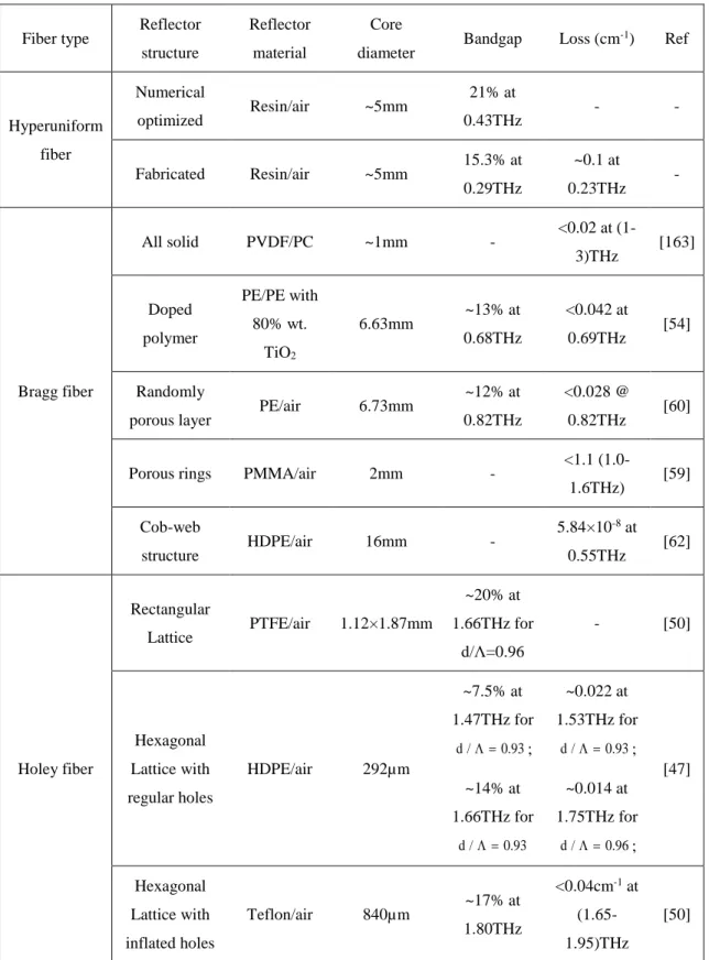
Table 3 Comparison of the bandgap widths and losses of the hollow core fibers featuring different reflector types. ... 52
Table 4 The experimental producers and solutions used in the waveguide metallization ... 84
Table 5 SNR values of the measurements with different integrated time constant ... 101
LIST OF FIGURES
Figure 1.1 (a) The power attenuation caused by transmission losses and (b) the maximum date rate limited by the dispersion for the transmission fiber with length of 10cm (blue), 1m (red), 10m (yellow), and 100m (black). ... 3 Figure 2.1 (a) Time-domain electric field waveforms detected with the receiver 3mm above and 3mm below the waveguide. (b) and (c) Experimentally mapped and numercial calculated spatial profile of the electric field obtained by moving the THz receiver in a plane perpendicular to the waveguide axis. (c) THz waveforms measured after 4 cm (black) and 24 cm (red) of propagation distance along the wire. (d) Group velocity of the propagating mode as a function of frequency. (e) The electric field amplitude attenuation coefficient of the propagating mode as a function of frequency. Reprinted from Ref [83]. ... 15 Figure 2.2 (a) Schematic of a composite fiber featuring two metal wires in a three-hole cladding. (b) Excitation efficiences and (c) absorption losses of modes guided in the two-wire-waveguide. Reprinted from Ref. [88]. (d) Schematic of waveguide with metal wire-based cladding. (d) Comparison of normalized transmissions measured by two configurations. Black solid curve and red dots are measured with the waveguide input-end face half-blocked perpendicularly and parallel to the polarization of the input THz wave, respectively. (e) Normalized near-field modal profiles of fabricated waveguide measured at frequencies of 0.31THz, 0.37THz and 0.44THz, and the simulated modal profile at 0.37THz. Reprinted from Ref. [95]. ... 16 Figure 2.3 (a) Photograph and (b) calculated fundamental guided mode structure at 1 THz of the photonic crystal fiber. Spectrogram and measured temporal profile of the THz pulse after propagation through the fiber are presented in (c) and (d). Reprinted from Ref [31]……….20 Figure 2.4 (a) Micrographs of GImPOF design 1 (left) and design 2 (right). (b) and (c) Length dependence of the bandwidth measured using sources with linewidth of 3.5nm and 0.01nm, respectively. Reprinted from Ref [106]. ... 20 Figure 3.1 Schematic of a typical stereolithography printing system ... 29 Figure 3.2 Schemas of (a) THz-TDS setup and (b) CW-THz setup for measuring the transmission of THz waveguides. For both systems, mirror assemblies, which are amounted on the movable
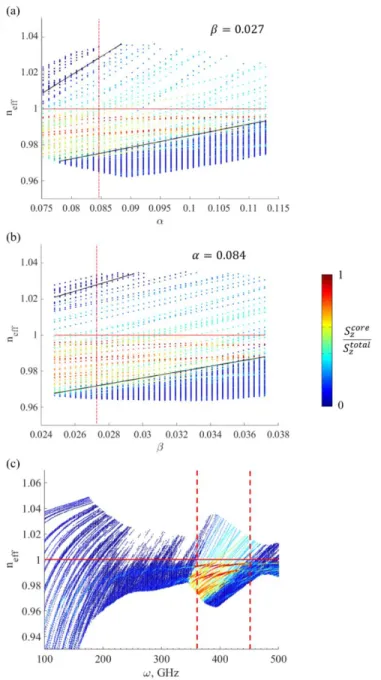
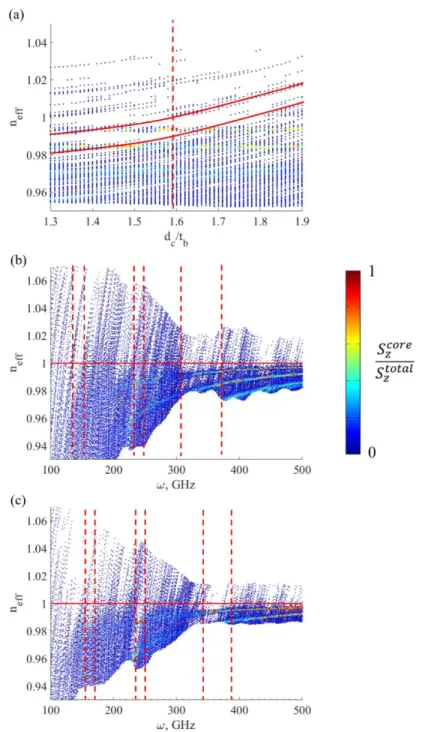
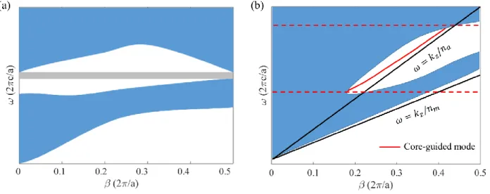
stage, can translate the output focal plane to accommodate waveguides with different lengths. Optical beams/fibers are shown in red, while the THz beams are in blue. ... 32 Figure 4.1 (a) Hyperuniform point pattern in k-space. This point pattern is used to define center positions of the dielectric cylinders in the hyperuniform PBG reflector. (b) Waveguide and a computational cell used in our numerical simulations. The reflector material is shown in blue, while the air is gray; the computational domain is terminated by a circular perfect electric conductor (PEC). The cylinder radii are 113µm and the bridge thickness is 35µm. (c) The fabricated waveguide with a bridge thickness of 200µm in the reflector. (d) Zoom of the reflector region shown in (c). (e) The fabricated waveguide with a bridge thickness of 250µm. (f) Zoom of the reflector region shown in (e). ... 38 Figure 4.2 Optimazition of the waveguide structure. (a) Sweeping 𝛼 with fixed 𝛽 = 0.027 results in an optimal value of 𝛼 = 0.084, while (b) sweeping 𝛽 with fixed 𝛼 = 0.084 results in an optimal value of 𝛽 = 0.027. The two black solid lines define the boundaries of the continuum of the cladding-bound states. The red line refers to the air light line with 𝑛 = 1. The red dashed line shows the optimal parameter value for which the air light line is positioned strictly in the middle between the two boundaries with the continuum of cladding states. (c) The band diagram of the numerically optimized waveguide structure. The red dashed lines refer to the boundaries of the bandgap centered at 0.41THz, having the width of ~90GHz. The red solid line shows the air light line. ... 39 Figure 4.3 (a) Band diagram of the numerically optimized reflector structure (a) without and (b) with the hollow core. Color of each dot indicates the fraction of power guided in the hollow core. The red circle highlights an example of the modal anti-crossing between the fundamental core guided mode and one of the surface modes. The black circles refer to different types of modes guided by the waveguide at 0.38THz. (c) Normalized longitudinal flux of different modes labelled by black circles in (b). A and F: states of the reflector continuum located outside of the bandgap. B and C: second order core guided mode and fundamental core guided more located inside the bandgap. D and E: surface modes guided in the bandgap and localised in the immediate vicinity of the waveguide core/reflector interface. ... 42 Figure 4.4 (a) Partial optimization of the waveguide structure with a bridge thickness of 200µm. Red solid lines refer to the boundaries of the reflector states, while the red dashed line indicates
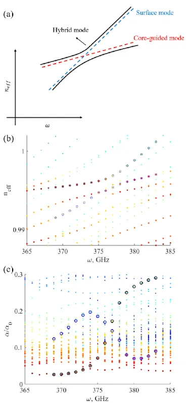
the optimal value of the cylinder diameter which maximizes the bandgap width. (b) The band diagram of the partially optimized waveguide structure with a bridge thickness of 200µm and cylinder diameter of 318µm. (c) The band diagram of the fabricated waveguide with bridge thicknesses of 200µm. ... 44 Figure 4.5 The simulated band diagrams of the fabricated waveguides with bridge thickness of (a) 200µm and (b) 250µm. (c) and (d) are the corresponding relative losses of all the modes of the two fabricated waveguides. The color code of the dots in (a) - (d) is the same as in Fig. 4. Experimentally measured transmission spectra of the waveguide with (e) 200µm and (f) 250µm. ... 47 Figure 4.6 Schematic of the band diagram for (a) 2D planar photonic crystal waveguides and (b) quasi-3D photonic crystal fibers. ... 49 Figure 4.7 (a) Schematic of the modal anti-crossing of the core-guided mode (red dashed line) and the surface mode (blue dashed line). The black solid lines refer to the dispersion relations of the hybridized modes. (b) Dispersion relations and (c) losses of the modes in the area highlighted by the red circle in Figure. 4.3(b). Two hybridized modes are labelled by black circles and blue circles, respectively. The color code of (b) and (c) are the same as that shown in Figure. 4.3. ... 51 Figure 4.8. Optical characterization of the reflector material using cutback method and four
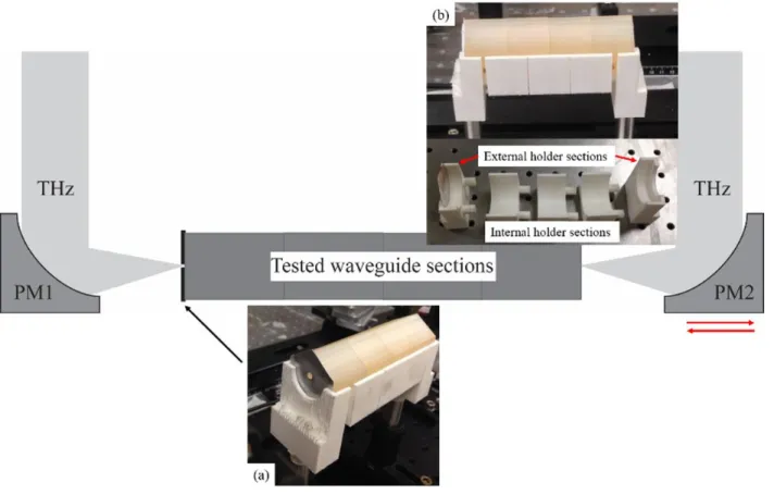
1mm-thick slices of the VisyJet® Crystal resin. (a) Normalized transmission spectra, (b) corresponding unwrapped phases, (c) the absorption coefficient and (d) the real part of the reflective index. ... 56 Figure 4.9. Schematic of the experimental setup with all of four waveguide sections mounted inside of a composite holder. Insert (a): the input facet of a waveguide features an aperture with the size equal to that of the waveguide hollow core. Insert (b): the 3D printed composite holder with sections before (bottom) and after (top) being insert into the experimental setup. PM1 – fixed parabolic mirror with a focus at the waveguide input edge. PM2 – movable parabolic mirror which is displaced every time the waveguide section is removed in order to keep the focal point at the waveguide output edge. ... 58
Figure 4.10. Experimentally measured electric field THz traces of the two waveguide with bridge thickness of (a) 200µm and (b) 250µm. Colors of the lines refer to waveguides of different length. ... 59 Figure 5.1 Modal propagation properties of the dielectric THz fibers. Blue lines correspond to the fundamental mode of the fiber, red and green lines – to higher order modes. ... 63 Figure 5.2 (a) The schematic representation and (b) the theoretical index profile of the designed GI-mPOF. The dots correspond to the localized refractive index at each layer, while the solid line is the theoretical index profile calculated using Eq. (5.2). The cross-sections of (c) GI-mPOF (outer diameter OD = 1.35mm) and (d) GI-mPOF (OD = 1.47mm). ... 67 Figure 5.3 The modal refractive indices and the group velocities of the proposed GI-mPOF and the traditional mPOF. The dots’ colors represent the logarithmic flux coupling coefficient of each mode at the given frequency. ... 69 Figure 5.4 The coupling efficiency by power for (a) the proposed GI-mPOF and (b) the traditional mPOF ... 71 Figure 5.5 (a) The individual mode dispersion and (b) the intermodal dispersion of the two fibers. The red solid lines are the dispersion properties of the proposed GI-mPOF, while the black lines show that of the traditional mPOF. ... 71 Figure 5.6 Experimental setup with the fiber mounted in the apertures. ... 72 Figure 5.7 (a) The time-domain traces of the THz electric field measured at different fiber lengths of the proposed GI-mPOF (left) and the traditional mPOF (right). The black trace represents the THz field after propagating a short distance in the fiber; the red trace represents a longer distance, and the blue trace is for the whole fiber. The initial lengths of the fibers used in the experiment are about 20 cm. (b) Mode profiles simulated at 0.5 THz for these two fibers... 73 Figure 5.8 The comparison between measured pulse and reconstructed pulse for (a) the GI-mPOF with 6.48 cm length and (b) the mPOF with 5.74 cm length. The black solid line represents the experimentally measured electric trace, while the red dot line corresponds to the reconstructed pulse based on the simulation results. ... 74
Figure 5.9 The pulse duration of the designed GI-mPOF (black) and the mPOF (red). Dots - experimental results. Dashed lines - results of the fitting based on Eq. (5.7). Solid lines – pulse duration calculated based on the reconstructed pulses. ... 75 Figure 5.10 Electric field amplitude as measured by the THz-TDS setup for the case of (a)
GI-mPOF and (b) GI-mPOF... 76 Figure 6.1 Dispersion relations of (a) metal tube and (b) hollow core waveguide Bragg grating. Black line: fundamental mode; red line: first higher order mode. ... 81 Figure 6.2 (a) The 3D geometry of the waveguide Bragg grating. Insert: zoom of the periodic structures. (b) Cut through of the fabricated waveguide Bragg grating. (c) and (d) SEM images for the area highlighted by the red circle in (b) with magnifications of ×25 and ×10000, respectively. ... 83 Figure 6.3 Band diagram of the waveguide Bragg grating. Color refers to the modal coupling coefficient (by field) to the focused Gaussian beam of 𝑤0~2𝜆. ... 85 Figure 6.4 (a) Dispersion relations of the guided modes and (b) calculated dispersion relation of the fundamental HE11-like mode in the vicinity of 140 GHz, while (c) and (d) are that in the vicinity of 160 GHz. The gray regions refer to the single mode regime where only the fundamental HE11-like mode is excited. Color of dots is the same as that shown in Figure 6.3. ... 87 Figure 6.5 Schematic of the experimental setup for optical characterization. ... 89 Figure 6.6 (a) Measured electric fields and (b) corresponding transmission spectra of fabricated waveguides. ... 91 Figure 6.7 (a) Comparison between the experimentally measured phase (red dots) and the theoretically computed phase (black solid line). Region with different colors refer to the frequency regions mention in Figure 6.3 and 6.4. The blue circle highlights errors caused the negligible transmission within the stopbands. (b) The comparison between the experimentally measured dispersion (red solid lines) and the theoretically computed dispersion of the fundamental mode (HE11). The color code of dots is the same as that shown in Figure 6.3. 92 Figure 6.8 Schematic of the setup used for near field imaging. ... 94
Figure 6.9 Near-field microscopy images (upper row) and corresponding simulations (lower row) of the normalized output 𝑬 field profile of the waveguide Bragg grating for frequencies in the vicinity of 140GHz. The black solid circle refers to the waveguide core edge, while the dashed circle shows the region of the central area of the waveguide core without periodic structures. ... 94 Figure 7.1 Measured frequency domain spectra of (a) hollow core waveguides printed by slush of copper powder and resin, (b) hollow core waveguide printed by resin only, and (c) commercial copper tubes. (d) the measured transmission losses of the measured waveguides. ... 98 Figure 7.2 SNR analysis of (a) a typical time-domain trace and (b) corresponding frequency domain spectrum. Left ordinate: average of 25 scans (red) and their standard deviation (blue). Red ordinate: calculated SNR as the ratio of the average value to the SD. ... 100 Figure 7.3 (a) Examples of the signal and background noise measured by the CW-THz system with the integrated time constant of 100ms. (b) the computed signal to noise ratio. ... 101 Figure 7.4 (a) Terahertz field amplitude as a function of frequency measured with different opening sizes of the aperture. (c) The measured THz electric field profile as a function of the aperture opening size (red dots) and the calculated THz beam profile (red solid line) at the frequency labelled by red dashed line in (a). (c) The computed beam waist size of the THz-TDS system in the frequency range of 0.1-1.1THz. Blue solid line shows the theoretical prediction (𝑤0~2.5𝜆, with 𝑓 = 10mm and 𝐷 = 5cm). ... 103
LIST OF SYMBOLS AND ABBREVIATIONS
α Absorption loss coefficient β Mode propagation constant c Speed of light in vacuum
Cmn Modal coupling by field
D Dispersion
neff Modal effictive refractive index
Sz Longitudinal flux 𝜐𝑔 Group velocity 𝜒 Hyperuniformity λ Wavelength 𝜔 Frequency DR Dynamic range PC Polycarbonate PCs Photonic crystals PE Polyethylene
TE Transverse electric mode TM Transverse magnetic mode FPG Free space propagation GHz Gigahertz
GVD Group velocity dispersion PBG Photonic bandgap
SEM Scanning electron microscope SNR Signal to noise ratio
THz Terahertz
mPOF Microstructured polymer optical fiber HDPE High density polyethylene
LDPE Low density polyethylene PMMA Polymethyl methacrylate PTFE Polytetrafluoroethylene PVDF Polyvinylidene fluoride
CW-THz Continuous wave terahertz spectroscopy
GI-mPOF Graded index microstructured polymer optical fiber THz-TDS Terahertz time domain spectroscopy
CHAPTER 1
INTRODUCTION
The terahertz (THz) range, with frequencies between 0.1 THz and 10 THz, or wavelengths between 3mm and 30μm, lies between the infrared and microwave bands. The utilization of this spectral range was plagued for a long time owing to the lack of efficient devices for generating and detecting terahertz radiation. In the early 1980s, the emergency of femtosecond lasers and photoconductive antennas made it possible to generate and detect terahertz pulses with picosecond duration [1]. Over the past decades, various terahertz sources [2-7] and detectors [8-11] have been proposed and investigated. The development in the generation and detection of terahertz radiation has greatly advanced the terahertz technology and inspired a great number of research efforts regarding its applications.
Terahertz radiation has great potential in various technological and scientific applications, such as high-bit rate communication [12-13], subwavelength imaging [14-15], chemical and biological sensing [16-17], spectroscopy [18-19], etc. In particular, in the low frequency spectral range where atmospheric transmission windows exist, it is expected that communications with carrier frequencies in the THz range will allow high rate data transmission superior to microwave communication [12]. Specifically, terahertz communication offers a much larger bandwidth which is more than one order of magnitude above the state-of-the-art millimetre-wave communication systems, while the orientation of terahertz communication is also better as terahertz radiation features much shorter wavelengths compared to microwave radiation. Recently, various THz communication systems with carrier frequency smaller than 0.6 THz and data transmission rate up to 100 Gbit/s have been developed and investigated experimentally [20-23].
Considering its low absorption loss and low dispersion in the terahertz regime, dry gas is the most promising medium for THz transmission [24]. As a consequence, most of the current THz communication systems are based on free space propagation (FSP). However, the applications of these THz communication systems are still limited due to inherent challenges posed by the free space propagation (FSP) modality. As terahertz radiation is highly absorbed by water vapour in the atmosphere, and scattered by dusts, clouds, and even atmosphere turbulences, the propagation of THz radiation is strongly dependent on atmospheric conditions. Moreover, THz beams rapidly diverge especially those at the lower carrier frequencies, as well as light-of-sight nature of the links. As a consequence, to realize low divergence THz beams, FSP requires the use of large beam
diameters and focusing optics that can be as big as several tens of centimeter in diameter for even short communication links of several tens of meters. Additionally, due to strong directionality of the THz beams, wireless communications access to partially blocked areas can be problematic, thus, requiring additional THz steering and routing solutions for reliable communications.
On the other hand, dielectric fibers and waveguides offer solutions to the limitations caused by free space propagation. Particularly, when propagating through sealed THz fibers and waveguides, THz radiation is isolated from the surroundings, and hence, influence of the atmospheric conditions on the communication link quality is minimized. Moreover, the majority of THz fibers and waveguides are flexible, allowing us to replace large and cumbersome optical hardwares and navigate THz radiation to even physically obstructed areas. Additionally, the flexibility of THz fibers and waveguides can be further enhanced by various geometrical designs [25]. Finally, THz fibers size is typically comparable to the wavelength of light, thus enabling highly compact communication links with small footprints. However, no such fiber- or waveguide-based THz communication system currently exists. The main culprits are high absorption and dispersion of terahertz fibers and waveguides.
When propagating through a dielectric fiber, the optical signal is invariably affected by both transmission losses and dispersion, and hence rapidly degrade in quality. To analyze the effects of losses and dispersion, I demonstrate the propagation of a terahertz signal with carrier frequency
0 in a dielectric fiber with a transmission loss 𝛼 and a dispersion 𝐷. To ease the analysis, I ignore the nonlinear effects in the fiber and assume the fiber is single mode in the vicinity of the carrier frequency
0. With the input electric field at z = 0 as 𝐸0(𝜔, 0), its propagation in the fiber can be written as [26]𝐸(𝑡, 𝑧) = ∫ 𝐸0(𝜔, 𝑜)exp [𝑖(𝛽𝑧 − 𝜔𝑡)] 𝑑𝜔 (1.1)
In the vicinity of the carrier frequency
0, the modal propagation constant 𝛽 can be expanded as𝛽(𝜔0+ ∆𝜔) = Re[𝛽(𝜔0)] +∆𝜔 𝜐𝑔 + 𝛽2∆𝜔2 2 + 𝑖 𝛼 2 (1.2) where 𝜐𝑔 = 1/𝛽1 = (𝜕𝛽/𝜕𝜔)−1 is the modal group velocity, 𝐷 = 𝜕2𝛽/𝜕𝜔2 is the modal dispersion, and 𝛼 = 2Im(𝛽) is the transmission loss.
Generally speaking, transmission losses result in power attenuation, and, consequently, reduction of the signal to noise ration (SNR). To correct this problem, I estimate the average power at the output end of a fiber-link with 𝑧 = 𝐿, which can be given as [26]:
〈𝑃(𝐿)〉 = lim 𝑇→∞ 1 𝑇∫ |𝐸(𝑡, 𝐿)| 2𝑑𝑡 𝑇/2 −𝑇/2 = 〈𝑃0〉 exp(−𝛼𝐿) (1.3) where 〈𝑃0〉 is the average power at the input end. Thus, the average output power 〈𝑃(𝐿)〉 decreases exponentially as the fiber link length L increases. In Figure 1.1(a), I demonstrate the relationship between the losses and the average output power of links with different lengths. For a fiber-link with a length of 10m, if we need to detect at least 10% of the input power, the maximum transmission loss of the fiber-link should be no bigger than 0.002cm-1. For a typical dielectric THz fiber with a transmission loss of ⁓0.01cm-1, only ~36% of the input power is left after propagating through a fiber with length of 1m.
On the other hand, dispersion in a fiber-link can chirp the delivered signal, and therefore causes signal distortion and broadens the signal duration. Hence, the achievable data rate of the fiber-link is limited. The relationship between the data rate B, dispersion D, and the maximum transmission distance Lm can be given as follows [26]:
Figure 1.1 (a) The power attenuation caused by transmission losses and (b) the maximum date rate limited by the dispersion for the transmission fiber with length of 10cm (blue), 1m (red), 10m (yellow), and 100m (black).
2 2 2 1 16 8 m L B D B (1.4)
where β2 is the group velocity dispersion (GVD) parameter related to the commonly used dispersion parameter D. For a given transmission distance, the maximum data rate is inversely proportional to the square root of the fiber dispersion, as shown Figure. 1.1(b). For a fiber-based transmission link with a length of 10m, to obtain a data rate of 40 Gbit/s, the maximum average dispersion is only 0.04ps/(THz cm). If the link is based on THz plasmonic waveguides whose typical dispersion is only 0.01ps/(THz cm) [26], the maximum transmission distance is only about 20m.
As dry gas offers the lowest absorption for terahertz frequencies, one can minimize the transmission losses of a THz fiber or waveguide by maximizing the fraction of power guided in the gaseous region. Based on this strategy, various THz fibers with low transmission losses (<0.01 cm-1) have been proposed and demonstrated in the past decade. Among these designs, one generally distinguishes subwavelength THz fibers that guide using total internal reflection (TIR) mechanism and hollow core fibers that guide using either photonic bandgap confinement or anti-resonant reflection (ARROW).
However, dispersion management for terahertz communication still remains unsolved. Note that even in the wireless links, dispersion of air at THz frequencies is 𝐷~2.5×10⁻⁴ps/(THz ∙ cm) [27], thus limiting the 100 Gbit/s wireless link to 400 m. In addition to pulse deformation due to group velocity dispersion, frequency dependent absorption loss due to water vapor will further contribute to pulse deformation. Therefore, while effects of dispersion can be modest in free space links, they are a major limiting factor in waveguide-based interconnects.
In order to counter the dispersion, one can follow two approaches. The first one is minimizing dispersion in THz fibers and waveguides. Most dielectric materials offer almost constant refractive indices in the terahertz frequency range [30]. Hence, dispersions in dielectric THz fibers and waveguides can be reduced by confining THz radiation in a solid core [31-32]. However, the applications of these fibers are limited by their high transmission losses caused by material absorption. Dispersion can also be reduced and flattened by the waveguide’s structural design. However, this has rarely been studied in the THz domain.
The other approach to solving the dispersion problem is to insert a dispersion compensator at the end of the link or a dispersion precompensator at the beginning. As the dispersions in free space and most of THz fibers and waveguides are positive, dispersion compensators are generally required to offer large dispersion over a relatively wide frequency range. Moreover, effective coupling with other optical devices and single mode operation in the target frequency range are necessary to ease the implementation of these dispersion compensators. For telecommunications, fiber Bragg gratings, that can effectively cancel the dispersion introduced by transmission fibers with the length of tens of kilometers, have been proposed [33-36]. However, dispersion compensation in the terahertz frequency range is still a challenge.
As a consequence, in order to utilize dielectric fibers in terahertz communication systems, we should minimize both transmission losses and dispersion. In this thesis, I will explore several types of dielectric waveguides for the manipulation of terahertz light. More precisely, I will firstly present a hollow core waveguide featuring hyperuniform reflectors, which can result in sizable bandgaps which are comparable to the best record of its counterparts with periodic reflectors based on photonic crystals. Then, I will demonstrate the design and characterization of a porous fiber featuring an air-hole array with gradually varied diameters and inter-hole separations. This fiber has been proved to be promising for terahertz guidance with both low loss and low dispersion. At last, I will show a periodically microstructured hollow core waveguide which can be used to compensate the positive dispersion of a fiber-based transmission link. To my best knowledge, this is the first time that waveguide-based dispersion compensation has ever been investigated in the terahertz domain. The following paragraphs outline the detailed organization of this thesis:
Chapter 2 begins with a literature review of terahertz fibers with reduced losses. I compare their optical properties based on their guiding mechanisms. In Chapter 2.2, I also review studies on dispersion management, including dispersion flattening and compensation. As dispersion management continues to be a challenge and has not yet been investigated in depth at terahertz frequencies, I will focus on dispersion managing fibers in the visible and infrared range.
Chapter 3 provides the methodology of my study, which follows the procedure of geometrical design based on numerical simulations, waveguide fabrication using different technologies, and optical characterization using both terahertz time-domain spectroscopy (THz-TDS) and terahertz continuous-wave (THz-CW) spectroscopy.
Chapter 4 is based on my paper “3D Printed Hollow-Core Terahertz Optical Waveguides with Hyperuniform Disordered Dielectric Reflectors” published in Advanced Optical Material in 2016. This paper focuses on the study of the utilization of hyperuniform reflectors to produce hollow core waveguides with sizable bandgaps in the terahertz range and includes detailed description of the fabrication and characterization techniques.
Chapter 5 is based on my paper “Graded index porous optical fibers – dispersion management in terahertz range” published in Optics Express in 2015. In this chapter, I present the theoretical and experimental works concerning the management of the intermodal dispersion using a porous fiber in the terahertz range.
Chapter 6 is based on my paper “Dispersion Compensation for Terahertz Communication Using 3D Printed Hollow Core Waveguide Bragg Grating” submitted to Optics Express in 2017. In this chapter, I present the design of a waveguide Bragg grating which can produce a single mode operation range in the vicinity of 140GHz and provide large negative dispersion. The optical characterization of the fabricated waveguide is also presented and discussed.
Finally, a general discussion of the achieved results and future research perspectives are presented.
CHAPTER 2
LITERATURE REVIEW
2.1 Terahertz waveguide with reduced losses
Terahertz radiation can penetrate through a majority of dielectric materials, however, the propagation length is limited by material absorption. For instance, the typical absorption losses of amorphous material suitable for THz fiber fabrication (such as glasses and polymers) are in the range of 0.1-0.3 cm-1, leading to cm-scale maximum propagation lengths. As the lowest absorption loss for THz wave occurs in dry gases, the transmission losses of the THz fibers can be reduced significantly by maximizing the fraction of the THz power guided in the low-loss gas. Based on this strategy, various THz waveguides and fibers have been proposed. According to the guiding mechanics, these waveguides/fibers can be divided into three categories, including index dielectric guiding waveguides/fibers, hollow core dielectric waveguides/fibers, and hybridized waveguides/fibers.
2.1.1 Index guiding dielectric waveguides/fibers
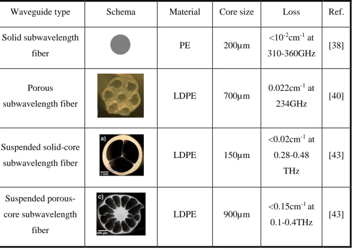
The simplest optical fibers are step index fibers, which comprises of a dielectric core surrounded by a lower refractive index medium. For these fibers, optical light is confined in the dielectric core owing to the total internal reflection, and hence, these fibers can also be named as index guiding fibers. However, the losses of such fibers are almost the same as that of the material absorption. In the optical domain, reducing the fiber core size to the subwavelength scale has proven to be an efficient method for low-loss guidance [37]. The first subwavelength fiber in the THz regime was demonstrated by Chen el al [38]. They used a polyethylene (PE) wire with a diameter of 200 µm for THz guidance. As the guided model field extends far into the air cladding, the attenuation constant of this fiber can be reduced to 0.01cm-1. Later, researchers [39-42] discovered that introducing an array of deeply subwavelength holes into the core of a subwavelength fiber enabled further reduction of both the absorption and bending losses, and broadening of the transmission bandwidth.
In subwavelength fibers, the propagation loss is reduced due to low modal confinement in the lossy, solid-core region. However, the mode of subwavelength fibers is significantly affected
by its environment thus preventing direct manipulation of such fibers. In order to solve this problem, Roze et al. [43] proposed the suspension of the subwavelength cores inside of polymer tubes. The presence of the outer cladding provides good protection for the guided mode, thus reducing sensitivity to environmental changes. Because of weak confined model fields, this type of subwavelength fiber has great potential for bio-sensing applications [44]. Nevertheless, the application of subwavelength fibers in terahertz communications is still limited by their significant group velocity dispersions (GVDs) as these fibers typically operate in a frequency range where the guided mode confinement changes dramatically from weak confinement (high presence in the gaseous cladding) at low frequencies, to strong confinement (high presence in the solid core) at high frequencies.
Table 1: The comparison between different types of subwavelength fibers for terahertz guidance.
Waveguide type Schema Material Core size Loss Ref.
Solid subwavelength
fiber PE 200µm
<10-2cm-1 at
310-360GHz [38]
Porous
subwavelength fiber LDPE 700µm
0.022cm-1 at
234GHz [40]
Suspended solid-core
subwavelength fiber LDPE 150µm
<0.02cm-1 at 0.28-0.48 THz [43] Suspended porous-core subwavelength fiber LDPE 900µm <0.15cm -1 at 0.1-0.4THz [43]
2.1.2 Hollow core dielectric waveguides/fibers
Besides the fibers mention above, low-loss guidance in the terahertz domain can also be achieved by guiding light in a gaseous core. Based on this strategy, various waveguides utilizing different guiding mechanisms, including photonic bandgap (PBG) guidance and anti-resonant reflective guidance, have been proposed.
2.1.2.1 Photonic bandgap waveguides
Typically, hollow core PBG waveguides feature a gaseous core surrounded by dielectric periodic reflectors formed by periodic refractive index variation. Due to the photonic bandgap effects, at frequencies within the photonic bandgaps, optical light cannot pass though the dielectric reflector, and the majority of power is guided as the core guided mode with ultralow losses. Hence, frequency dependent photonic bandgaps are formed. Within these bandgaps, as terahertz radiation is confined in the gaseous core, the transmission losses are negligible. Moreover, the transmission properties of these waveguides, including the transmission bands and dispersion characters, can be tuned simply by varying the geometrical parameters of the reflector. Various hollow-core PBG fibers based on the photonic bandgap effect have been proposed for terahertz guidance with low-losses. These fibers can be sorted into two categories, holey fibers and Bragg fibers, depending on their reflector structure.
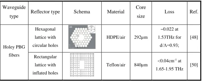
In the case of holey fibers, the reflector in the cladding is usually formed of a 2D photonic crystal with periodically positioned holes. Only in the bandgap of the reflector can modes be confined and propagate through the core. These fibers are proposed primarily for guidance in the optical domain [45-46]. However, these fibers suffer from the relative high confinement losses due to the infinite layers of holes in the cladding. When expanded into the terahertz domain [47-51], the modal leakage does not harm the guidance of light. Vincetti et al. [47] showed that a holey reflector with only three layers of air-holes was good enough to confine the majority of power in the core, and produced a confinement loss of 0.0002 cm-1 which is negligible compared to material absorption (0.01cm-1) in the same frequency range. Owing to the PBG effect, various periodic lattices such as, triangular [47-49], rectangular [50], and honeycomb [51-53], to name but a few., can be used as the reflector of holey fibers. The key parameter of these periodic lattices is the air filling fraction, or the air-hole diameter to hole-to-hole pitch ratio (𝑑/Λ), in the cladding, which
determines both the spectral position and width of the bandgaps. Holey PBG fibers with high air-filling fractions are usually designed for wider bandgaps.
Bragg fiber is another type of hollow PBG fibers used for terahertz guidance. It exploits resonant reflection from a periodic multilayer reflector with circular symmetry surrounding the hollow core region. To produce photonic bandgaps, hollow core Bragg fibers usually feature alternative layers to achieve a periodic variation of the refractive index in the radial direction. The simplest Bragg reflector can be formed by repeating alternate concentric layers of two different polymers. A hollow core Bragg fiber with this kind of reflector was first theoretically demonstrated by Skorobogatiy et al. [54] in 2007. The transmission of losses less than 0.2cm-1 over a wide frequency range (1-3THz) was accomplished using an all-polymer multilayer structure (PVDF/PC) as the reflector. However, one should note that the wide, low-losses transmission range was attributed to the relatively large refractive index contrast between PVDF and PC, particularly in the frequency range of 0.6-2.0THz where the refractive index of PVDF is even smaller than that of the air. The proposed waveguide is not easily fabricated in the lab due to the differing thermal and mechanical properties of PVDF and PC. It is hard to find dielectric materials with both large refractive index contrast and similar thermal and mechanical properties, which are required by the fiber drawing technology [55-56]. To solve this problem, another type of all-solid Bragg reflector was proposed by using the same material with different dopants [57-58]. In [58], the authors proposed a hollow core Bragg fiber using the PE and TiO2-doped PE based multilayer structure. Through the control of dopant concentration, the refractive index contrast in the Bragg reflector can easily be tuned. Low transmission losses below 0.1cm-1 are attainable in such fibers.
As with all-solid Bragg fibers, several techniques using porous Bragg fibers have been reported, which involve the introduction of rings of porous material. The simplest porous Bragg fiber was fabricated by introducing air-holes to the cladding [59]. The proposed porous Bragg reflector consisted of five circular rings of air-holes. The presence of these air-holes reduced the effective refractive index of porous layers, and Bragg reflections occur at the interface between layers with and without air-holes. Using this fiber, a low transmission loss of ~1.1cm-1 was attained over a range of 0.8-1.4THz. To enlarge the PBG width, hollow core Bragg fibers with solid/randomly porous multilayers [60] and cob-web structures [61-62] were investigated in the terahertz range. For these fibers, a high refractive index contrast was realized due to ultra-high porosities in the cladding, thus allowing low-loss transmission over a broad spectral range. For
example, in the case of a hollow core Bragg fiber with a cob-web reflector, the transmission losses of the fundamental mode were theoretically predicted to be as low as < 1.9×10⁻⁵cm-1 over 0.3-4.3THz [61]. However, Bragg fibers with ultra-high porosities in their cladding are not easily fabricated, as their structures are extremely fragile.
2.1.2.2 Anti-resonant reflecting fibers
In addition to photonic bandgap guidance, anti-resonant reflecting guidance can also be used to confine terahertz radiation within a core having low refractive index. For fibers based on anti-resonant (ARROW) guidance, both the core and the cladding can support guided modes, and the core-guided modes are guided in the core region owing to the anti-resonant Fabry-Perot (F-P) effect [63]. The simplest ARROW fiber is a dielectric pipe with a thin wall [64], where the thin dielectric wall acts as a Fabry-Perot resonator. Transmission with high modal confinement in the core region and ultra-low transmission losses occurs at the anti-resonant frequencies of the F-P reflector. ARROW guidance in the terahertz domain was first demonstrated by Lai el al. [65], where PMMA pipes with differing wall thicknesses were characterized. The experimental results confirmed that transmission bands, corresponding to the frequencies between two adjacent resonant frequencies, can be tuned by varying the refractive index and thickness of the dielectric wall.
The Kagome hollow core waveguide is another waveguide based on ARROW guidance. The reflector structure of this waveguide gives the appearance of a kagome structure, which is a traditional Japanese woven bamboo pattern. Although both the core and cladding support guided modes, core-guided modes are prevented from coupling to the cladding due to the anti-resonant reflecting of the Kagome lattice in the cladding [66-67]. Compared to their counterparts using PBG reflectors, Kagome hollow core waveguides can have a much wider transmission band. However, transmission losses within bandgaps are much higher than that of hollow core PBG fibers.
The first Kagome hollow core waveguide for THz guidance was experimentally demonstrated by Lu et al. [68]. The waveguide reflector was fabricated by packing Teflon tubes in the hexagonal closest packed arrangement around a gaseous cavity. The outer diameters of the fabricated waveguides were in the cm-scale. A low attenuation loss of less than 0.002cm-1, which is a negligible loss when compared to the material absorption of Teflon, was attainable for the proposed waveguide at 0.77THz. Moreover, the bandgap guidance was shown to be adjustable by
linearly scaling the whole waveguide size, including the inner diameter of the hollow core and the outer diameter of the whole waveguide. Hollow core Kagome waveguides with reduced sizes were also proposed by Anthony et al. [69]. A preform with an outer diameter of 80mm was first fabricated by stacking PMMA tubes in a triangular lattice, and then stretched into Kagome waveguides with the desired outer diameters of 5 mm and 6.8 mm, respectively. In this experiment, attenuation losses 20 times lower than that of the material absorption were achieved over a wide range of frequencies, 0.75-1.0 THz and 0.6-1.0THz, respectively.
Furthermore, numerical investigations [70-71] showed that both the attenuation losses and bandgaps could be tailored through the adjustment of geometric parameters of the waveguide. Specifically, the attenuation losses can easily be reduced by increasing the size of the hollow core, while reducing the thickness of the struts in the cladding can not only broaden the bandgap width but also flatten the dispersion relation of guided modes with bandgaps.
Both the photonic bandgap guidance and anti-resonant reflecting guidance can be used to reduce the transmission losses effectively. However, the potential applications of these hollow core fibers are limited by their own inherent drawbacks. To begin with, as we can see in Table 2, most of these fibers have large dimensions, rendering them inflexible. However, transmission losses are inversely proportional to the core size as α~𝑑𝑐𝑜𝑟𝑒−3 where 𝑑𝑐𝑜𝑟𝑒 is the core diameter [78]. Thus, a relative large core is necessary for low-loss transmission. A large core size would also lead to multimode guidance, and consequently, the intermodal interactions, such as modal anti-crossing and intermodal dispersion, would be pronounced.
Table 2 The comparison between different types of hollow core fibers for terahertz guidance. Waveguide
type Reflector type Schema Material
Core
size Loss Ref.
Holey PBG fibers Hexagonal lattice with circular holes HDPE/air 292µm ~0.022 at 1.53THz for d/Λ=0.93; [48] Rectangular lattice with inflated holes Teflon/air 840µm <0.04cm -1 at 1.65-1.95 THz [50]
Honeycomb lattice Topas/air ~1mm ~0.058cm-1 at 0.98THz [52] Bragg fibers All-solid Bragg reflector PVDF/PC ~1mm <0.02cm-1 at 1-3 THz [54] All-solid Bragg reflector with doped polymer PE/PE with TiO2 dopants 6.63mm <0.042cm -1 at 0.69THz [57] Bragg reflector with porous layers PMMA 2mm <1.1cm -1 at 1.1-1.6 THz [59] Bragg reflector with randomly porous layers PE/air 6.73mm <0.028cm -1 at 0.82THz [60] Bragg reflector with Cob-web structure HDPE/air 16mm 5.84×10 -5cm-1 at 0.55THz [61] ARROW fibers Tubes with thin dielectric walls Teflon 9mm 0.0008cm -1 at 375GHz [65] Kagome fibers with thick struts Teflon/are 5mm 0.002cm -1 at the 770GHz [68]
Kagome fibers
with thin struts PMMA/air 2.2mm
0.6 cm-1 at 0.65-1.0 THz [69] Tube lattice fiber PMMA/air 1.62mm <0.01cm-1 at 0.78-0.90THz [72]
2.1.3 Hybrid waveguides/fibers
The earlier forms of THz waveguides were metallic in nature with a circular or rectangular hollow core [72-74]. However, these waveguides suffered from very high transmission losses due to high Ohmic losses in metals, which is caused by the fact that electric radiation does not vanish entirely on the metal/air interface, but penetrates into the metal by several nanometers (also known as the skin effect). Thus, the typical transmission loss of a metallic hollow core waveguide is in the scale of 1 cm-1 [72], not to mention their high dispersion close to cut-off frequencies.
Current research [75-81] shows that the transmission losses of metallic hollow core waveguides can be reduced by adding a thin dielectric layer on the inner surface of these metal waveguides. Apart from the reduced losses, these dielectric-coated waveguides support two modes with low-loss characteristics, the hybrid HE11 mode or the transverse TE01 mode [76,78,82]. Moreover, the dominant mode can be selected through the geometric properties of the waveguide, include the core size and the coated layer thickness [76]. For instance, when the coated dielectric layer is thick (~10 µm), the HE11 exhibits a lower loss, while the TE01 mode is suppressed. Conversely, in the waveguide with a dielectric layer of several micron or even thinner, the TE01 mode is less lossy, while the HE11 mode is restrained.
In addition to these metallic hollow core waveguides with dielectric coating, various waveguides based on metal wires have been proposed for low-loss guidance in the terahertz domain. Such guidance was firstly proposed based on a stainless steel wire with a diameter of 0.9mm, with which both low loss (<0.03cm-1 over the frequency range of 0.25-0.75THz) and negligible group velocity dispersion were realized [83]. However, as the fundamental mode in single-wire- based waveguides is radially polarized, it is very difficult to be excited with the
Figure 2.1 (a) Time-domain electric field waveforms detected with the receiver 3mm above and 3mm below the waveguide. (b) and (c) Experimentally mapped and numercial calculated spatial profile of the electric field obtained by moving the THz receiver in a plane perpendicular to the waveguide axis. (c) THz waveforms measured after 4 cm (black) and 24 cm (red) of propagation distance along the wire. (d) Group velocity of the propagating mode as a function of frequency. (e) The electric field amplitude attenuation coefficient of the propagating mode as a function of frequency. Reprinted from Ref [83].
linearly polarized THz light produced by photoconductive antennas. To make matters worse, terahertz guidance along single wire waveguides suffers from enormous bending losses due to poor modal confinement [84].
To overcome these difficulties, THz guidance along two parallel metal wires was investigated [85-92]. In these waveguides, the fundamental mode is linearly polarized along the line connecting the two wires, which allows the direct excitation of the guided mode with a majority of THz sources. Also, as terahertz radiation propagates through the air-gap between the two wires, the modal confinement of these two-wire-based waveguides are enhanced, and hence the bend
Figure 2.2 (a) Schematic of a composite fiber featuring two metal wires in a three-hole cladding. (b) Excitation efficiences and (c) absorption losses of modes guided in the two-wire-waveguide. Reprinted from Ref. [88]. (d) Schematic of waveguide with metal wire-based cladding. (d) Comparison of normalized transmissions measured by two configurations. Black solid curve and red dots are measured with the waveguide input-end face half-blocked perpendicularly and parallel to the polarization of the input THz wave, respectively. (e) Normalized near-field modal profiles of fabricated waveguide measured at frequencies of 0.31THz, 0.37THz and 0.44THz, and the simulated modal profile at 0.37THz. Reprinted from Ref. [95].
losses, as well as the modal leakage, are suppressed. Moreover, the characteristics of the guiding modes are dependent on the waveguide geometry, in particular, the size of the air-gap between two wires. When the displacement of these two wires is comparable to the wavelength of guided light [90], plasmonic modes are excited because of the presence of metal wires, and the dielectric cladding functions as a mechanical support. When the air-gap between the two wires is much bigger than the wavelength of guided light [93], the fundamental mode become a HE11-like mode supported by ARROW guiding. In this case, the dielectric cladding of the two-wire-based waveguide works as an ARROW reflector, just as the thin-walled dielectric tubes shown in Section
1.1.2, while the metal wires are used to prevent the guided light from dispersing into the dielectric cladding with high absorption.
Apart from these two-wire-based THz waveguides, hollow core waveguides featuring wire metamaterial-cladding were also proposed to guide THz radiation [95-98]. Owing to its extreme anisotropy, uniaxial metamaterials reflects transverse magnetic (TM) waves and transmits transverse electric (TE) waves. As a result, hollow core waveguides, produced through the arrangement of wire metamaterials in the cladding, only support TM mode, which halves the number of guided modes available and enlarges the single mode range. Based on this principle, Li et al. [97] proposed a metamaterial-based hollow core waveguide by embedding indium wires in the cladding. The aforementioned waveguide supports single mode (TM1) guidance over a frequency range of 0.29–0.44THz, and the transmission losses within the single mode range have been experimentally confirmed to be as low as ~0.06cm-1.
2.2
Optical-fiber-assisted dispersion management
To date, various dielectric waveguides have been proposed for low-loss guidance in the terahertz range. However, dispersion continues to be a challenge. Some fibers with reduced losses, such as subwavelength fibers, even make the dispersion problem worse. Other fibers, such as the metal wire and Kagome fibers, support simultaneously low-loss and low-dispersion guidance. However, due to their own deficiencies, such as the poor coupling of SPP modes of metal wires and the brittle structure of Kagome fibers, the use of these fibers is still problematic. However, in the visible and infrared regimes, dispersion management has been investigated in-depth and various remedies employing the assistance of optical fibers have been reported. In fact, occupying a position adjoining visible and infrared light in the electromagnetic spectrum, the terahertz field often borrows the ideas and methods already implemented in the optical domain. In this section, I will review some notable examples of optical fibers for dispersion management in the visible and infrared regimes, which may be adequate for similar applications in the terahertz range. In the following paragraphs, I will classify these fibers into two categories based on their functions, including dispersion flattened fibers and dispersion compensating fibers.
2.2.1 Dispersion reduced fibers
For optical fibers, dispersion represents a broad class of phenomena related to group velocity variation of the guided electromagnetic wave, including frequency-dependent material dielectric constants, frequency-dependent group velocity, and group velocity difference between different modes. Based on these mechanisms, the different types of dispersion can be distinguished as material dispersion, waveguide/individual dispersion and intermodal dispersion. In the terahertz regime, the majority of dielectric materials suitable for waveguide manufacture, such as most polymers and silica, feature frequency-independent dielectric constants, resulting in negligible material dispersions. Thus, in this part, I will place a greater emphasis on waveguide dispersion and intermodal dispersion management.
Waveguide dispersion, also known as group velocity dispersion (GVD), is a phenomenon behind the frequency-dependent group velocity (𝜐𝑔). This term can also be defined by the derivative of the inverse group velocity with respect to the angular frequency, namely
GVD = 𝜕 𝜕𝜔 1 𝜐𝑔 = 𝜕 2𝛽 𝜕𝜔2 (2.1) where 𝛽 is the modal propagation constant. As the modal field distribution intensively impacts the value of 𝛽, we can expect flattening waveguide dispersion based on the geometric design of the waveguide. With this in mind, various optical fibers have been proposed for providing tiny (near-zero) and ultra-flattened dispersion in a broadband spectral range. Among these fibers, the solid-core photonic crystal fiber (PCF) is the most promising one.
Unlike the hollow core photonic crystal waveguides shown in Section 2.1.2, by introducing a solid defect to the center, the solid-core photonic crystal fibers guide optical light using index guiding based on the total internal reflection (TIR) [99-100]. In these fibers, optical light is confined in the solid core, and isolated from the outmost air-hole-layers and surrounding environments by the first layers of air-holes. The geometry of the air-holes in the cladding is not essential to the confinement of light being guided in the core region, but can be used to modify the characteristics of guided modes.
Using this strategy, various photonic crystal fibers (PCFs) have been proposed to manage waveguide dispersion. In these PCFs, the dispersion can be flattened or shifted by simply changing