HAL Id: hal-01701684
https://hal.archives-ouvertes.fr/hal-01701684
Submitted on 4 Dec 2019
HAL is a multi-disciplinary open access
archive for the deposit and dissemination of
sci-entific research documents, whether they are
pub-lished or not. The documents may come from
teaching and research institutions in France or
abroad, or from public or private research centers.
L’archive ouverte pluridisciplinaire HAL, est
destinée au dépôt et à la diffusion de documents
scientifiques de niveau recherche, publiés ou non,
émanant des établissements d’enseignement et de
recherche français ou étrangers, des laboratoires
publics ou privés.
Transmission electron microscopy study of precipitate
morphology and precipitate overcoming processes in
aluminum alloy 6056 T6
Marie Vivas, Philippe Lours, Christophe Levaillant, Alain Couret, Marie-José
Casanove, Armand Coujou
To cite this version:
Marie Vivas, Philippe Lours, Christophe Levaillant, Alain Couret, Marie-José Casanove, et al..
Trans-mission electron microscopy study of precipitate morphology and precipitate overcoming processes in
aluminum alloy 6056 T6. Materials Science and Engineering: A, Elsevier, 1997, 234, pp.664-667.
�10.1016/S0921-5093(97)00274-8�. �hal-01701684�
Transmission electron microscopy study of precipitate morphology
and precipitate overcoming processes in aluminum alloy 6056 T6
M. Vivas ‘, P. Lours a, C. Levaillant a, A. Couret b,*, M.J. Casanove b, A. Coujou b
a Ecole des Mines d’Albi-Carmaux, Campus Jarlard, route de Teillet, 81013, Albi Cedex 09, France b CEMES, 29 rue J. Marvig, BP 4347, 31055, Toulouse Cedex, France
Abstract
High resolution electron microscopy and in situ straining experiments are performed on aluminum alloy 6056 T6 to charaterize the morphology of precipitates and the processes of precipitate overcoming by the dislocations. Two types of precipitates (needles and laths) are identified. They are found to be sheared by the dislocations and the maximum force precipitates can sustain before being sheared is calculated.
Keywords: Aluminum alloy 6056 T6; Precipitate morphology; Precipitate shearing; In situ straining experiments
1. Introduction
Aluminum alloys of the 6000 series are now attract- ing a great deal of interest for the design of aircraft fuselage skin. Simultaneous improvement of the me- chanical strength and the corrosion resistance of those alloys is however still required. The flow stress of alloy 6056 T6 slowly decreases from - 196°C (375 MPa) to 125°C (305 MPa) then drops dramatically beyond this temperature [l]. In this type of alloy, strengthening results from the interaction of dislocations with fine precipitates promoted by T6 tempering. Strengthening
models include parameters such as the volume fraction
of precipitates, the distribution of precipitates in the slip plane of dislocations and the maximum force pre- cipitates can sustain before being sheared by disloca- tions [2,3]. In this context, the general aim of this study is to investigate the mechanical properties of the precip- itation hardening alloy 6056 T6 using a microscopic scale approach and to correlate those properties to the microstructure of the material. A special attention is paid to the determination of two key ingredients: The distribution and morphology of precipitates in the slip planes as well as the processes of precipitate overcom- ing by the dislocations.
* Corresponding author. Tel.: + 33 5 62257871; fax: + 33 5 62257999; e-mail: [email protected]
0
2. Experimental details
Table 1 gives the chemical composition of alloy 6056. The alloy is solution treated at 55O”C, water quenched and tempered at 175°C during 8 h. High resolution electron microscopy (HREM) and in situ straining ex- periments [4] have been performed on 6056 T6 poly- crystalline specimens kindly provided by PCchiney CRV.
3. Experimental results
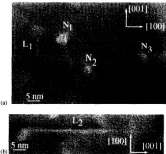
Fig. 1 shows two HREM
pictures of different zones of the same specimen. Fig. l(a) shows several precipi- tates: Some of them (noted N,, N, and N3) have a roughly circular cross-section with a diameter of about 2-4 nm and another one (noted L,) has a roughly rectangular cross-section lying along the [OOl] direction of the aluminum matrix. In Fig. l(b), a longer precipi- tate L, (46 nm) is seen. It is elongated along the [OOl] direction of the aluminum matrix.Fig. 2 shows a deformation sequence issued from a TEM in situ straining experiment performed at room temperature, which is representative of our observa- tions. In Fig. 2(a), a dislocation is pinned at several precipitates. Under the effect of the applied stress, the dislocation is bowed out between precipitates. The con-
Table 1
Chemical composition of alloy 6056 (weight %)
Al Si MI% cu Mn Fe Zn Zr Balance 0.943 0.869 0.798 0.634 0.198 0.153 0.11 Cr 0.066 Ti 0.039
trast of the dislocation vanishes in the vicinity of the precipitates, owing to a compensation effect between the dislocation and the precipitate strain fields. This is particularly obvious in Fig. 3 taken under weak beam condition at larger magnification. Between Fig. 2(a) and (b), segment S, escapes from precipitate P,. Be- tween Fig. 2(b) and (c), the dislocation escapes from all the precipitates on which it is pinned, glides quickly and stops at the position shown in Fig. 2(c). These two positions of the dislocation are seen on two successive frames of our video tape, indicating that all this move- ment occurs in less than l/50 s. Between Fig. 2(c) and (d), only a part of the dislocation escapes from the precipitates on which it is pinned.
Fig. 2 shows thus that the dislocations overcome the precipitates by a shearing process. To calculate the critical force corresponding to this process it is neces- sary to measure the breaking angles corresponding to the critical position at which the obstacle breaks [5]. Fig. 3, showing a dislocation in critical position just before it shears a precipitate, displays an example of such a determination. T, and T2 are tangent vectors to the dislocation line at points A and B, where the dislocation is in contact with the precipitate. p1 and /I2 are the angles between the Burgers vector of the dislo- cations and T, and T2, respectively. Values are subse- quently corrected taking into account both the specimen tilt angle and the inclination of the slip plane
Fig. 1. HREM images of precipitates.
with respect to the foil plane to give the true values of angles.
4. Discussion
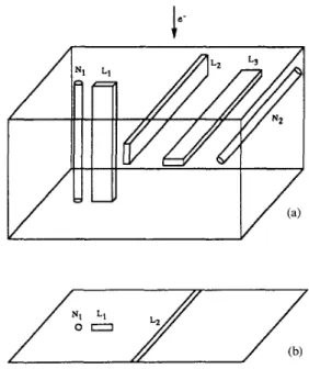
HREM pictures show precipitates with circular or rectangular cross-sections, with characteristic dimen- sion in the range of 2-5 nm, and very elongated precipitates with the length in the range of 40-120 nm. Conventional transmission electron microscopy (TEM) pictures taken at an intermediate magnification show that the present observations reproduce well the precip- itate population of the 6056 T6 aluminum alloy [5]. The number of elongated precipitates is smaller than that of circular and rectangular ones. These results are inter- preted as follows (Fig. 4). Precipitates with circular (N,) and rectangular (L,) cross-sections are needles and laths seen edge on. Elongated precipitates (LJ are laths with the length of the rectangular cross-section parallel to the electron beam. Laths (LJ with the width of the rectangular cross-section parallel to the electron beam and needles (NJ with length perpendicular to the elec- tron beam can not be imaged because the quantity of matter crossed by the electron beam is not sufficient to provide a contrast on the HREM pictures especially as they are embedded in a rather thick matrix. These results are in agreement with those reporting the pres- ence of needle-shaped p” and lath-shaped L precipitates in a T6 peak aged aluminum alloy with a composition close to that of 6056 [6].
The present work shows thus that precipitates are frequently sheared by the dislocations. In few cases, formation of dislocation loops have been however ob- served (unpublished data, [ 11).
The analysis of the critical position at which the
obstacles break allows the calculation of the maximum
force precipitates can sustain by stating that the force
exerted by the dislocation on the precipitate is the resultant of the line tension T, and T2. The dependence of the line tension of a dislocation on its character is taken into account in the present calculations [5]. The line tension is calculated using the Dewitt and Koehler relation [7].
where E(P) is the line energy of dislocation per unit length.
Fig. 2. Dynamic TEM in situ straining sequence showing the shearing of precipitates by a dislocation.
Fig. 3. Image of a dislocation in critical position just before it shears a precipitate. T,, and & are the projection in the glide plane of T, and T2.
E(B)=$ cos’p+l_ [
sin* /I L
v I xLn 0 - r
with u, 29.3 GPa, shear modulus; 6, 0.286 nm, Burgers vector of the dislocation; v, 0.347, Poisson ratio; p, angle between the dislocation line and the Burgers vector, L and r the outer cut-off distance and inner cut-off radius of the elastic strain field of dislocation respectively. L is taken equal to 20 nm, the mean inter-particle distance, in our calculations.
The modulus of vector F,,, is thus:
F, = JT: + T; + 2T, T2 cos(pz - p,)
For the case displayed on Fig. 3, for which /?, = 126” and /I2 = 46”, one has T, = 0.36 nN, T, = 0.44 nN and
Fm
= 0.61 nN. The average value of our measurement is0.6
nN [5]I/
(a)
Fig. 4. Shematic representation of precipitates (a) and of the corre- sponding TEM picture (b). The notation are defined in the text.
A coherent evaluation of the critical resolved shear stress needed by the dislocation to overcome a row of precipitates can be deduced from the value of F,,, provided the volume fraction of precipitates, the mean precipitate size and the line tension are known [2,3,5]. A better correlation between the microscopic data and the macroscopic mechanical properties can be however ex- pected via the characterization of the morphology and distribution of precipitates in the glide plane in addition to the knowledge of F,. On this last point, work based on a quantitative analysis of dynamic in situ sequences and TEM post-mortem pictures with dislocations used as tracers of the presence of precipitates is in progress (unpublished data).
5. Conclusion
The morphology of precipitates in aluminum alloy 6056 T6 has been determined by high resolution elec- tron microscopy. Elongated needles and laths have been identified.
In situ deformation experiments have shown that precipitates are sheared by the dislocations. The force
corresponding to this shearing process has been calcu- lated.
References
[l] M. Vivas, P. Lotus, C. Levaillant, A. Comet, M.J. Casanove, A. Coujou, in: J.H. Driver, B. Dubost, F. Durand, R. Fougeres, P. Guyot, P. Sainfort, M. Suery (Eds.), Proceedings of the Fifth International Conference on Aluminum Alloys, Part 2, (Greno- ble: Socitte Francaise de Mttallurgie et des Materiaux, Institut National Polytechnique de Grenoble), 1996, p. 1305.
[2] L.M. Brown, R.K. Ham, in: A. Kelly. R.B. Nicholson (Eds.), Strengthening Methods in Crystals, 1971, Section 2, p. 9. [3] V. Gerold, in: F.R.N. Nabarro (Ed.), Dislocations in Solids,
1979, Section 15, p. 221.
[4] A. Couret, J. Crestou, S. Farenc, G. Moltnat, N. Clement, A. Coujou, D. Caillard, Microscopy Microanalysis Microstructures 4 (1993) 153.
[5] M. Vivas, P. Lours, C. Levaillant, A. Couret, M.J. Casanove, A. Coujou, Phil. Mag. (1997) in press.
[6] L. Sagalowicz, G. Hug, D. Bechet, P. Sainfort, G. Lapasset, in: T.H. Sanders Jr., E.A. Starke Jr (Eds.), Proceedings of the Fourth International Conference on Aluminum Alloys, Vol. I, (Atlanta, Georgia: Georgia Institute of Technology), 1994, p. 636.