UNIVERSITÉ DE MONTRÉAL
DYNAMIC MODELING OF TUBE-SUPPORT INTERACTION IN HEAT
EXCHANGERS
REZA AZIZIAN
DEPARTEMENT DE GÉNIE MÉCANIQUE ÉCOLE POLYTECHNIQUE DE MONTRÉAL
THÈSE PRÉSENTÉE EN VUE DE L‟OBTENTION DU DIPLÔME DE PHILOSOPHIAE DOCTOR
(GÉNIE MÉCANIQUE) DÉCEMBRE 2012
ii
UNIVERSITÉ DE MONTRÉAL
ÉCOLE POLYTECHNIQUE DE MONTRÉAL
Cette thèse intitulée:
DYNAMIC MODELING OF TUBE-SUPPORT INTERACTION IN HEAT
EXCHANGERS
présentée par: AZIZIAN Reza
en vue de l‟obtention du diplôme de : Philosophiae Doctor a été dûment acceptée par le jury d‟examen constitué de :
M. BALAZINSKI Marek, Ph.D., président
M. MUREITHI Njuki William, Ph.D., membre et directeur de recherche M. PETTIGREW Michel, post grad.dipl., membre et codirecteur de recherche Mme ROSS Annie, Ph.D., membre
ACKNOWLEDGMENTS
I would like to express my sincere thanks and deep appreciation to my Ph.D supervisor, Professor Njuki Mureithi and co-supervisor, Professor Michel Pettigrew. I am very appreciative of their thoughtful guidance, patience and constant support throughout my doctoral study. They have had a profound impact on the way that I approach scientific problems, find solutions and solve problems. I believe this will be very helpful for my future scientific work and also for real life problems.
I have been privileged to collaborate with members of the chair of fluid-structure interaction during my Ph.D program. I would like to thank Mr. Thierry Lafrance for his technical support and guidance during experimental tests, and for the modifications to the experimental rig, and Mr. Bénedict Besner for his guidance regarding the work with laser displacement devices, force transducers and data accusation system.
I would like to express thanks to Mr. Heung Seok Kang for his help and guidance with damping measurements, Ms. Isabelle Nowlan for sharing her experiences on tube-support experimental tests and finally Mr. Pierre Sawadogo for valuable scientific discussions.
I would like to express my appreciation to Professor Stéphane Étienne for his support and help during writing of this thesis and particularly the translation process of the “Résumé”.
I would like to thank all my colleagues and friends in the department of mechanical engineering at École Polytechnique de Montréal.
Finally, I take this opportunity to convey my profound gratitude to my beloved father, Professor J.Azizian, my mother, Ms. K.Moshiri and my sister, Dr. H.Azizian, for their encouragements and supports throughout the several years of my doctoral work.
RÉSUMÉ
Les forces induites par écoulement dans les échangeurs de chaleur peuvent provoquer des vibrations excessives et des interactions avec les supports. Avec le temps, ces interactions peuvent entraîner de l‟usure par frottement et éventuellement mener au bris des tubes. La prédiction précise de l‟interaction tube-support est importante pour quantifier l‟usure par frottement. Ainsi, l‟étude détaillée du frottement et des forces d‟impact à l‟origine de ces effets est nécessaire à l‟établissement d‟un modèle d‟usure précis. Cette étude porte sur le développement d‟un modèle de frottement qui permet de reproduire fidèlement les différents états du phénomène de frottement, incluant les effets d‟élasticité, de plasticité et de frottement partiel. Le modèle d‟impact tube-support résultant est vérifié numériquement et expérimentalement.
Un modèle de frottement fonction du taux d‟amortissement d‟un ressort hybride a été développé pour simuler précisément un phénomène de frottement d‟une vitesse nulle à une vitesse de glissement importante. Cela a été obtenu en considérant différents phénomènes pendant le phénomène de friction incluant l‟effet Stribeck, les forces variables de rupture, l‟élasticité des micro-protubérances de paroi ainsi que les comportements de glissement plastique et partiel. Le temps de glissement dans le modèle de friction à limitation de vitesse a été comparé à celui obtenu par le modèle de friction de Lugre. L‟incapacité du modèle de frottement à limitation de vitesse à détecter la zone d‟adhérence a été expliquée par la dépendance du critère de limitation de la vitesse sur la force variable de rupture et l‟effet Stribeck. Ceci a confirmé l‟importance d‟avoir une limitation de vitesse adaptative pour le modèle de frottement à limitation de vitesse. De plus, la distribution des contraintes à l‟intérieur de la zone de contact a été étudiée en détails pour délimiter les différentes régions dans une zone de contact lors du frottement. Cette analyse a permis d‟associer une signification physique à chaque composante de ce nouveau modèle de frottement hybride. La capacité du modèle à reproduire précisément le comportement adhérence-glissement a été évaluée à l‟aide du modèle de frottement d‟Ozaki et Hashigushi ainsi qu‟avec les tests expérimentaux de Baumberger et al. Les résultats montrent une meilleure estimation du comportement adhérence-glissement, qualitativement et quantitativement, en utilisant le nouveau modèle hybride. De plus, la capacité du modèle hybride
à reproduire les déplacements qui précèdent le glissement, a été examinée en utilisant le modèle de frottement de Lim et Chen et les diagrammes de phase de stabilité expérimentaux développés par Baumberger et al. Le modèle de frottement hybride reproduit les diagrammes de phase expérimentaux avec un bon accord qualitatif ce qui n‟est pas le cas avec le modèle de frottement de Lin et Chen. Toutefois, le niveau de vitesse de stabilité obtenu avec le modèle hybride présente des différences avec les expériences. Cela est principalement attribué à l‟importance de la vitesse de Stribeck et aux coefficients d‟amortissement dans le modèle de frottement hybride.
Dans la deuxiéme partie de cette recherche, une série de tests expérimentaux d‟interactions entre tube et support a été effectuée pour mesurer les forces d‟impact et les déplacements à mi-hauteur pour plusieurs amplitudes d‟excitations et espacements. Ce programme expérimental a été utilisé comme base de données de référence pour examiner avec attention le modèle d‟impact lors de l‟interaction tube-support. La théorie des poutres d‟Euler-Bernoulli et la technique de superposition modale ont également été utilisées pour les calculs dynamiques d‟interaction tube-support. Les mesures d‟amortissement structurel varient en fonction du déplacement à mi-hauteur. De plus, les effets d‟élasticité et les forces d‟impact inélastiques sur la réponse du tube ont été étudiés à l‟aide de résultats expérimentaux ainsi que des simulations numériques. Cette étude a apporté d‟important éclaircissements sur la relation non-linéaire entre force et déplacement lors de l‟interaction tube-support. L‟estimation du paramètre optimal m, associé à cette relation, a significativement réduit les différences entre les résultats expérimentaux et les simulations numériques. De plus, un programme expérimental prenant en compte le déplacement initial du tube à l‟origine des excitations a été entrepris. Cela a permis d‟étudier avec attention les déplacements du tube lors de mouvements dissipatifs. Les comparaisons entre les résultats expérimentaux et les simulations numériques indiquent un effet mineur de l‟amortissement d‟impact sur la réponse du tube en utilisant le modèle de Hunt et Crossley. La différence de déplacement à mi-hauteur a été expliquée comme découlant de la dissipation ajoutée par l‟amortissement structurel. Cela a été modélisé par un coefficient qui correspond à l‟amortissement structurel lors du contact tube-support. L‟estimation de ce coefficient indique que le coefficient augmente lorsque l‟espacement entre le tube et le support croit.
ABSTRACT
Flow-induced forces in heat exchangers can cause excessive tube vibration and interaction with their supports. Long term interaction may develop fretting-wear and consequently lead to tube failures. An accurate prediction of the tube-support interaction behavior is important to quantify tube fretting-wear. Therefore, a detailed study of the related friction and impact forces is required for formulating a precise wear model. This study aimed to develop a friction model for accurate representations of various states of the friction process, including elastic, plastic and partial slipping states. In addition, the tube-support impact model is verified both numerically and experimentally.
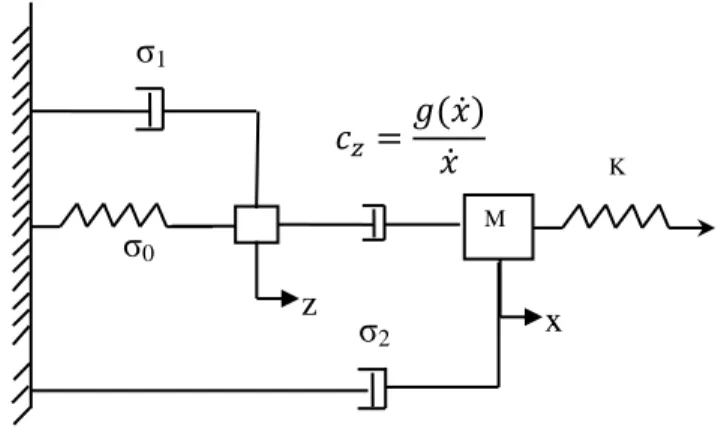
A hybrid spring-damper rate dependent friction model was developed to precisely simulate the friction process from zero velocity to the gross slip state. This was achieved by considering various physical phenomena during the friction process including the Stribeck effect, varying break-away force, bristle elastic, plastic and partial-slipping behaviors. The slipping time in the velocity-limited friction model was compared to the LuGre friction model. The inability of the velocity limited friction model to detect the sticking region was explained by the dependency of a limiting velocity criterion on the varying break-away force and the Stribeck effect. This confirmed the importance of having an adaptive limiting velocity for the velocity limited friction model. In addition, the stress distribution within the contact region was studied in detail to demarcate different regions within a contact area during the friction process. This analysis attributed a physical meaning to each component of the new hybrid friction model. The ability of the hybrid model to accurately reproduce stick-slip behavior was examined using the Ozaki and Hashiguchi friction model and the Baumberger et al. experimental tests. The result showed better estimation of the stick-slip behavior, both qualitatively and quantitatively, using the new hybrid friction model. In addition, the ability of the hybrid model, to reproduce pre-sliding displacements, was also examined using the Lim and Chen friction model and the experimental stability phase diagram, developed by Baumberger et al. The hybrid friction model reproduced the experimental phase diagram with qualitatively good agreement contrary to the Lim and Chen friction model. However, the magnitude of the stability velocity, in the hybrid model, had some
differences with the experimental result. This is mostly associated with the magnitude of the Stribeck velocity and damping coefficients in the hybrid friction model.
In the second part of the research, a series of tube-support experimental tests was performed to measure the related impact forces and mid-span displacements for various excitation amplitudes and gap sizes. The experimental program results were used as a reference database to carefully examine the impact model during tube-support interaction. The Euler-Bernoulli beam theory and modal superposition technique were also used to perform tube-support interaction dynamics computation. The structural damping measurements showed a varying magnitude depending on tube mid-span displacement. In addition, the effects of elastic and inelastic impact forces on the tube response were studied using the experimental results and numerical simulation comparisons. This study provided important insight into the elastic nonlinear force-displacement relationship during tube-support interaction. The estimation of the optimal parameter m, associated with this relationship, significantly reduced the difference between the experimental test results and the numerical simulations. In addition, an experimental program was undertaken considering the tube initial displacement as the origin of the excitation. This enabled a careful study of the tube displacement in a dissipative motion. The experimental tests and numerical simulation comparisons indicated the minor effect of the impact damping on the tube response, using the Hunt and Crossley model. The difference in the mid-span displacements was explained by increased energy dissipation through structural damping. This was modeled using a coefficient which represents a change in the structural damping from the onset of tube-support contact. The estimation of this coefficient indicated an increasing trend of the coefficient with increasing tube-support gap.
TABLE OF CONTENTS
ACKNOWLEDGMENTS ... III RÉSUMÉ ... IV ABSTRACT ... VI TABLE OF CONTENTS ... VIII LIST OF TABLES ... XI LIST OF FIGURES ...XII LIST OF SYMBOLS ... XV
INTRODUCTION ... 1
CHAPTER 1 LITERATURE REVIEW AND RESEARCH ORGANIZATION ... 4
Review of Previous Studies ... 4
1.1 1.1.1 Tube-support wear mechanisms ... 5
1.1.2 Tube-support interaction ... 6
1.1.3 Non-linear dynamic computations ... 10
1.1.4 Impact models ... 11
1.1.5 Friction models ... 12
1.1.5.1 Tube-support friction models ... 13
1.1.5.2 Rate-dependent friction models ... 14
1.1.5.3 Tangential stress distribution within contact region ... 16
Research Questions ... 18 1.2 Objectives ... 20 1.3 Thesis Organization ... 21 1.4 CHAPTER 2 NUMERICAL ANALYSIS OF FRETTING-WEAR WITH A HYBRID ELASTO-PLASTIC FRICTION MODEL ... 22
Introduction ... 23 2.1
Friction Models ... 24
2.2 2.2.1 Velocity-limited friction model (VLFM) (Tan and Rogers, 1996) ... 25
2.2.2 Force balanced friction model (FBFM) (Karnopp, 1985) ... 25
2.2.3 Spring damper friction model (SDFM) (Hassan and Rogers, 2005)... 26
Rate Dependent Friction Models ... 26
2.3 2.3.1 Ozaki and Hashiguchi friction model (Ozaki and Hashiguchi, 2010) ... 26
2.3.2 Lim and Chen friction model (Lim and Chen, 1998) ... 27
2.3.3 LuGre friction model (Astrom and Canudas de Wit, 2008) ... 28
Comparison of the LuGre and VLFM Models ... 29
2.4 Equivalent Spring-Damper Friction Model ... 34
2.5 Stress Distribution within the Contact Area ... 36
2.6 New Hybrid Spring-Damper Friction Model ... 40
2.7 2.7.1 Model formulation ... 41
2.7.2 Verification of model capabilities ... 43
Model Verification ... 46 2.8 Conclusions ... 50 2.9 References ... 51 2.10 CHAPTER 3 EXPERIMENTAL INVESTIGATION OF TUBE-SUPPORT NORMAL INTERACTION WITH A NONLINEAR IMPACT MODEL ... 55
Introduction ... 56
3.1 Experimental Rig and Measured Variables ... 60
3.2 3.2.1 Experimental test rig and instrumentation ... 60
3.2.2 Experimental procedure ... 63
3.2.3 Measured variable ... 64
Dynamic Computation of Tube-Support Interaction ... 65
3.3 3.3.1 Euler-Bernoulli beam modeling ... 65
Tube-Support Impact Model ... 66 3.4
3.4.1 Contact detection algorithm ... 67
3.4.2 Tube-support elastic interaction ... 67
3.4.3 Tube-Support inelastic interaction ... 69
3.4.4 Tube-support spring-damper impact model ... 69
Experimental Results and Numerical Simulation Comparisons ... 70
3.5 3.5.1 Tube forced vibration comparison ... 70
3.5.2 Tube-support interaction with a sinusoidal excitation ... 71
3.5.3 Tube-support interaction with initial displacements ... 82
3.5.3.1 Impact damping ... 83 3.5.3.2 Structural damping ... 85 Conclusions ... 89 3.6 References ... 91 3.7 CHAPTER 4 GENERAL DISCUSSION ... 95
Review of Objectives ... 95
4.1 Further Discussion ... 96
4.2 4.2.1 Friction model discussion ... 96
4.2.2 Impact model discussion ... 100
Main Contributions ... 102
4.3 Recommendations for Future Work ... 103
4.4 CONCLUSIONS ... 104
REFERENCES ... 106
LIST OF TABLES
Table 2.1 The LuGre model parameters (Canudas de Wit et al., 1995) ... 29
Table 2.2 Mass-spring model parameters. ... 47
Table 2.3 New friction model parameters. ... 47
Table 2.4 New friction model parameters. ... 47
Table 3.1 Experimental test parameters. ... 61
Table 3.2 Excitation force amplitude for each gap size. ... 63
Table 3.3 Initial displacements of the tube mid-span. ... 64
Table 3.4 Simulation model parameters. ... 73
Table 3.5 Tube-support simulation parameters ... 74
Table 3.6 Tube-support experimental parameters. ... 76
LIST OF FIGURES
Figure 2-1 The Stribeck velocity effect on switching from stick state to slip states. ... 29
Figure 2-2 Mass-spring system. ... 30
Figure 2-3 Break-away forces comparison for the Velocity Limited Friction Model and the LuGre model with different pulling velocity (a) vp = 0.1 (m/s), (b) vp = 0.2(m/s), (c) vp = 0.4 (m/s). ... 31
Figure 2-4 Slipping time for the LuGre Model and Velocity-Limited Friction model (a) The LuGre slipping time (b) The VLFM slipping time (c) Difference between the LuGre and VLFM. ... 32
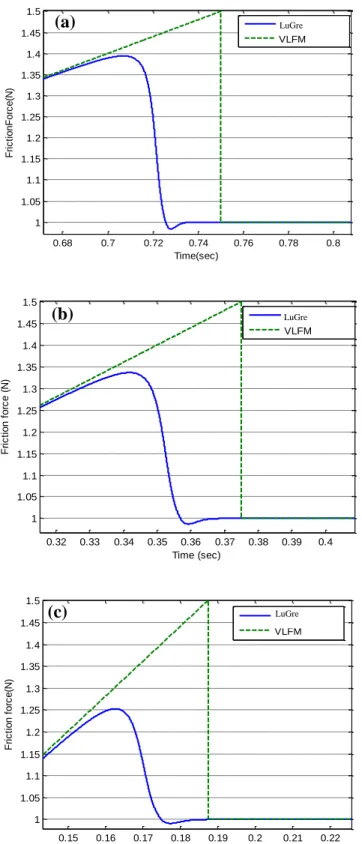
Figure 2-5 Slipping time comparison the VLFM and LuGre (1) chirp [1,5] (2) chirp [1,10] (3) chirp [1,20] (4) chirp [1,30]. ... 33
Figure 2-6 Slipping time percentage versus logarithmic average bristle deflection. ... 34
Figure 2-7 Spring-damper model equivalent to the Lugre Model. ... 35
Figure 2-8 Slipping time comparison between the LuGre and Revised SDFM for different logarithmic rate of average bristle deflection. ... 35
Figure 2-9 Cattaneo-Mindlin tangential stress distribution (Johnson, 1955). ... 36
Figure 2-10 Stick and slip point in contact region (Johnson, 1985). ... 37
Figure 2-11 Two flat surfaces in contact. ... 39
Figure 2-12 Tangential stress distribution for a flat punch (Johnson, 1985). ... 39
Figure 2-13 Displacement field in the contact area and hybrid spring-damper model. ... 41
Figure 2-14 New hybrid spring-damper friction model. ... 42
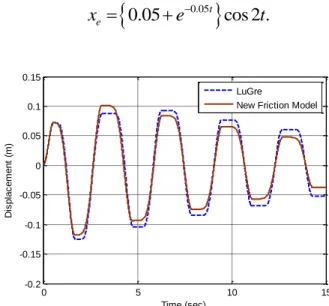
Figure 2-15 Displacement comparison between the LuGre and the new friction models using Equation (2-28) as the excitation. ... 44
Figure 2-16 Elastic, plastic, partial slipping displacement. ... 44
Figure 2-17 Displacement comparison the LuGre and new friction models. ... 45
Figure 2-19 New hybrid friction model, Ozaki and Hashiguchi friction model (Ozaki and
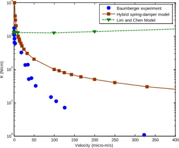
Hashiguchi, 2010) and Baumberger et al. experiment (Baumberger et al., 1994) comparisons. ... 48 Figure 2-20 K-V dynamic phase diagram for the stick-slip stability for the Baumberger et al. experimental tests (Baumberger et al., 1994) , Lim and Chen model (Lim and Chen, 1998) and Hybrid spring-damper model. ... 49 Figure 3-1 Tube-support experimental rig. ... 60 Figure 3-2 Experimental rig including tube, support, fixture and electromagnetic exciter. ... 62 Figure 3-3 Experimental rig with measuring instruments including force transducers and laser displacement sensors. ... 62 Figure 3-4 Tube-support impact model. ... 69 Figure 3-5 Experimental measurement of the tube structural damping. ... 70 Figure 3-6 Tube mid-span displacement comparisons experiments and numerical simulations. .. 71 Figure 3-7 Impact forces comparison between simulations and experiments ... 72 Figure 3-8 Impact force time history for the experimental test and numerical simulation using .. 75 Figure 3-9 Close-up of a tube-support multiple impact during one interaction ... 76 Figure 3-10 Experimental test and numerical simulation of the tube mid-span motion in the horizontal plane normal to the support. ... 77 Figure 3-11 Impact force comparisons experiments and simulations for m=∞ and m=1.67. ... 77 Figure 3-12 Mid-span displacements and impact forces for the experimental tests and numerical simulations. ... 78 Figure 3-13 The differences between the experimental measurements and numerical simulations: (a) impact forces (b) mid-span displacements. ... 80 Figure 3-14 Impact force and mid-span displacement between the experimental measurements and numerical simulations (a) 0.25 mm gap size (b) 0.75 mm gap size. ... 81 Figure 3-15 Tube-support response comparison between simulation and experiment, beginning with the first tube-support interaction. ... 83
Figure 3-16 Tube-support response comparison between simulation and experiment with β=0.3
and β=0.08. ... 84
Figure 3-17 Tube-support response comparison between simulation and experiment with parameter q=0.5 and 1.5. ... 85
Figure 3-18 Experimental and numerical simulation of tube-support interaction for ε=1 and ε=20. ... 87
Figure 3-19 Experiment and simulation differences versus parameter ε for the initial displacements d1-d4 and gap size 0 mm. ... 87
Figure 3-20 Experiment and simulation differences versus parameter ε for initial displacements d1-d4 and gap size 0.75 mm... 88
Figure 3-21 Ranges of the optimum parameter ε for different gap sizes. ... 89
Figure 4-1 Displacement field in the contact area and hybrid spring-damper model. ... 98
Figure 4-2 New hybrid spring-damper friction model. ... 98
Figure 4-3 K-V dynamic phase diagram for the stick-slip stability for the Baumberger experimental test (Baumberger et al., 1994) , Lim and Chen model (Lim and Chen, 1998) and Hybrid spring-damper model. ... 99
Figure 4-4 Mid-span displacements and impact forces for the experimental tests and numerical simulations. ... 101
LIST OF SYMBOLS
A Tube cross-section area[m2]
a Contact radius[m]
C Damping coefficient[Ns/m]
cp Plastic damping coefficient[Ns/m] cs Slipping damping coefficient[Ns/m] cz Stribeck damping coefficient[Ns/m] D0 Average presliding displacement[m]
Di Inner diameter[m]
Do Outer diameter[m]
E Young modulus[Pa]
EI Bending stiffness[N.m2]
f Frequency[Hz]
Fd Impact damping force[N]
Fe Excitation force[N]
Fex Excitation force x-direction[N] Fez Excitation force z-direction[N]
Ff Friction force[N]
Fs Static friction force[N] Fc Coulomb friction force[N]
Fn Normal force[N]
Ft Tangential force[N]
FTy Fretting yield force[N]
G Shear modulus[Pa]
K Stiffness coefficient[N/m]
Ku Internal resistance force[N]
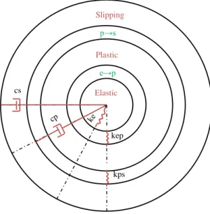
ke Tangential elastic stiffness[N/m] kep Tangential elasto-plastic stiffness[N/m] kp Work hardening coefficient[N/m]
kps Tangential plastic-slipping stiffness[N/m] ks Support stiffness[N/m]
L Tube length[m]
Ls Support length[m]
M Mass[Kg]
qnz,qnx Modal responses
t Tube thickness[m], Time[s]
T* Amplitude of tangential oscillatory force[N]
v Poisson ratio
V0 Limiting velocity[m/s]
Vt Tangential velocity[m/s]
vs Stribeck velocity[m/s]
u0 Zero velocity tangential displacement[m] uc Current velocity tangential displacement[m]
uz Normal indentation[m] w Contact width[m] ze Elastic displacement[m] zp Plastic displacement[m] zs Partial-slipping displacement[m] Greek µ Friction Coefficient
µk Kinetic friction coefficient µs Static friction coefficient
ξ Structural damping ratio
ξs Structural damping ratio during contact
ϕ State variable[m]
φn(x) Mode shapes
η Viscous damping[Ns/m]
ζ0 Friction stiffness coefficient[N/m]
ζ1 Friction presliding damping coefficient[Ns/m] ζ2 Friction viscous damping coefficient[Ns/m]
Δ1 Tube-support clearance[m]
ΔE Friction energy dissipation[N.m] δ Total presliding displacement[m]
ρ Density[kg/m3] ωn Natural frequency[Hz] Subscripts e Elastic p Plastic ps Partial-slipping r Radial displacement s Support t Tangential z Normal direction x Tangential direction Abbreviation
EPRI Electric power research institute FBFM Force-balanced friction model VLFM Velocity-limited friction model
VITRAN Vibration transient analysis–nonlinear (Code)
r.m.s Root mean square
INTRODUCTION
Fretting-wear is a challenging problem which is frequently encountered in different mechanical systems including steam generators. A steam generator is mainly comprised of a tube bundle which transfers heat from the primary loop coolant, within the tubes, to secondary loop water, external to the tubes. The tubes are then subjected to both parallel and cross-flow in different phases, including liquid, gas or two phase. This causes flow-induced forces on the tubes, including fluid elastic and turbulence forces. On the other hand, the concerns associated with thermal expansion, installation and manufacturing may lead to development of a more flexible tube-support structure. Tube-support interaction is therefore unavoidable as a result of flow-induced vibration. The long term interaction may cause tube fretting-wear and subsequently tube rupture. This undesired fretting-wear may affect the safety and performance of a nuclear power station. Data provided by Electric Power Research Institute (EPRI) suggested that, in 1994, 49 percent of all pressurized water reactor steam generators were overhauled as a result of the above mentioned tube-support fretting-wear (Dierecks et al., 1996). The report suggested an average cost of 100-200 million dollars per plant for steam generator tube replacements.
The importance of the tube-support fretting-wear problems has raised a lot of interest among researchers. Many studies have been conducted to investigate and estimate flow-induced forces (Pettigrew et al., 1978; Lever and Weaver, 1982; Pettigrew and Taylor, 1994; Pettigrew et al., 1998; Weaver et al., 2000; Païdoussis et al., 2010). On the other hand, many authors have studied tube-support interaction in terms of impact and friction (Rogers and Pick, 1977; Sauve and Teper, 1987; Fisher, 1989; Chen, 1991; Fisher et al., 1992; Tan and Rogers, 1996; Hassan et al., 2002). The ultimate goal of these studies is to quantify fretting-wear during tube-support interaction. Work-rate is a factor which quantifies wear-rate. This factor is strongly dependent upon sliding distance and normal contact force. It is therefore important to have precise friction and impact models to carefully quantify tube-support fretting-wear.
The velocity-limited friction model (Rogers and Pick, 1977), force-balanced friction model (Karnopp, 1985) and spring-damper friction model (Antunes et al., 1990) are the three main friction models which have been widely used in the tube-support interaction simulation. The main differences between the friction models are the criteria employed to detect the stick-slip
regions and estimation of the sticking friction force. In the friction models above, the criteria to detect the stick-slip regions are not physics based and often lead to errors in the estimation of the sliding distance. Furthermore, in these models, the transition behavior from the stick to slip phases has not been considered. The study of the motion from zero velocity to the gross sliding phase is crucial to obtaining a physics based criterion for detection of the stick-slip regions. The LuGre Friction model (Canudas de Wit et al., 1995), the Ozaki and Hashiguchi friction model (Ozaki and Hashiguchi, 2010) and the Lim and Chen friction model (Lim and Chen, 1998) are three examples of rate dependent friction models. The friction models consider the transition behavior from the stick to slip phases. Furthermore, the models also take into account the nonlinearity in the vicinity of zero velocity. The precision of the friction models makes them good enough for use in robotic and control systems. However, no attempt has been made to correlate the friction models to the tangential stress distribution.
The study of the tangential stress distribution within the contact region is a crucial step in investigating the bristle behavior during the friction process from the absolute zero velocity to the gross slip state. Cattaneo-Mindlin (Cattaneo, 1938; Mindlin, 1949), Mindlin and Deresiewicz (1953) and Odfalk and Vingsbo (1992) endeavored to correlate the physical phenomena in the friction process to the tangential stress distribution within the contact region. As the result of the studies, the friction process was divided into the three stages of elastic, plastic and partial-slipping regions. From the fretting-wear point of view, the different stages may result in different wear coefficients. Therefore, developing a rate-dependent friction model which can demarcate the different regions of elastic, plastic and partial-slipping is expected to be particularly beneficial.
The estimation of the impact force is a crucial step in the tube-support interaction analysis due to the subsequent effect on the friction force, stick-slip regime and work-rate calculation. Some efforts have been dedicated to modeling the impact force (Axisa et al., 1984; Sauve and Teper, 1987; Yetisir and Fisher 1997). However, the nonlinearity involved in the force-indentation relation has not been studied. Furthermore, the study of the source of energy dissipation during the normal interaction should be a beneficial step. The evaluation of the incorporated impact model in the dynamic modeling of the tube-support interaction, for a real heat exchanger tube, is a challenging step due to the involvement of different factors such as the
fluid-induced forces, multiple supports, support types and friction force. Therefore, for the impact model validation, the replacement of the complicated factors by a simplified laboratory experimental rig may be valuable.
The motivation of the present work may be summarized as follows: fretting wear of nuclear steam-generator tubes remains an important problem in industry both for safety and cost reasons. While significant work has been done too address this problem, and in particular to model tube-support interaction for wear estimation, important questions and challenges remain.
To better estimate the wear work-rate more accurate models for the friction and impact phenomena are needed. In order to develop this next generation of models previously unmodelled details of the tube-support interaction need to be taken into account. This includes consideration of the tangential stress distribution within the contact region as well as correctly modelling the various states or stages of the friction process (including sticking, partial slip and gross slip). In addition the nonlinear impact process needs improved modelling. Finally, the new, inherently more complex models must be verified by incorporation into full multimode tube models. Dynamic analyses then need to be carried out and to the extent possible, comparison with experimental tests done.
CHAPTER 1
LITERATURE REVIEW AND RESEARCH ORGANIZATION
In this section a detailed review of previous work on tube-support interaction is presented. The literature review is followed by a summary of key research questions in Section 1.2. The objectives of the proposed research are presented in detail Section 1.3. The thesis organization is outlined in Section 1.4.
Review of Previous Studies
1.1
This section will review the state of the art on tube-support wear mechanisms, dynamic computation, impact and friction models. In the heat exchanger and steam generator tube bundles, contacts between the tube and support are unavoidable due to the flow-induced vibration. This interaction causes fretting-wear which may consequently lead to tube failure (Fisher et al., 1992; Hassan et al., 2002). Chen (1991) divided the causes of tube failure in heat exchangers into four different phenomena: interaction and wear between the tubes, interaction and wear between the tube and support, joint failure at the tube to tube-sheet interface and tube fatigue. The causes of the excessive vibration and subsequently fretting-wear are flow-induced forces. Flow-induced vibration mechanisms can be classified as fluid-elastic instability, vorticity shedding, turbulence buffeting and acoustic excitation (Pettigrew et al., 1978; Pettigrew et al., 1998). These flow-induced mechanisms can lead to significant tube vibration and interaction with supports. The interaction may then cause tube fretting. The fretting may be classified as fatigue-fretting, fretting-wear and fretting-corrosion (Magaziner et al., 2004). Several authors have studied different aspects of the tube and support dynamics, to come up with better fretting-wear estimation. It is an intricate process to develop a precise contact model due to the difficulties in simulating the fluid forces and unknown contact interface conditions (Popp, 2005). However, several codes have already been developed to simulate the tube-support interaction including VIBIC (Rogers and Pick, 1977), H3DMAP (Sauve and Teper, 1987), GERBOISE (Axisa et al., 1986), INDAP (Hassan, 2000; Hassan et al., 2002; Hassan et al., 2003), VITRAN (Rubiolo, 2006) and FIVDYNA (Toorani et al., 2009).
To have a better estimate of the tube-support interaction behavior during flow-induced vibration, a precise model is needed for each component of the tube-support system including: the fluid excitation forces, tube-support dynamics, tube-support impact, tube-support friction and effects of various system parameters (Chen, 1991).
1.1.1 Tube-support wear mechanisms
An oscillatory relative surface interaction between two objects may result in fretting-wear. Accurate wear-rate estimation is important for the prediction of the life time of the engaged components and their replacement time (Gessesse, 2000). During the interaction, different wear mechanisms may be activated. The type of mechanisms is dependent upon the relative motion of the components, interaction forces magnitude, geometry of the contact, type of materials and operating conditions of the system (Ko, 1986). Due to the flow excitation mechanisms in the steam generator tube bundle, contacts between the tubes and supports occur. These contacts may be categorized as normal, tangential or oblique impacts (Hofmann et al., 1992). The dominant wear mechanism for each type of interaction is different. Therefore, the incident impact angle, which quantifies the type of interaction, plays an important role in the tube-support dynamic computation. The angle may be defined by different system parameters such as: the tube pre-load conditions, flow excitation mechanisms and tube-support interaction forces (Haslinger and Steininger, 1995). To better understand the interaction, it is important to study the interaction forces and subsequently the mechanisms which may be involved in material removal during the wear process.
Different wear processes may be involved during the tube-support interaction such as adhesive, abrasive, delamination, fatigue and corrosion wear (Gessesse, 2000). However, based upon the real working conditions of the heat exchangers, the most dominant wear mechanism in the tube-support interaction may be a combination of the abrasive, delamination and fatigue wear mechanisns (Suh, 1973; Lee et al., 2001; Gessesse and Attia, 2004). Based upon the delamination theory of wear, proposed by Suh (Suh, 1973), the causes of wear are the dislocations at the contact surface, sub-surface crack propagation and void formation (Suh, 1973), (Fleming and Suh, 1977). In an extension of the Suh study (Suh, 1973), different authors have tried to evaluate the wear process both experimentally and theoretically. Argon and Im (1975) proposed a crack propagation criterion to evaluate crack initiation and plastic region formation (Jahanmir and Suh,
1977). The experimental studies conducted by Suh (1973), Gauland and Duquette (1980) and Waterhouse (1981) indicated that cracks may be propagated parallel to the contact surface in the material sub-layer. Furthermore, it was reported that the propagation may take place in an approximate depth of 0.8 to 1.8 times of the micro-contact radius from the contact surface and that due to the numerous cyclic loadings, the crack may grow until reaching the critical length of 1 to 1.4 times of the micro-contact radius. After the crack reaches the critical length, it may progressively change its direction toward the contact interface. The process may consequently form wear debris (Suh, 1973; Fleming and Suh, 1977).
1.1.2 Tube-support interaction
Since the most important causes of tube wear are friction and impact, many authors have tried to model and simulate these phenomena theoretically and experimentally. Different experimental tests have been carried out to establish the relations between the tube-support wear rate and different experimental parameters such as tube-support clearance, support type, friction coefficient and loading conditions.
Axisa et al. (1984) conducted experimental tests to measure the impact force and mid-span displacement during the tube-support interaction for a tube with multiple supports. In the experimental rig, the supports had quatrefoil hole shapes. The tests were conducted for different gap sizes and excitation forces. The results indicated a reasonable trend agreement between the impact forces in the experimental tests and numerical simulations. However, the mid-span displacements indicated significant differences particularly with increasing tube-support gap size.
Haslinger et al. (1990) characterized the squeeze film effect during tube-support interaction. The study investigated the effect of varying gap sizes on the fluid squeeze film phenomenon. The authors also obtained semi-empirical expressions for the effect. Subsequently, Haslinger et al. (1995) conducted experimental tests to estimate the coefficient of friction during tube-support interaction. The results justified the usage of the same friction coefficient for the tube-support oblique impact and gross sliding. Additionally, these results indicated that the friction coefficient is independent of the normal force.
Chen et al. (1985) and Chen (1991) conducted experimental tests to understand the effectiveness of the support. The authors defined two different support modes support active and
support inactive modes. The support active mode may be activated due to relatively small clearance which causes the support to behave effectively. On the other hand, for relative large gaps, the support may not perform effectively which may activate the support inactive mode. The study indicated that during the tube-support interaction, the support mode was usually a combination of the two different modes. Furthermore, the study showed that the tube response may be different depending upon the activation of different modes. The phenomena were then explained based upon changes in the tube-support natural frequency for the different modes. In addition, the Moretti and Lowery (1973) study emphasized the change in the natural frequency depending on the support mode, excitation amplitude and clearance.
Yetisir and Fisher (1997) studied the interaction between fuel channel and fuel elements subjected to a turbulence-induced force caused by an axial flow. For the numerical simulation, the VIBIC code (Rogers and Pick, 1977), based upon the modal superposition method, was used. In the study, different parameters were investigated such as contact stiffness, friction coefficient, damping, support length and gap sizes.
Attia and Magel (1999) carried out experimental tests to investigate the long term fretting-wear behavior in straight and U-bend tubes. The authors tried to study the effect of the tube-support clearance on the wear-rate and subsequently find a relationship between the wear-rate and work-rate. The results indicated that the work-rate decreased with increasing gap-size. However, the trend had a non-monotonic behavior which suggested a self-limiting property for fretting-wear during tube-support interaction.
Lee et al. (2001) conducted experimental tests to evaluate the wear behavior during the tube-support interaction in steam generators. In the experimental tests the tube materials were chosen as Inconel 600MA and 690TT. The support materials were 405 and 409 ferritic stainless steels. The normal load and sliding amplitude were gradually increased and the worn contact interface was carefully observed with the help of a scanning electron microscope. Moreover, the wear coefficient was determined and the effect of the material compositions and surface hardening were investigated. The results indicated that different wear mechanisms may be involved during the tube-support interaction. These mechanisms may strongly depend upon the magnitude of the chromium content which may define the level of the work hardening during the interaction. The morphology investigation of the worn surface indicated that fine wear particles
were formed on the worn surface even after ultrasonic cleaning. The particles were formed due to the high shear plastic deformation on the contact interface and crack propagation in the material sub-layer. These particles became even finer due to the continuous wear process and normal compressive pressure. It was therefore suggested that a wear protective layer may be formed. It is pertinent to note that such a layer behaves differently for Inconel 600MA compared to Inconel 690TT. For Inconel 600MA, the protective layer did not strongly stick to the contact interface. Therefore, it was worn away during the abrasive wear process. In contrast for Inconel 690TT, the protective layer strongly adhered to the worn surface due to the high chromium content. Thus, the wear coefficient may be lower for Inconel 690TT compared to Inconel 600MA.
Attia et al. (2007) elaborated the fretting-wear mechanisms during the tube-support interaction. To achieve this goal, the authors proposed a physical parameter based upon the worn surface morphology and fracture mechanics mechanisms. The new paramater corrolates the energy dissipation to the wear loss by demarcating the different types of the tube orbital motions.
Nowlan et al. (2009) studied the tube-support interaction via a series of sweep test excitations in the direction parallel to a support in contact with a two-span tube. In this study the tube natural frequency was carefully measured. Furthermore, the contact forces were measured for different preload, gap sizes and support orientation. It was concluded that the natural frequency was not changed by the interaction. On the other hand, the stick-slip behavior and normal tube-support interaction transferred energy to the higher tube modes. The results also underlined the sensitivity of the tube response to the tube-support clearance.
Many authors have developed models to simulate the tube response using numerical techniques. Rogers and Pick (1977) used a finite element method to study the tube-support interaction. The study considered the effect of damping, tube stiffness and gap size on the interaction forces. Fisher et al. (1989) validated the work-rate estimation in the VIBIC code against experimental tests. Tan and Rogers (1996) attempted an evaluation of the effect of the force-balanced friction model on the tube-support wear-rate estimation. In the study, the friction model was incorporated into the VIBIC code for different types of supports including circular, semi-circular and scallop-bar types. The work-rates for different gap sizes were also compared against the experimental tests conducted by Yetisir and Fisher (1997).
Hassan et al. (2002) studied the tube-support interaction for a tube subjected to turbulence induced forces. In the study, a nonlinear dynamic analysis based upon a finite element method was used for the simulation. The normal impact model was chosen based upon the Sauve and Teper impact model (Sauve and Teper, 1987). The velocity-limited friction model was incorporated in the numerical simulation and the turbulence excitation modeling based upon the Oengoren and Ziada study (Oengoren and Ziada, 1995) was used. There were also comparisons made between the impact forces among the three different dynamic computation codes including H3DMAP (Sauve and Teper, 1987), INDAP (Hassan, 2000; Hassan et al., 2002; Hassan et al., 2003) and VIBIC (Rogers and Pick, 1977). The results indicated a significant increase in the work-rate estimation due to support offset. The complex behavior of the tube response was investigated by introducing a dimensionless clearance as the ratio of radial clearance to r.m.s support response.
Hassan et al. (2005) simulated the tube-support interaction by considering a new impact model. Due to the difficulties in accurately estimating the contact area and contact pressure distribution, the contact model is commonly simplified to a point contact in which the support is assumed to be a knife edge. However, in Hassan et al.‟s study, the real contact region was modeled as a segmental contact. Furthermore, the point and segmental contact stiffness was modeled with a single spring and distributed contact stiffness, respectively. The model indicated that the nature of the tube-support interaction is a combination of the edge and segmental contacts. Furthermore, the study specified a higher possibility of encountering a segmental contact by decreasing the tube-support gap sizes. Different factors such as the support preload, clearance and tube alignment may affect the type of contact during the interaction. For instance when the clearance is small in the presence of a large preload, the interaction may mostly occur in the sliding mode and the appropriate model is the segmental contact. On the contrary, for a large clearance with a small preload, intermittent contacts may mostly occur. In this case the appropriate model is the point contact.
Hassan and Rogers (2005) studied the impact and friction forces during tube-support interaction. In the study, different friction models including the velocity-limited friction model, force-balanced friction model and spring damper friction model were incorporated in the numerical simulations. Furthermore, the work-rate was calculated for the different friction
models and tube-support clearances. The results indicated a good agreement between experimental results and numerical simulations for the large preloads in contrast to the case of small preloads.
1.1.3 Non-linear dynamic computations
Sauvé and Teper (1987) developed an implicit numerical integration scheme for tube-support vibro-impact interaction based upon a finite element method. The program has the flexibility of changing the time-step to minimize errors and obtain the optimum result. Furthermore, the lumped mass approach and Rayleigh proportional model were used to form the mass and damping matrices. The Newmark scheme (Bathe, 1982) was used for integrating the nonlinear equations. As the result, a dynamic computation code, called H3DMAP, was developed to simulate the flow-induced tube-support interaction.
Hassan et al. (2002) developed a computer code called INDAP to simulate the tube-support interaction. The authors used a standard finite element procedure to solve the tube‟s equation of motion. Using the FEM procedure is extremely costly in terms of time, due to the incipient contact search algorithm. Therefore, the authors adapted a pseudo-force approach developed by Subbaraj and Dokainish (1989). The method simplified the nonlinearity of the system by introducing an external force into the equation of motion.
Another code, developed at AECL, is VIBIC (vibration of beams with intermittent contact) (Fisher et al., 2001). VIBIC is designed for the structural dynamic analysis of tube-support interaction. In the program, the tube dynamic response is determined by the modal superposition technique. Similarly to the Subbaraj and Dokainish (1989) method, the tube-support nonlinearity due to the clearance was modeled by introducing an equivalent external force to the system. The equations of motion are numerically solved using the fourth-order Runge-Kutta algorithm.
VITRAN (vibration transient analysis–nonlinear) (Rubiolo, 2006) is another computer code used to simulate the dynamic response of fuel rods. This nonlinear dynamic analysis code was developed based upon the Euler-Bernoulli beam theory similarly to the study by Antunes et al. (1990). In the governing equations, the rotational inertia and shear deformation are neglected. Further, the unconstrained modal superposition is used to determine the dynamic behavior of the
system. Instead of using the constrained mode shapes the use of the unconstrained mode shapes was explained by the relatively small difference in the results and time consumption cost of using the constrained mode shapes. The numerical analysis by Davies and Rogers (1979) also suggested the admissibility of using unconstrained mode shapes for systems with very low structural damping coefficient.
1.1.4 Impact models
Goyal et al. (1994) divided the impact model into two parts: the first being the detection of the contact between the two bodies and the second the force calculation due to the interaction. An accurate estimation of the normal contact force is an essential part of the interaction modeling due to the subsequent effect on the friction force and stick-slip regime estimation. One of the theories developed to analyze the contact behavior between two bodies is the Hertz‟s contact theory (Johnson, 1985). In Hertz‟s theory, the contact region is assumed to be continuous and relatively small compared to the bodies‟ dimensions (Johnson, 1985). The bodies involved during the interaction are also considered as completely elastic (Johnson, 1985). The contact surfaces are assumed to be frictionless surfaces (Johnson, 1985) and the only force which may be transferred during the interaction is the normal force. Deformation boundary forces are not considered in the model (Johnson, 1985). To take into account the boundary deformation forces, Thornton and Randall (1988) proposed an impact model which considered neighboring deformation based upon a feedback finite element algorithm (Goldsmith, 1960; Johnson, 1985). However, in the case of the tube-support interaction, the thin circular cross-section may affect the contact stiffness by the ovalization phenomenon. Therefore, Morley (1960) studied the ovalization effect for a force couple acting on a thin cylinder. The study assumed that the acting forces are far from the cylinder edges. This enabled the researchers to arrive at an estimate of the stiffness coefficient for the ovalization effect.
During interaction between two bodies, three mechanisms of energy dissipation may be involved including: shear, normal damping and structural damping dissipations. These sources of energy dissipation may be in the form of the elastic waves, viscoelasticity and plastic deformation (Goyal et al., 1994; Stevens and Hrenya, 2005). The coefficient of restitution is the quantity characterizing the energy dissipation during interaction between compact bodies. Different definitions for the coefficient of restitution have been proposed including: the Newtonian
hypothesis based upon the velocity ratio, the Poisson‟s hypothesis based upon the impulse ratio for the two different impact phases; loading and unloading and the Stronge hypothesis based upon absorbed energy during the interaction (Goyal et al., 1994; Stronge, 2000). There are some difficulties associated with the estimation of the coefficient of restitution. For instance there is no perfect rough surface to prevent sliding and so some of the energy may be dissipated in the form of friction (Goldsmith, 1960). It is also pertinent to point out that due to plastic deformation, torsion and other impact boundary conditions, it is essential to evaluate a precise coefficient of restitution through a semi-empirical formula based upon material properties, impact velocity and impact interface geometry (Goldsmith, 1960).
Hunt and Crossley (1975) developed a model for the normal interaction between two bodies considering energy dissipation. The bodies were assumed to be compact solid bodies and the effect of reflected elastic shock wave was not considered in the model. The three main factors of the model are elastic impact force, coefficient of restitution and impact velocity which may affect the normal damping force estimation.
For a continuous system interaction such as the tube-support system, defining a coefficient of restitution is problematic. The Thomson et al. (1994) study on continuous system interaction indicated that the higher modes are excited. The authors suggested that the measured coefficient of restitution may underestimate the energy dissipation (Wagg and Bishop, 2000). Another study by de Weger et al. (1996) laid emphasis on the higher mode energy transfer (dissipation) during a continuous system interaction. However, the nature of chaotic multi-impact behavior of the tube-support interaction in a short interaction duration introduces uncertainties on the experimental measurements (Werner and Robert, 2008). Different authors have theoretically analyzed the multi-impact behavior and the coefficient of restitution value in continuous systems (Shaw, 1985; Stoianovici and Hurmuzlu, 1996; Bao et al., 2004; Wagg, 2005; Wagg, 2007).
1.1.5 Friction models
Different friction models have been developed for the evaluation of friction induced stick-slip behavior. The incorporated friction model in the tube-support dynamic computation scheme is important particularly due to the nonlinear behavior of the friction force in the vicinity of zero sliding velocity. The main differences among different friction models are their approaches to the detection of the stick-slip regions, estimation of the friction force in the sticking phase and
transition modeling from the sticking to slip phases. In this section, the state of the art in the commonly used friction models in the tube-support interaction modeling is described. In addition the rate-dependent friction models and tangential stress distribution within the contact area are also reviewed.
1.1.5.1 Tube-support friction models
The velocity-limited friction model (VLFM) is one of the friction models which is widely used in tube-support dynamic simulation. In the model, a limiting velocity is defined to demarcate the stick-slip regions. The friction force in the sliding phase is determined similarly to the Coulomb friction model. On the other hand, the friction force in the sticking phase is proportional to the limiting velocity for sticking. The model was described by several authors such as Rogers and Pick (1977) and Tan and Rogers (1996).
Karnopp (1985) proposed a one-dimensional force-balanced friction model (FBFM) by demarcating the slip and sticking regions based upon defining a velocity window. The friction force during the sliding phase in the force-balanced friction model may be defined similarly to the Coulomb friction model. However, the friction force in the sticking region is calculated by balancing the net force to keep the velocity equal to zero in this region.
Antunes et al. (1990) proposed a spring-damper friction model (SDFM). The model was designed to precisely determine the sticking friction force and to take into account the nonlinearity in the vicinity of zero velocity. To achieve these goals, a parallel spring and damper system was implemented to estimate the sticking friction force. In the model, the stick and slip regions may be demarcated by the sign of the dot product of the instantaneous velocity in the current and previous time steps. Furthermore, the spring stiffness and damping coefficient were determined based upon the numerical stability of the model rather than physical quantities.
Tan and Rogers (1996) analyzed a two-dimensional system with two different friction models, including the spring-damper friction model based upon the Antunes et al. (1990) study and the force-balanced friction model based upon the Karnopp (1985) study. The results indicated a weakness of the velocity sign criterion used to detect the stick-slip regions for a two-dimensional dynamic analysis. Comparisons of the models indicated that using the
force-balanced friction model may lead to better numerical stability in the simulation response and more accurate detection of the stick-slip regions.
Tariku and Rogers (2001) improved the force-balanced and spring-damper friction models to have a better estimation of the stick-slip regions. The Karnopp force-balanced friction model (Karnopp, 1985) uses a velocity window to define the sticking region. The boundary condition may result in an error associated with a large time-step since the algorithm may not detect the small velocity window. Therefore, the force-balanced friction model was improved by considering two criteria to precisely detect the sticking regions including, the velocity sign criterion and maximum friction force limitation. The results indicated that the implementation of these criteria rather than using the velocity window may lead to a lower sticking velocity error. For the spring-damper friction model, the authors suggested using three criteria to confirm the occurrence of sticking including, the velocity sign change criterion, net external force limitation and spring-damper force limitation. As a result of the modification, the occurrence of a spike in the beginning of the sticking region was eliminated. The authors also analyzed the effect of different system parameters including the time-step, duration of simulation, initial conditions, spring stiffness and damping coefficient.
1.1.5.2 Rate-dependent friction models
The modeling of the transition from the sticking to slip phases is a challenging problem due to the dependency of the model on elastic, plastic and partial slipping behavior of the bristles within the contact region. Rabinowicz (1951) experimentally studied the transition between the static and dynamic phases. In the study, the transition was explained based upon the breakage of the metallic junctions in the contact interface. Therefore, the transition function may strongly depend upon the relative velocity of the interfaces. Many authors have worked on the development of a mathematical function to precisely reproduce the stick-slip transition (Wojewoda et al., 2008), the Stribeck effect (Stribeck, 1902). The Exponential distribution (Tustin, 1947), Gaussian distribution (Armstrong-Helouvry, 1991) and Laurentzian distribution (Hess and Soom, 1990) have been considered in the modeling.
Dahl (1968) developed a friction model based upon the stress-strain curve of the bonds formed within the contact interface. The author adopted the concept of metallic junctions formation and subsequent yielding and breaking of the junctions in the friction process. In the
model, the bristle deflection was simulated by introducing an internal state variable. The friction force was then proportional to the magnitude of the state variable.
The LuGre friction model, developed by Canudas de Wit et al. (1995), was an upgrade of the Dahl model considering the effect of varying break-away force, pre-sliding displacement, Stribeck effect and friction hysteretic behavior. The model was inspired by the idea of average bristle deflection. Therefore, the friction force in the model was decomposed into three terms depending upon the average bristle deflection, rate of change of the average bristle deflection and the relative velocity of the two interfaces. The Stribeck stick-slip transition function was incorporated in the LuGre model based upon the Gaussian function proposed by Armstrong and Helouvry (1991).
The presliding displacement in the LuGre friction model (Canudas de Wit et al., 1995) was considered to include the plasticity in the whole process of presliding. The assumption may cause an unbounded displacement when a small oscillatory force acts on the system. For this reason, Dupont et al. (2002) tried to eliminate this effect by demarcating the elastic and plastic presliding regions. However, the elastic to plastic demarcation criterion was a challenging step in the model.
Armstrong and Qunyi (2008) studied the presliding behavior in different friction models using internal state-variables. This work indicated that the presliding might be assumed to be elastic or plastic depending on the definition of the state-variable in the friction model. It emphasized the importance of choosing a proper friction model based upon the application and required sensitivity. Astrom and Canudas-de-Wit (2008) studied the LuGre friction stick-slip behavior by considering different system properties such as pre-sliding displacement, invariance and passivity.
Ozaki and Hashiguchi (2010) developed a friction model to study the intermittent stick-slip behavior in an unstable friction-induced phenomenon. In the model, the rate of change in the instantaneous friction coefficient is dependent on the coefficient of friction and plastic sliding velocity. The model also considered the friction coefficient softening effect during the transition from the sticking to slip phases and the hardening effect during the transition from the slip to stick phases.
Baumberger et al. (1994) experimentally studied the motion of a mass-spring system subjected to a driving velocity. The authors investigated the effect of different system parameters including the slider mass, spring stiffness and driving velocity. The study consequently led to the construction of a dynamic phase diagram to demarcate the unstable stick-slip regions from the stable slip regions.
As an extension of the Dieterich (1978) study, Ruina (1983) developed a friction model to represent the unstable stick-slip behavior due to the variation of friction resistance during a movement. The model considered the slip history by introducing a state-variable (Rice and Ruina, 1983). It yielded a critical spring stiffness to demarcate the steady slip from the unstable stick-slip regions. Lim and Chen (1998) developed a simple friction model based upon the conceptual description of the friction process based upon a study by Heslot et al. (1994). The model has a good agreement with the Baumberger et al. experimental phase diagram (Baumberger et al., 1994) demarcating the creep and inertial dominated regions. However, the model cannot properly reproduce the slope of the dynamic phase diagram, particularly in the creep dominated regions.
1.1.5.3 Tangential stress distribution within contact region
Cattaneo (1938) and Mindlin (1949) proposed a tangential stress distribution within the contact region between two elastic bodies subjected to a tangential force. Based upon the proposed distribution, the contact region was demarcated into two sub-regions, the sticking and partial-slipping regions. In the sticking region, the coincident points on the two bodies move together and have the same tangential elastic displacements which may produce the sticking region in the middle of the contact area (Johnson, 1985). In the partial-slipping region, coincident points have a relative tangential displacements which may subsequently develop a peripheral layer of the partial-slipping region in the outer layer of the contact area (Johnson, 1985).
Mindlin and Deresiewicz (1953) investigated the effect of varying the oblique contact force during the interaction between two identical spheres. The study indicated that the force-displacement relation may depend upon the entire history of the loading. Furthermore, the effects of the relative varying normal and tangential forces on the tangential stress distribution were studied. Based upon the history of tangential loading, the energy dissipation associated with the
partial slipping phase was obtained by considering an oscillatory tangential force and using the superposition method.
Johnson (1955) experimentally investigated the Mindlin elastic theory (Mindlin, 1949). In the experimental study, the micro-displacements between a hard steel ball and flat steel support were studied. The steel ball was subjected to a tangential force less than the limiting friction force. To carefully study the micro-slip behavior, the effects of the experimental parameters such as ball diameter, normal load, steady and oscillatory tangential forces were investigated. The results indicated a fairly good agreement between the experimental tests and the Mindlin theory particularly for small tangential forces.
Johnson (1961) conducted experimental tests to study the Mindlin and Deresiewicz (1953) theoretical study. The experimental rig consisted of a steel ball in contact with a flat support subjected to an oscillatory force with different obliquity angles. The experimental observation of the flat bar surface indicated a ring of damaged region on the edge of the circular contact area. The annular region was then extended towards the center of the contact area by increasing the obliquity angle. The measured energy dissipations were consistent with the theoretical analysis of the Mindlin and Deresiewicz (1953) study particularly for small obliquity angles.
Ödfalk and Vingsbo (1992) studied the fretting-wear due to the micro-slip behavior within the contact region. They proposed an elastic-plastic fretting model based upon the Cattaneo-Mindlin theory (Cattaneo, 1938; Mindlin, 1949). The plastic part of the model was developed based on the material properties such as the fretting yield and fretting hardening coefficients. The study indicated that plastic deformation may have a significant effect on the micro-slip behavior and subsequently the amount of the fretting-wear. Vingsbo and Schön (1993) experimentally studied the criteria for incipient gross slip. The study evaluated the fretting scar morphology, displacement amplitude and fretting energy dissipation. Ödfalk and Vingsbo (1990) experimentally studied the fretting wear between spherical bodies. The study indicated that the differences between the pre-sliding displacements based upon the Mindlin and Deresiewicz partial-slipping theory (Mindlin and Deresiewicz, 1953) and measured experimental tests increased with an increase in the forcing frequency. This was explained by the elastic
assumptions in the partial slipping theory whereas the nature of the interaction involves plastic deformation.
Research Questions
1.2
Work rate is a parameter which quantifies fretting-wear during tube-support interaction. This parameter is dependent upon two factors, sliding distance and normal impact force. Many theoretical models, including friction and impact models, have been developed and incorporated in tube-support dynamic computation codes for better work-rate estimation. Yetisir and Fisher (1997) performed a series of work-rate comparisons between experimental measurements and numerical simulations, using the VIBIC code. The results presented up to 50 percent error in the predicted work-rate comparisons. Hassan and Rogers (2005) also simulated the Yetisir and Fisher experimental measurements, using the INDAP code. These authors adopted different friction models, including the VLFM, FBFM and SDFM, in the simulations. The results indicated a significant difference of 50 percent, for 0 mm gap size, similarly to the VIBIC code simulation. However, the difference was reduced, adopting a larger tube-support preload. These work-rate differences, reported by different researchers, underline on a need for more precise study of friction and impact models.
The velocity-limited (Rogers and Pick, 1977), force-balanced (Karnopp, 1985) and spring-damper friction models (Antunes et al., 1990) are the friction models which are commonly used for tube-support interaction modeling. Their simplicity is the key advantage of using these friction models. However, there are some weaknesses associated with them. The presliding displacement, varying break-away force and Stribeck effects are not considered, in the above mentioned friction models. On the other hand, these effects may influence a criterion to detect stick-slip regions. An accurate estimation of this criterion plays an important role to estimate sliding distance, particularly in a system with an intermittent stick-slip behavior. To define a physics based criterion to detect stick-slip region, the study of friction process from zero velocity to the gross-slip state is important.
Hofmann et al. (1992) categorized the types of tube-support interaction into tangential sliding, oblique impacting and perpendicular impacting. The study suggested different wear

![Figure 2-5 Slipping time comparison the VLFM and LuGre (1) chirp [1,5] (2) chirp [1,10] (3) chirp [1,20] (4) chirp [1,30]](https://thumb-eu.123doks.com/thumbv2/123doknet/2323568.29685/52.918.271.631.374.652/figure-slipping-comparison-vlfm-lugre-chirp-chirp-chirp.webp)