HAL Id: tel-00815260
https://tel.archives-ouvertes.fr/tel-00815260
Submitted on 18 Apr 2013HAL is a multi-disciplinary open access archive for the deposit and dissemination of sci-entific research documents, whether they are pub-lished or not. The documents may come from teaching and research institutions in France or
L’archive ouverte pluridisciplinaire HAL, est destinée au dépôt et à la diffusion de documents scientifiques de niveau recherche, publiés ou non, émanant des établissements d’enseignement et de recherche français ou étrangers, des laboratoires
Cold Plasma deposition of organosilicon films with
different monomers in a dielectric-barrier discharge
Sara Lovascio
To cite this version:
Sara Lovascio. Cold Plasma deposition of organosilicon films with different monomers in a dielectric-barrier discharge. Chemical and Process Engineering. Université Pierre et Marie Curie - Paris VI, 2010. English. �NNT : 2010PA066069�. �tel-00815260�
Università degli Studi di Bari
Dottorato di Ricerca In Scienze Chimiche
XXI CICLO
Université Pierre et Marie Curie
Ecole doctorale:
Génie des procédés et Technologies Avancées
COLD PLASMA DEPOSITION OF
ORGANOSILICON FILMS
WITH DIFFERENT MONOMERS IN A
DIELECTRIC-BARRIER DISCHARGE
Ph.D. Thesis
UNIVERSITA’ DEGLI STUDI DI BARI
Dipartimento di CHIMICA
DOTTORATO DI RICERCA IN SCIENZE CHIMICHE
CICLO XXI
Settore Scientifico Disciplinare CHIM03
COLD PLASMA DEPOSITION OF ORGANOSILICON
FILMS WITH DIFFERENT MONOMERS IN A
DIELECTRIC-BARRIER DISCHARGE
Coordinatore: Ch.mo Prof. Pietro Favia
Supervisore: Ch.mo Prof. Riccardo d’Agostino
THESE DE DOCTORAT DE L’UNIVERSITE PIERRE ET MARIE CURIE
Spécialité: Génie des procédés et technologies avancées Présentée par Melle Sara Lovascio
Pour obtenir le grade de DOCTEUR de l’UNIVERSITÉ PIERRE ET MARIE CURIE Sujet de la thèse :
COLD PLASMA DEPOSITION OF ORGANOSILICON FILMS WITH DIFFERENT MONOMERS IN A DIELECTRIC-BARRIER DISCHARGE
soutenue le 30 Mars 2010 devant le jury composé de:
M. Riccardo d’Agostino, Professeur de l’Université de Bari, Directeur de thèse
Mme. Farzaneh Arefi-Khonsari, Professeur de l’UPMC, Directeur de thèse Mme. Emma Paola Maria Virginia Angelini, Professeur de Politecnico di
Torino, Rapporteur
M. Khaled Hassouni, Professeur de l’Université Paris 13, Rapporteur M.Gianluca Farinola, Professeur de l’Université de Bari, Examinateur M.Michel Cassir, Professeur de l’UPMC, Examinateur
INDEX
AKNOWLEDGEMENTS V
PREFACE VI
INTRODUCTION (French) VIII
PREFAZIONE (Italian) X
CHAPTER 1: INTRODUCTION 1
1.1 General aspects of textile manufacturing 1 1.2 Plasma technologies and textiles 3
1.3 Plasma treatments for textiles 5
1.4 Role of silicones in textile finishing 6
References 8
CHAPTER 2: ATMOSPHERIC PRESSURE PLASMA AND DIELECTRIC BARRIER DISCHARGES
12
2.1 Generalities about plasmas 12
2.2 General aspects of atmospheric pressure plasma 14 2.3 Historical background of Dielectric Barrier Discharge 16
2.4 Fundamentals on DBDs 19
2.4.1 General description 19
2.4.2 DBDs apparatus 20
2.5 Dielectric Barrier Discharge regimes 23
2.5.1 Filamentary DBD 24
2.5.2 Glow DBD 27
CHAPTER 3: STATE OF THE ART 34 3.1 General introduction on organosilicon thin films 34
3.2 Low-pressure PECVD 35
3.3 Investigation of deposition mechanism in HMDSO low pressure plasma
38
3.3.1. GC-MS investigation of HMDSO fed low pressure plasma
40
3.4 Organosilicon thin films deposition in DBDs 40 3.5 Investigation of deposition mechanism in HMDSO DBD 43
References 45
CHAPTER 4: EXPERIMENTAL 50
4.1 DBD reactor 50
4.2 Electrical diagnostic of the discharge 52
4.3 Experimental conditions 56
4.4 Surface diagnostic 57
4.4.1 Fourier transform infrared spectroscopy (FT-IR) 57 4.4.2 X-ray photoelectron spectroscopy (XPS) 59 4.4.3 Deposition rate measurements 59 4.4.4 Water contact angle (WCA) 59 4.4.5 Scanning Electron Microscopy (SEM) 60
4.5 Gas phase diagnostic 60
4.5.1 Gas chromatography-mass spectrometry of exhaust gas (GC-MS)
60
CHAPTER 5: RESULTS AND DISCUSSION: THIN FILMS DEPOSITION
64
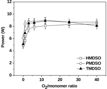
5.1 Electrical characterization of the discharge 64
5.2 HMDSO/Ar/O2 DBDs 67
5.2.1 Effect of gas residence time 67 5.2.2 Effect of the gas feed composition 69
5.3 PMDSO/Ar/O2 DBDs 75
5.3.1 Effect of gas residence time 75 5.3.2 Effect of the gas feed composition 77
5.4 TMDSO/Ar/O2 DBDs 82
5.4.1 Effect of gas residence time 82
5.4.2 Effect of the gas feed composition 84
5.5 Discussion 88
References 91
CHAPTER 6: RESULTS AND DISCUSSION: GAS PHASE ANALYSIS BY GC-MS INVESTIGATION
93
6.1 Optimization of the method 93
6.2 Qualitative analysis of the exhaust 95 6.3 Quantitative analysis of the exhaust 99
6.3.1 Monomer depletion 99
6.3.2 Quantification of silane and siloxane by-products 100 6.3.3 Quantification of silanol by-products 103
6.4 Discussion 104
CONCLUSION (French) 111
ACKNOWLEDGEMENTS
This thesis was developed in the framework of a “co-tutele” between the University of Bari (Italy) and the University Pierre et Marie Curie (France). Different periods were spent at the Department of Chemistry of University of Bari, in the Istituto di Metodologie Inorganiche e Plasmi (IMIP)-CNR, and at the Ecole Nationale Superieure de Chimie Paris (ENSCP) in the Laboratoire de Génie des Procédés Plasma et Traitement de Surface (LGPPTS).
I would like to thank my two supervisors, prof. R. d’Agostino and prof. F. Arefi-Khonsari, and my co-supervisor prof. F. Fracassi, for their guidance in the development of this project. Dr. F. Fanelli is firstly acknowledged for her scientific support and assistance and, secondly, for the XPS and GC-MS analyses.
Finally I would like to express my sincerest gratitude to all ones, in both laboratories, contributed, in whatever way, to the realization of this work and supported me in the entire period of this Ph.D. thesis.
PREFACE
Nowadays textile materials cannot be restricted to clothes, linen, tablecloth and curtains, but they have to be regarded also as high-tech products that, in addition to the traditional clothing industry, find application in many technological fields, like construction, agriculture, automotive, aerospace, medicine. Due to the increasing growth of textile market, in the last decades there is a growing demand for improving the methods for the finishing of textile fabrics as well as of materials with new characteristics. Further the traditional wet techniques are not always environment friendly and at low energy consumption, so dry, environmentally safe, and energetically efficient processes are required as alternatives to the classical/old textile finishing methods. All these issues, along with the statement of fact that some properties are needed only on the textile surface, make non-thermal plasma technologies quite appealing for the textile industry. In particular non-thermal plasma produced at atmospheric pressure are challenging for the modification of the fabrics surface, as this technology is compatible with continuum, on-line processing.
Recently both surface activation and deposition of thin functional coating by means of atmospheric pressure plasma have been investigated in order to confer to textiles various properties, such as affinity for painting and dyeing, stain-resistance, antibacterial, no-shrinking and no-felting character. At this purpose different feeding gas mixtures have been used, from non-polymerizing ones (air, Ar, He, N2, O2), to
hydrocarbon, fluorocarbon and organosilicon precursors. Thin organosilicon coatings, in particular, are quite challenging for various textiles finishing, as, due to their inorganic/organic character, they can exhibit different suitable properties, such as thermal stability, abrasion resistance, anti-reflective character, dielectric and hydrophilic/hydrophobic tuneable features.
This thesis, developed in “co-tutele” between the University of Bari (Italy) and the University Pierre et Marie Curie (France), reports a fundamental study on the deposition of thin organosilicon coating in a Dielectric Barrier Discharge (DBD) which is very interesting for application to the textiles finishing. Although this topic is receiving widespread attention in the scientific community, as stated by the recent literature, very few works investigate organosilicon precursors different from hexamethyldisiloxane (HMDSO) and get inside the occurring deposition mechanism in DBD. The first goal of
this work was the investigation of other precursors: in addition to the HMDSO, pentamethyldisiloxane (PMDSO) and tetramethyldisiloxane (TMDSO) were used as organosilicon monomers. Both gas phase and thin films produced in Ar/HMDSO/O2,
Ar/PMDSO/O2 and Ar/TMDSO/O2 DBD, with different oxidant content, were
investigated with the aim of giving an overview of the three disiloxanes performances. At this purpose a GC-MS detection of by-products in the exhaust gases was carried out and correlated to the coating properties.
The first chapter of this thesis gives an overview of the available plasma processes for the textile treatment, with regard for the atmospheric pressure plasma processes and the employment of organosilicon coating in the textile finishing.
In the second chapter a description of Dielectric Barrier Discharges fundamentals is presented. The third chapter describes the state of the art of organosilicon thin films deposition in both low and atmospheric pressure; a particular attention is given to deposition mechanism investigations.
The experimental apparatus along with the adopted diagnostic techniques are presented in the fourth chapter. The fifth and sixth chapter are respectively devoted to the obtained coatings characterization and to the experimental results from the GC-MS investigations.
INTRODUCTION
A nos jour les matériaux textiles ne sont pas seulement utilisé dans le domaine de l’habillement et les linges de maison (draps, nappes, rideaux, etc.), mais il sont très utilisés comme produits d’une haute technicité employées dans divers domaines industriels, comme la construction, l’agriculture, la médecine, l’industrie aérospatiale et de l’automobile. En raison de la rapide expansion du marché des textiles, l’amélioration des méthodes de finission, ainsi que des matériaux avec des nouvelles propriétés ont été demandées dans les dernières décennies. Par ailleurs les techniques traditionnelles par voie humide sont souvent néfaste pour l’environnement et demandent une consommation d’énergie importante. Les procédés par voie sèche, sans danger pour l’environnement et économiques, constituent une solution alternative aux méthodes traditionnelles. De plus elles permettent de modifier l’extrême surface sans affecter les propriétés massiques des matériaux. Tout particulièrement les plasmas non-thermiques à la pression atmosphérique sont intéressants pour l’industrie textile, car cette technologie est compatible avec la chaîne de production continue.
Récemment l’activation de la surface, ainsi que le dépôt des couches minces fonctionnels par plasmas à la pression atmosphérique, ont été étudiées afin de conférer des nouvelles propriétés aux textiles, comme l’amélioration de l’adhésion vis à vis des peintures et de la teinture, les propriétés tache, antibactérienne, anti-raccourcissement et anti-feutrage. Pour ce faire, une large gamme de précurseur non-polymérisable (air, Ar, He, N2, O2) et polymérisable (hydrocarbures, fluorocarbures,
organosiloxanes), ont été utilisés. En particulier les couches minces obtenues à partir de composés d’organosiloxanes, grâce à leur large gamme de caractéristiques chimiques différentes selon leur caractère, organique ou inorganiques, peuvent conférer des propriétés très intéressantes et variées aux textiles, à savoir la résistance à la chaleur et à l’abrasion, l’isolation électriques, propriétés anti-reflet, ou hydrophobes/hydrophiles.
Cette thèse, développée en co-tutelle entre l’Université de Bari (Italie) et l’Université Pierre et Marie Curie (France), est consacrée à une étude fondamentale de la déposition des couches minces d’organosiloxanes, réalisées par des Décharges à la Barrière Diélectrique (DBD), un procédé très intéressant pour l’application aux textiles. Même si ce sujet est en train de recevoir beaucoup d’attention de la part de la communauté scientifique, la littérature la plus récente étant une preuve, en très peu
d’études des organosiloxanes différents de l’hexaméthyldisiloxane (HMDSO) ont été utilisés comme précurseurs. De plus, jusqu’à présent, les mécanismes du dépôt des couches minces d’organosiloxanes par DBD ont été peu abordés. Le premier but de cette étude a été, donc, d’examiner d’autres précurseurs: outre le HMDSO, tels que le pentaméthyldisiloxane (PMDSO) et le tetraméthyldisiloxane (TMDSO) ont été utilisés. La phase gazeuse, ainsi que les couches minces déposées en DBD alimentées par Ar/HMDSO/O2, Ar/PMDSO/O2 et Ar/TMDSO/O2, avec différentes proportions de
l’oxygène, ont été étudiés dans le but d’avoir une vue d’ensemble des performances des trois disiloxanes utilisés. Pour cette raison les sous-produits générés dans la phase plasma ont été recueillis à partir du gaz sortant du réacteur, et analysés par GC-MS; une corrélation entre les résultats GC-MS et les propriétés des couches minces obtenues a été établi.
Dans le premier chapitre de ce manuscrit nous présentons une introduction sur l’ensemble des procédés plasma disponibles pour le traitement des textiles, avec une attention particulière pour les procédés plasma à la pression atmosphérique et l’utilisation des couches minces d’organosiloxanes comme précurseur.
Le deuxième chapitre est consacré à la description des principes de base des Décharges à la Barrière Diélectrique (DBD). Ensuite nous présentons dans le chapitre 3 l’état de l’art sur les mécanismes du dépôt des couches minces d’organosiloxanes par procédés plasma à basse pression ainsi qu’ à la pression atmosphérique.
Le réacteur DBD et les techniques de diagnostiques utilisés sont présentés dans le quatrième chapitre. L’ensemble des résultats expérimentaux obtenus est présenté dans les chapitres 5 et 6: l’analyse phisico-chimiques des couches minces dans le chapitre 5, et les analyses des gaz sortant du réacteur par GC-MS dans le chapitre 6.
PREFAZIONE
Oggigiorno i materiali tessili non sono utilizzati solamente nel campo dell’abbigliamento e della biancheria per la casa (lenzuola, tovaglie, tende, etc.), ma sono considerati dei prodotti altamente tecnici adoperati in diversi settori industriali, come quelli edile, agricolo, dell’automobile, aeronautico e medico. A causa della forte espansione del mercato tessile, negli ultimi decenni c’è stata una crescente richiesta sia di metodi più efficaci per il finissaggio dei tessuti, sia di materiali con caratteristiche nuove. Inoltre le tecniche tradizionali per via umida non sono sempre eco-compatibili e a basso consumo di energia, perciò la ricerca è rivolta a metodi alternativi a quelli tradizionali, che cioè non utilizzino acqua e/o solventi e che non siano dannosi per l’ambiente. Per tutte queste ragioni, in aggiunta al fatto che spesso alcune proprietà sono necessarie solo sulla superficie di un tessuto, laddove i metodi tradizionali influiscono sull’intero materiale, i plasmi freddi risultano particolarmente interessanti per l’industria tessile. Ancor più interessanti sono i plasmi freddi prodotti a pressione atmosferica, data la loro compatibilità con i processi industriali in continuo.
Recentemente, al fine di conferire ai tessuti diverse proprietà, come l’affinità per la tintura e lo stampaggio, la resistenza alle macchie, il carattere antibatterico, antirestringimento o antinfeltrimento, sono state studiate sia l’attivazione della superficie, sia la deposizione di film sottili mediante plasmi a pressione atmosferica. A questo scopo sono stati usati diversi precursori, dai gas non-polimerizzanti (aria, Ar, He, N2, O2) agli idrocarburi, fluorocarburi, organosilani. I film sottili organosilanici, in
particolare, sono molto indicati per vari finissaggii tessili, poiché, grazie al loro carattere inorganico/organico, possono mostrare diverse proprietà utili al tessile, come la stabilità termica, la resistenza alle abrasioni, il carattere anti-riflesso, isolante, idrofobo/idrofilo.
Questa tesi, sviluppata in co-tutela tra l’Università di Bari (Italia) e l’Université Pierre et Marie Curie (Francia), è uno studio fondamentale sulla deposizione di film sottili organosilanici in Scariche a Barriera di Dielettrico (DBD), molto interessante per l’applicazione ai tessuti. Sebbene questo argomento stia ricevendo molta attenzione dalla comunità scientifica, come provato dalla letteratura recente, pochissimi lavori si occupano di precursori diversi dall’esametildisilossano (HMDSO) e approfondiscono lo studio dei meccanismi di deposizione nelle DBDs. Il primo obiettivo di questo lavoro è
stata l’indagine di altri precursori organosilanici: oltre a l’HMDSO sono stati usati anche il pentametildisilossano (PMDSO) ed il tetrametildisilossano (TMDSO). Allo scopo di fornire una panoramica sulle prestazioni dei tre organosilossani, sono stati studiati sia la fase gas sia i film sottili prodotti in DBD alimentate da miscele gassose di Ar/HMDSO/O2, Ar/PMDSO/O2 ed Ar/TMDSO/O2, con differenti concentrazioni di
ossidante. A tal fine sono stati analizzati i gas esausti delle scariche mediante GC-MS e la loro composizione è stata correlata alle proprietà dei film depositati.
Nel primo capitolo di questa tesi sono brevemente descritti i processi plasmochimici usati per il trattamento di tessuti, in particolare i processi plasmochimici a pressione atmosferica e l’uso di organosilani per il finissaggio.
Nel secondo capitolo sono presentati i principi fondamentali delle Scariche a Barriera di Dielettrico. Nel terzo capitolo è mostrato lo stato dell’arte sulla deposizione di film sottili in plasmi a bassa pressione e pressione atmosferica; particolare attenzione è stata rivolta agli studi sui meccanismi di deposizione.
L’apparato sperimentale e le tecniche diagnostiche impiegate sono descritte nel capitolo 4. Nei capitoli 5 e 6 sono infine presentati i risultati sperimentali relativi, rispettivamente, alla caratterizzazione dei film sottili e alle analisi GC-MS degli esausti.
CHAPTER 1: INTRODUCTION
1.1 General aspects of textile manufacturing
The production of textiles, from fibres to their end products, has a history as long as the human civilization and in the centuries has kept up with it. Nowadays it constitutes a global industry not limited to the apparel marketing, but well linked to many industries, including construction, agriculture, automotive, aerospace, where the unique properties of natural and synthetic fibres, filaments and fabrics are exploited. Textiles for clothing are increasingly becoming high-tech products offering special functionalities, such as hydrophobicity, breathability, UV-stability, flame-protection, antibacterial properties. Anyway these technical textiles comprises not only garments for outdoor sports and safety clothing, but also geotextiles, textiles for architecture, for vehicles or aircrafts (i.e.: reinforcing components, seat belts, airbags), for packaging, filtration, medical and healthcare [1].
The great number of textile chain steps, as sketched in Figure 1.1.1, can be summarized in some main points: the fibres production from natural renewable (plant and animal kingdom) and from synthetic non-renewable sources (petroleum hydrocarbons), the fibres conversion into yarns that are finally employed in the fabrics weave (woven, knitted and tufted fabrics), or their conversion in non-woven fabrics [2]. The production line from the yarn manufacturing to value-added products moves through many wet processes, from the textile pre-treatments, such as desizing, scouring, cleaning, bleaching, to the fabric dyeing and chemical finishing (Figure 1.1.2). At this purpose large amounts of toxic wastewaters are produced [3]. On the other hand some properties (i.e.: the improvement of dyeing process, the stain resistance, antibacterial or antistatic properties etc.) are needed only on the textiles surface, whereas the traditional wet techniques may affect also the intrinsic bulk features, such as comfort, touch, porosity and air/water permeability. Moreover, after a wet chemistry finishing process the textile needs to be dried causing a rise in the productive energetic costs [4]. Therefore dry, environmentally safe, and energetically efficient processes are required as alternatives to classical/old textile finishing methods [5].
In response to this demand, plasma technologies represent eco-friendly, energy efficient and economic alternatives to classical textile finishing processes: they can contribute to make a selection of production based more on quality than on cost, thus reducing the urgency of the problems associated with the global challenge [6].
Figure 1.1.2: Wet processing of woven fabric [3].
1.2 Plasma technologies and textiles
A non-thermal plasma is a partially ionized gas containing high-energy electrons mixed with low-energy molecular species (ions, free radicals, meta-stable excited species, etc.) in a way that the overall system remains close to room temperature. Non-thermal plasma has been intensively studied and applied for the practical industrial requirements on high quality, high productivity, low cost and environmentally clean
modifications may be accomplished through surface activation, ablation, etching, cross-linking, functionalization, film deposition or by some combination of these effects [6, 7].
Since the plasma gas remains at room temperature and textiles are not temperature resistant materials, cold plasma technologies are particularly suited to textile processing. An enormous variety of feeding gases can be used to perform a great number of surface chemistry: a large variety of chemically active functional groups can be incorporated onto the textile surface with the aim of cleaning or disinfecting, or improving wettability, printability, adhesion of coating, or inducing hydro- and/or oleophobic properties, or changing physical features. Further, a plasma treatment can be developed in a wide pressure range, and large reactor chambers and roller systems for large webs, are nowadays available with competitive costs [6].
The earliest plasma processes studies were carried out in low pressure gas systems, however, the integration of these processes, typically running at pressures between 0.1 and 1 mbar, into textile production line is often complex. As a matter of fact vacuum systems are not compatible with continuum, on-line processing and can be used only in batch mode or in semi-continuous vacuum-vacuum-vacuum roll-to-roll systems; additionally vacuum equipments are expensive, so there are high costs also for industrial scale-up. Finally, manufacturers are generally distrustful of vacuum system, mainly for ignorance problems. In the field of textile, in particular, processes are applied to wide areas (fabrics are meters wide and kilometres long) and, moreover, textiles have large specific surfaces: these facts make the desorption/adsorption of gases to become a real problem associated with vacuum systems [4].
Hence non-thermal plasma processes produced at atmospheric pressure are advantageous for the textile industry, as they can be introduced into the production line without major changes or system interruption and they are consistent with fabric large dimensions, high speed and continuous processing. In recent years a number of non-thermal processes, including Plasma Enhanced Chemical Vapour Deposition (PECVD), which were limited to low pressure apparatus, have been successfully transferred to the atmospheric pressure range, making atmospheric pressure plasma usable for substrate pre-treatment, cleaning, etching and plasma chemical coating from either gaseous or liquid precursors. Although the research in the field of low pressure plasma processes
for textiles have not been abandoned [8-12], the scientific world has developed a growing interest for the challenge of atmospheric pressure processes [6, 7].
1.3 Plasma treatments for textiles
As before mentioned plasma phase is made of various chemical species, i.e. electrons, ions, radicals, excited atoms/molecules, UV radiation: by tuning the feeding gas and the process parameters a great number of surface effects could be achieved. This fact well match the complexity of textile chain, as plasma processes could be adopted as any step of the production line, from pre-treatment to finishing.
The surface processes available to the textile industry can be classified as activation, etching/cleaning and coating, but a real distinction between the first two processes is hard to do as they are often contributory factors of the same treatment. Further the different targets in the field of textiles and fibres surface treatment have promoted the development and employment of various plasma apparatus, especially at atmospheric pressure (i.e corona treaters, DBDs system, Atmospheric Pressure Plasma Jet (APPJ)) [13-15].
Ambient air treatments carried out in corona discharges [15-21] on numerous kind of fibres have been widely investigated and compared to processes performed in controlled atmosphere DBDs [22-27] and APPJ [28-30]. The main effect of oxygen containing plasma is the introduction of polar groups, such as hydroxyl, carbonyl, carboxyl, ether, hydroperoxide, that enhance the hydrophilic properties of the treated textiles; anyway oxygen-free plasma create surface active sites that can easily react with ambient air or any other liquid or gaseous environment which the textile is exposed to. These processes often result in a surface energy enhancement aimed at the improving wettability and adhesion properties of the substrate [7, 13, 32].
Wettability is an important parameter for subsequent dyeing or printing of synthetic and natural textiles. Adhesion between fibres and a composite matrix play a fundamental role in composite materials [31-34] and it is involved also in the application of finishing coatings onto fabrics [35-40]. The chemical changes cannot be
micro-roughening that, if it does not turn into a surface damage, strongly improves wettability and adhesion properties of the treated fibres [41-44].
The textiles finishing can be obtained also by the deposition of thin conformal films: plasma promotes both the precursor fragmentation and the creation of surface reactive bonding sites, thus a solid phase material forms at the plasma-surface interface. The PECVD process delivers a dry coating, well-adhered to the substrate and conformal to each individual fibre accessed by the plasma [13]. In atmospheric pressure systems not only gases but also liquids, atomised into droplets and injected in the plasma phase, can be used as thin films precursors [45].
Several examples of PECVD onto fabric can be stated: acrylic acid was plasma polymerized onto polyester and polyamide fabrics to confer them a permanent hydrophilic character [46]; hydrocarbon (ethene, acethylene) and ammonia mixtures were used for the deposition of a-C:H:N coatings in order to introduce and preserve N-containing groups for a long period [47-48]; thin films from plasma fed with fluorocarbon gases were investigated to give water and stain repellence properties [45, 49-51]. Organosilicon compounds are also widely adopted as precursor for the coatings deposition onto fabrics: their suitability for the textile industry will be detailed in the next paragraph.
1.4 Role of silicones in textile finishing
Organosilicon compounds and their derivatives are often non-toxic and easy handling substances widely used in many technological fields. Due to their inorganic/organic character, thin organosilicon coatings can exhibit different properties, from thermal stability to abrasion resistance, anti-reflective character, dielectric and hydrophilic/hydrophobic tuneable properties, that make them suitable for various textiles finishing.
Organosilicon fed plasma result in a complex plasma-phase chemistry and in the tunability of films composition from the silicone-like character, when a great number of organic moieties (CHx) is present in the film, to SiO2-like inorganic coatings, normally
if an oxidant is added to the feeding gas [52]. Silicone-like coatings can exhibit a Water Contact Angle (WCA) up to 110° on flat surfaces, but due to the microstructure of
textile fabrics, knitwear and non-woven, superhydrophobic effects can easily be obtained. Hydrophobic and stain-repellent textiles have a large market impact and are subject to strong demand from textile industry. Among the organosilicon precursor hexamethyldisiloxane (HMDSO) is widely used for the deposition of hydrophobic coatings onto fabric and fibres due to the retention of –CH3 groups within a Si-O
network [53-55].
Organosilicon thin films can confer also high washing permanence and abrasion resistance. HMDSO plasma-polymerized films were recently investigated as anti-pilling finishing for knitted wool fabrics [56]. In another work the barrier properties of HMDSO plasma coating were evaluated in order to control the moisture vapour transmission rate of wound dressings [57]. Other monomers were also investigated: anti-reflective coating layers were deposited onto PET fabrics by means of DBD fed with hexamethyldisilane and tris(trimethylsilyloxy)vinylsilane with the aim of increasing the PET colouring intensity [58].
Organosilicon compounds were also employed in the liquid state onto plasma activated surfaces. In order to obtain stable conductive textiles vinyltrimethoxysilane was grafted onto plasma activated polypropylene and viscose fabrics to ensure a surface covalent bonding of a pyrrole-functionalized silane: the silane back-bone provides a scouring and abrasion resistance to the polypyrrole outer-layer [59]. Hydrogen silicone fluid was grafted onto PET fabrics through corona discharge activation to improve the textile water repellency [60] or onto polyamide fabrics to create a gas-tight airbag [6].
The use of organosilicon substances for textiles treatment cannot be limited to plasma processes. Several studies report on the textiles modification by means of silicon alkoxides sol-gel coatings. The diluted alkoxides can be easily hydrolyzed leading to silanols groups that have a strong tendency to undergo condensation reactions; the basically formed inorganic network can be modified over a wide range by using other additives [1]. Examples could be the investigation of phosphorus doped SiO2 thin films
for giving flame retardancy properties to fabrics [61], the preparation of photoactive transparent thin SiO2-TiO2 films to confer self-cleaning properties to cotton fabrics [62],
REFERENCES
[1] T. Textor, F. Schröter, E. Schollmeyer, NanoS 01.07, 14-17.
[2] S. B. Moore, L. W. Ausley, Journal of Cleaner Production, 12 (2004), 585-601.
[3] E. Kalliala, P. Talvenmaa, Journal of Cleaner Production, 8 (2000), 143-154. [4] T. Stegmaier, A. Dinkelmann, V. von Arnim in, Plasma Techology for
textiles, ed by R. Shishoo, The Textile Institute, WP, 2007.
[5] E. Ozturk, U. Yetis, F. B. Dilek, G.N. Demirer, Journal of Cleaner
Production, 17 (2009), 239-247.
[6] R. Shishoo, Plasma Techology for textiles, ed by R. Shishoo, The Textile Institute, WP, 2007.
[7] R. Morent, N. De Geyter, J. Verschuren, K. De Clerck, p. Kiekens, C. Leys,
Surface & Coating Technology 202 (2008) 3427-3449.
[8] U. Vohrer, M. Müller, C. Oehr, Surface and Coating Technology 98 (1998) 1128-1131.
[9] G. Rosace, R. Canton, Journal of Applied Polymer Science, Vol. 107, 3702– 3706 (2008).
[10] A. Vesel, M. Mozetic, S. Strnad, Z. Peršin, K. Stana-Kleinschek, N. Hauptman, Vacuum 84 (2009) 79–82.
[11] C. Kan, C. M. Yuen, Plasma Processes and Polymers, 2006, 3, 627-635. [12] K. Vaideki, S. Jayakumar, R. Rajendran, G. Thilagavathi, Applied Surface
Science 254 (2008) 2472–2478.
[13] T. Herbert in “Plasma Technology for textiles”, ed by R. Shishoo, The Textile Institute, WP, 2007.
[14] Y. Akishev, M.Grushin, A. Napartovich, N.Trushkin, Plasmas and Polymers, Vol. 7, No. 3, 2002, 261-289.
[15] E. Temmerman, Y. Akishev, N. Trushkin, C. Leys, J. Verschuren, J. Phys. D:
Appl. Phys. 38 (2005) 505–509.
[16] V. A. Titov, E. V. Kuvaldina, S. A. Smirnov, A. N. Ivanov, V. V. Rybkin,
High Energy Chemistry, Vol. 36, No. 2, 2002, pp. 121–125.
[18] A. V. Ulesova, A. A. Grechko, S. F. Sadova, Fibre Chemistry, 40, 2, 2008, 143-146.
[19] S. Nourbakhsha, M. E. Yazdanshenas, Color. Technol., 124, 43–47 (2008). [20] X. Wang, G. Cao, W. Xu, Journal of Applied Polymer Science, 112, 1959–
1966 (2009).
[21] P. Ma, X. Wang, W. Xu, G. Cao, Journal of Applied Polymer Science, 114, 2887–2892 (2009).
[22] G. Borcia, C.A. Anderson, N.M.D. Brown, Surface & Coatings Technology 201 (2006) 3074–3081.
[23] N. De Geyter, R. Morent, C. Leys, Surface & Coatings Technology 201 (2006) 2460-2466.
[24] Y. Shin, K. Son, D. I. Yoo, S. Hudson, M. McCord, S. Matthews, Y.-J. Whang, Journal of Applied Polymer Science, 100, 4306–4310 (2006). [25] H. A. Karahan, E. Özdoğan, A. Demir, H. Ayhanb, N. Seventekin, Color.
Technol., 124, 106–110 (2008).
[26] C. Zhang, K. Fang, Surface & Coatings Technology 203 (2009) 2058–2063. [27] N. Yaman, E. Özdoğan, N. Seventekin, H. Ayhan, Applied Surface Science
255 (2009) 6764–6770.
[28] Y. Ren, C. Wang , Y. Qiu, Surface & Coatings Technology 202 (2008) 2670– 2676.
[29] C.X. Wang , H.L. Xu , Y. Liu, Y.P. Qiu, Surface & Coatings Technology 202 (2008) 2775–2782.
[30] H. Xu, S. Peng, C. Wang, L.Yao, J. Sun, F. Ji, Y. Qiu, Journal of Applied
Polymer Science, 113, 3687–3692 (2009)
[31] C. Canal, F. Gaboriau, R. Molina, P. Erra, A. Ricard, Plasma Processes and.
Polymers, 2007, 4, 445–454.
[32] I. Holme, International Journal of Adhesion & Adhesives 19 (1999) 455-463. [33] Y. Kusano, H. Mortensen, B. Stenum, P. Kingshott, T. L. Andersen, P.
Brøndsted, J.B. Bilde-Sørensen, B.F. Sørensen, H. Bindslev, Plasma
[35] M.J. Tsafack, J. Levalois-Grützmacher, Surface & Coatings Technology 200 (2006) 3503– 3510.
[36] M. Okubo, N. Saeki, T. Yamamoto, Journal of Electrostatics 66 (2008) 381– 387.
[37] J.-D. Liao, C. Chen, Y.-T. Wu, C.-C. Weng, Plasma Chemistry and Plasma
Processing, 25, 3, June 2005.
[38] F. Hochart, R. De Jaeger, J. Levalois-Gru¨tzmacher, Surface and Coatings
Technology 165 (2003) 201–210.
[39] D. Hegemann, Advanced Engineering Materials, 2005, 7, 5, 401-404. [40] W.-H. Yao, J.-C. Chen, C.-C. Chen, Polym. Adv. Technol. 2008, 19, 1513–
1521.
[41] R. Molina, J.P. Espinós, F. Yubero, P. Erra, A.R. González-Elipe, Applied
Surface Science 252 (2005) 1417–1429.
[42] J. Yip, K. Chan, K. M. Sin, K. S. Lau, Applied Surface Science 253 (2006) 2493–2497.
[43] C. Kan, C. M. Yuen, Journal of Applied Polymer Science, 102, 5958–5964 (2006).
[44] K. K. Samanta, M. Jassal, A. K. Agrawal, Surface & Coatings Technology 203 (2009) 1336–1342.
[45] F. Leroux, C. Campagne, A. Perwuelz, L. Gengembre, Applied Surface
Science 254 (2008) 3902–3908.
[46] A. Cireli, B. Kutlu, M. Mutlu, Journal of Applied Polymer Science, 104, 2318–2322 (2007).
[47] M. M. Hossain, A.S. Herrmann, D. Hegemann, Plasma Process. Polym. 2007, 4, 135–144.
[48] M. M. Hossain, D. Hegemann, G. Fortunato, A. S. Herrmann, M. Heuberger,
Plasma Process. Polym. 2007, 4, 471–481.
[49] J. Zhang, P. France, A. Radomyselskiy, S. Datta, J. Zhao,W. van Ooij,
Journal of Applied Polymer Science, 88, 1473–1481 (2003).
[50] M. G. McCord, Y. J. Hwang, Y. Qiu, L. K. Hughes, M. A. Bourham, Journal
[51] D. Sun, G.K. Stylios, Journal of Materials Processing Technology 173 (2006) 172–177.
[52] A.M. Wróbel, M.R. Wertheimer in Plasma deposition, treatment and etching
of polymers, R. d’Agostino ed., Academic Press, New York 1990, p.163
[53] H. Höcker, Pure Appl. Chem., 74, 3, pp. 423–427, 2002. [54] D. Hegemann, D. Balazas, NanoS 01.07.
[55] Y. Y. Ji, H. K. Chang, Y. C. Hong, S. H. Lee, Current Applied Physics, 2009, 9, 253-256.
[56] F. Rombaldoni, R. Mossotti, A. Montarsolo, M. B. Songia, R. Innocenti, G. Mazzuchetti, Fibers and Polymers 2008, 9, 5, 566-573.
[57] X. J. Dai, J. S. Church, M.G. Huson, Plasma Process. Polym. 2009, 6, 139– 147.
[58] H.-R. Lee, D. Kim, K.-H. Lee, Surface and Coatings Technology 142-144 (2001) 468-473.
[59] M. Mičušík, T. Nedelčev, M. Omastová, I. Krupa, K. Olejníková, P. Fedorko, M. M. Chehimi, Synthetic Metals 157 (2007) 914–923.
[60] J. Lei, M. Shi, J. Zhang, European Polymer Journal 36 (2000) 1277-1281. [61] A. Cireli, N. Onar, M. F. Ebeoglugil, I. Kayatekin, B. Kutlu, O. Culha, E.
Celik, Journal of Applied Polymer Science, 105, 3747–3756 (2007).
[62] T. Yuranova, R. Mosteo, J. Bandara, D. Laubb, J. Kiwi, Journal of Molecular
Catalysis A: Chemical 244 (2006) 160–167.
[63] C. Schramm, W.H. Binder, R. Tessadri, Journal of Sol-Gel Science and
Technology 29, 155–165, 2004.
[64] C. Schramm, B. Rinderer, W.H. Binder, R. Tessadri, H. Duelli, Journal of
CHAPTER 2: ATMOSPHERIC PRESSURE PLASMA AND DIELECTRIC BARRIER DISCHARGES
2.1 Generalities about plasmas
Plasma is a partially ionized gas made of electrons, ions and neutrals in fundamental and excited states; although it is electrically conductive due to the presence of free charge carriers, from a macroscopic point of view plasma is electrically neutral. Excited species can undergo radiative relaxation processes emitting light in the visible-UV region, thus plasma is usually characterized by a glare: flames, lightnings, the aurora borealis, solar corona, interstellar space are some of the numerous examples of natural plasma. Anyway plasma can be artificially generated by giving energy to a gas by means of heat, radiation, electric or magnetic field: examples are the neon tube and the plasma display panels [1-3].
On the base of electron density and gas temperature, plasmas are generally classified in equilibrium and non-equilibrium plasmas. In equilibrium plasmas the high number of elastic collisions occurring between electrons and neutral species, that constitute the main part of the gas phase, promotes the enhancement of neutral kinetic energy. As a consequence the heavy particles in the plasma achieve the same electrons temperature (~104 K), so this kind of plasma is also called thermal plasma. Due to their high temperature thermal plasmas are used for elemental spectroscopic analysis and for industrial processes like welding, cutting and waste destruction.
In non-equilibrium plasmas, instead, high energy electrons are involved in few elastic collisions, whereas they result quite effective in anelastic collisions, thus producing excited species, radicals and ions: electrons remain the more energetic species in the plasma (~ 10 eV), while heavy particles, if compared to the fast electrons, could be considered static, so their translational temperature remain close to the ambient one (~300 K). As heavy particles are the most abundant species in the plasma, they also determine the plasma temperature: for this reason non-equilibrium plasmas are also called cold plasmas. Non-equilibrium plasmas are widely used as surface modification technique, also for thermally unstable materials like polymers, paper, textiles, etc., and
have found application also in pollution control, volatile organic compounds removal, ozone generation and lamps [1, 3-4].
The working pressure play a fundamental role in determining the plasma temperature: at pressures lower than 10 Torr non-equilibrium plasmas are easily generated due to the large particles mean free path and, consequently, few electron-neutral elastic collisions; at higher pressures collisions become more frequents, therefore plasma temperature approaches the electrons one (Figure 2.1.1). Since the 70th cold plasmas generated in low pressure discharges (some hundred of mTorr), with regard to radio frequency (13.56 MHz) and microwave (2.54 GHz) plasmas, have been widely investigated. More recently new technical solutions allowed to obtain non-thermal plasmas at atmospheric pressure. In the last decade great attention has been paid to the atmospheric plasma technology as it can overcome some vacuum systems drawbacks that limit the plasma processes scale up, thus resulting very attractive for many industrial applications [5-8].
Figure 2.1.1: Evolution of electrons and heavy particles temperature as a function of
2.2 General aspects of atmospheric pressure plasmas
Non-thermal plasmas at atmospheric pressure can be generated by various type of electrical discharges. Their main feature is the production of high energy electrons promoting the formation of chemically active species, while the gas molecule remain cold. Different approaches can be used to maintain the neutral species at low temperature, that is limiting the input energy adsorbed in the discharge, providing an efficient cooling of the plasma stream or decreasing the residence time of the gas in the discharge gap [5-6, 8].
Many authors conveniently classify atmospheric pressure discharges on the base of applied excitation frequency and three main groups are defined: the direct current (DC) and low frequency alternating current discharges (1-100 kHz range), the radiofrequency discharges (100 kHz -100 MHz), the microwave (MW) discharges (>100 MHz) [5-7].
In the perspective of atmospheric pressure plasma sources developed for the surface treatment and the deposition of thin films (PECVD), probably due to the difficulty of designing a convenient equipment for wide areas coverage and sustaining MW discharges at low power avoiding high plasma temperatures [6], very few examples of MW sources working at atmospheric pressure can be found, mainly operating in a remote system configuration [9-10]. The Atmospheric Pressure Plasma Jet (APPJ), the cold plasma torch and the hollow cathode systems are the main type of RF plasma sources adopted for the AP-PECVD processes. Here plasma is generated in a narrow inter-electrode gap, normally with coaxial geometry, and it is blown outside that region by gas flow directly onto the substrate: the plasma treatment or deposition thus occurs in downstream mode [7, 11]. These systems have been investigated for the deposition of oxides onto small and large surfaces [6, 12-13].
The DC and low frequency discharges can work in continuous and pulsed mode. Pulsed DC power supplies are adopted for Corona Discharges, that are generated in highly asymmetric electrodes configuration, like sharply pointed needle or thin wire opposing flat planes or large diameter cylinder (Figure 2.2.1): when a high voltage is
HV HV a) b) HV HV HV HV HV HV HV a) b)
Figure 2.2.1: Corona systems: a) point-to-plane geometry; b) wire-to-plane geometry.
applied to the smaller electrode an intense electric field is generated around it, so plasma ignites in the form of streamers. Although this kind of discharges has been scaled–up for open-air surface modifications, the plasma volume is very small and streamers mainly generate in the same place, limiting its application to narrow areas and causing often non–homogeneous treatments [7, 11]. These drawbacks have been partially overcome by DBDs, characterized by the insertion of a dielectric layer in the discharge path; as a consequence, they operate at low frequencies alternating currents. DBD technology is quite appealing for industries as DBDs work at atmospheric pressure, at strongly non-equilibrium conditions, and at reasonably high power levels, with the use of simple design and relatively simple power supplies [7, 11, 14-16].
It is worth mentioning that some DBD systems are referred as Corona Treaters because plasma industry has developed equipments having the corona plasma type’s asymmetric electrode configuration, typically a metal rod opposing a large diameter metal cylinder, together covered with the DBD’s dielectric, generally ceramic (Figure 2.2.2): these systems run a hybrid corona/DBD plasma type adopted for large web treatment [11].
Dielectric Conducting
electrodes
Web HV
Figure 2.2.2: Schematic of a corona treater (adapted from reference 11).
2.3. Historical background of Dielectric Barrier Discharge
Although only in recent years scientific community has shown a growing interest for DBDs and their possible application in different technological fields, this kind of discharge has a long history [17]. Its birth is ascribed to Werner von Siemens who in 1857 developed a new discharge tube for the ozone production (Figure 2.3.1), whose novelty was that electrodes were positioned outside the discharge chamber and, thus, they were not in contact with the plasma: an oxygen or air flow was forced in an annular gap between two coaxial glass tubes, and an alternating voltage sufficiently high to promote the electrical gas breakdown was applied to two external coaxial electrodes [18]. As the electric current was forced to pass through the tube glass walls acting as dielectric barrier, nowadays this kind of discharge is commonly referred to as Dielectric Barrier Discharge, but in the first time it was called Silent Discharge due to the absence of sparks, usually accompanied by local shock waves and noise [19].
Figure 2.3.1: Historic ozone discharge tube of W. Siemens [17-18].
After the experimental investigation of Siemens for many decades interest for DBDs was mainly focused on their suitability for ozone production at industrial level [20-22]. At the beginning of 20th century various studies on the nature of the DBDs were carried out. Among them the work made by the electrical engineer K. Buss is worth of notice: in 1932 he found that when a planar parallel electrode system with dielectric layer on both electrodes is used at atmospheric pressure, the air breakdown occurs in a large number of tiny short lived current filaments; moreover he was able to take the first photographic traces, called Lichtenberg figures, of these microdischarges, and the current-voltage oscilloscope recordings [23]. Other authors [24-29] investigated the nature of these current filaments and in 1943 T. C. Manley proposed a method for the evaluation of dissipated power in the DBDs based on closed voltage/charge Lissajous figures and derived the power formula for ozonizers [30].
For many years, up to 80th, great efforts for the ozone production by DBDs were done, but around 1970 researchers started to adopt modern diagnostic and modelling tools for a better understanding of plasma physical and chemical processes in ozonizers: these efforts have resulted not only in an improvement of ozone production technology, but also in the extension of DBDs application fields. Nowadays, indeed, DBDs are widely used also in pollution control, in excitation of CO2 lasers and excimer lamps, in
flat plasma display panels, for surface treatments especially in the web conversion industry, and result quite appealing for the deposition of thin films in low-temperature atmospheric pressure plasmas [14-17, 31-35].
HV Pyrex bell-jar Electrode Electrode a) b) Glass plate
Figure 2.3.2: Schematic of the reactors employed by Kogoma and co-workers [37-40]:
a) plane-style upper electrode; b) brush-style upper-electrode.
An important advance in the DBDs technology has been the achievement of homogeneous discharges also at atmospheric pressure. For a long time it was believed that uniform glow discharges could be produced only at low pressure, as the known discharges at atmospheric pressure were not homogeneous. The first evidence of a glow discharge at atmospheric pressure was recorded by von Engel in the 1933 [36], who used cooled metal electrodes in hydrogen gas. Anyway the research in the field of homogenous DBDs really started in the 1987 with the studies carried out by Kogoma and co-workers [37-40]. They developed an experimental set-up devoted to obtain a stable uniform discharge, that they named atmospheric-pressure glow (APG), avoiding in the same time the transition to an arc discharge. They stated that some requirements needed: a) the use of helium as main gas, also if later they obtained an APG with argon/acetone mixtures, too; b) the use of a high-frequency source, in the kilohertz or radio frequency range; c) an insulating plate on the lower electrode or on the bottom of the upper electrode depending on the reactor geometry adopted: the APG were, indeed, produced in a Pyrex bell jar containing a plate lower electrode, acting also as sample
holder, and, at the bottom, a brush-style electrode, made of sharp-pointed fine tungsten wires, for the treatment of dielectric materials, or another plate electrode for electrically conductive substances (Figure 2.3.2). By using fine wire mesh electrodes, a 50 Hz source and suitable dielectric plates, they obtained stable homogeneous glow discharges also in argon, nitrogen and air [40].
Other authors investigated the nature of homogeneous discharges produced at atmospheric pressure. F. Massines and co-workers gave a strong input in understanding homogeneous regimes by experimental and theoretical methods. They mainly studied helium and nitrogen discharges and they found that in He sub-normal discharges, very similar to normal glow discharges, are produced, while in N2 a Townsend-like
mechanism occurs [41-46].
Independently of these activities in 1995 J.R. Roth and co-workers developed a uniform glow discharge, named One Atmosphere Uniform Glow Discharge Plasma (OAUGDP), produced in atmospheric pressure air and other different gases [47-48].
Up to now several teams have focused their research activity on spectroscopic and electrical measurements as well as on the development of theoretical models aimed to a better understanding of the DBDs physic and chemistry, but great efforts are done also in the fields of numerous applications with the aim of the industrial scale up.
2.4 Fundamentals on DBDs 2.4.1 General description
By definition a Dielectric Barrier Discharge device is characterized by one or more dielectric layers located in the current path between two metal electrodes. Ceramics, glass, quartz, polymer layers or other material of low dielectric loss and high breakdown strength are used as dielectric barriers. Due to the presence of an insulating material capacitively coupled with the gas gap, DBDs require alternating voltages. Driving voltages from few hundred volts to several kilovolts with frequencies in the 50 Hz – 500 kHz range are normally used [8, 17]; some examples of DBDs generated at
The dielectric role in the DBD set-up is to avoid the arc formation by limiting the average current density in the gas space. The amount of displacement current that can be passed through a dielectric depends on its dielectric constant, thickness and on the time derivative of the applied voltage, dV/dt. As a consequence of the presence of an insulator and the use of alternating voltage, DBDs are always pulsed discharges.
When electrical breakdown occurs in most gases a large amount of microdischarges, distributed in the discharge gap, appears: this discharge regime, that is also the most common DBD mode, is called filamentary regime. Under certain experimental conditions, depending on the gas mixtures, electrode configurations and operating parameters, homogeneous regimes, the so-called glow-discharges, can be obtained. Moreover apparently homogeneous, diffuse discharges and regularly spaced glow discharges patterns have been observed [8, 17, 50].
2.4.2 DBD apparatus
On the base of the application field different electrode configurations are available in literature, as shown in Figure 2.4.1 [8, 15-17]. The cylindrical geometry is widely used for CO2 lasers, UV excimer lamps, for ozone and gas synthesis, and for
depollution of gas streams. For the environmental control processes the packed-bed configuration is also extensively used: the interelectrode gap is filled with dielectric pellets, so a non-equilibrium plasma is generated in the voids between them [8]. Planar arrangements, with one or both electrodes covered by a dielectric, are mainly adopted for the surface treatment and the deposition of thin films. In cylindrical and planar geometries a volume discharge in the electrode gap is obtained, while in the coplanar and surface electrode geometry, mainly adopted in plasma display panels, discharge develops as a thin layer onto the dielectric surface, the so-named surface discharges [51].
a)
b)
d)
Packed bed reactor
c)
Figure 2.4.1: Basic DBD electrode configurations [8, 16].
The electrode gap, which typically varies from 0.1mm to several centimetres, is filled with gas at atmospheric pressure. The working gas can either flow through the gap as for surface treatment, pollution control and ozone production, or it can be
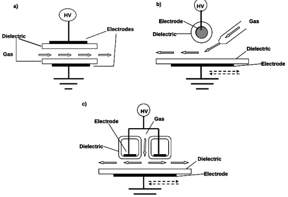
The electrode geometry and the related gas injection systems adopted for surface treatment and PECVD, and based on the planar arrangement, can be further detailed and are sketched in Figure 2.4.2 [52-53]. The basic geometry employed in deposition processes is a parallel plate configuration where identical electrodes are both covered by a dielectric layer; a lateral gas injection, where feeding gas is introduced in the discharge gap by means of an inlet slit and is pumped out in the opposite side, is normally adopted with this system (Figure 2.4.2a) [41-46, 54].
HV Electrodes Dielectric Gas a) HV Dielectric Electrode Dielectric Electrode Gas b) Dielectric Electrode Dielectric Electrode Gas HV c) HV Electrodes Dielectric Gas a) HV Electrodes Dielectric Gas a) HV Dielectric Electrode Dielectric Electrode Gas b) HV Dielectric Electrode Dielectric Electrode Gas HV Dielectric Electrode Dielectric Electrode Gas HV Dielectric Electrode Dielectric Electrode Gas b) Dielectric Electrode Dielectric Electrode Gas HV c) Dielectric Electrode Dielectric Electrode Gas HV Dielectric Electrode Dielectric Electrode Gas HV HV HV c)
Figure 2.4.2: Typical DBD electrode configuration adopted for PECVD.
Other approaches adopt an asymmetric geometry and the movement of the larger electrode, generally the grounded one, in order to overcome some drawbacks of the lateral gas injection, such as the possible variation of coating thickness and chemical composition as a function of the gas residence time in the discharge area. In such systems the high voltage (HV) electrode can be a cylindrical metallic rod covered by a coaxial dielectric tube, so the gas is injected through a gas diffuser faced with the discharge region (Figure 2.4.2b) [55-56], or it can be made of two identical HV
electrodes symmetrically placed respect to the gas injection slit in a way that the gas is introduced from above (Figure 2.4.2c) [57-58]; the grounded electrode is usually a large plate, covered by a dielectric, that acts as sample holder and moves back and forward at controlled speed in order to ensure homogeneous thin films deposition over large areas. In the case of filamentary DBDs, in particular, the substrate movement is a technical solution to reduce the surface exposure to microdischarges that could cause a lack of homogeneity and surface damage. This same approach is used in roll-to-roll systems, like the before mentioned corona treaters (Figure 2.2.2), employed for the treatment of polymeric webs as continuous in-line processes [11, 16-17].
2.5 Dielectric Barrier Discharge regimes
Dielectric Barrier Discharges are usually classified in two main categories: the filamentary discharges (FDBDs) and the glow discharges (GDBDs). Different discharge regimes arise from different electrical breakdown mechanisms, that is the formation of a conductive gas channel caused by an applied electric field more intense than a critical value. In spite of differences among the breakdown mechanisms, all usually start with an electron avalanche, that is the multiplication of some primary electrons in a cascade ionization [8].
At the typical pressure-gas gap product (P x d) in an atmospheric pressure DBD the electron mean free path is very small in comparison with the gas gap, so an electron can generate a large size avalanche resulting in the streamer breakdown mechanism. A streamer is a thin ionized channel growing fast between electrodes; the condition of streamer formation, also called Meek’s condition, is fulfilled when the space charge of a primary electron avalanche is large enough to create an electric field with a strength comparable to the applied electric field [59]. When a streamer breakdown occurs microdischarges are generated, thus the discharge works in the filamentary regime [8, 15-17, 50]
In particular experimental conditions, depending on the feeding gas and the working frequency and voltage, a Townsend breakdown can occur. This ignition mechanism
electron emission: primary electrons, generated near the cathode and drifting to the anode, produce positive ions that, moving back towards the cathode, knock out secondary electrons; as soon as the electric field becomes high enough, the breakdown occurs and a self-sustaining discharge is initiated. This mechanism well explain the ignition of low-pressure glow discharges [59]; when a Townsend breakdown occurs at atmospheric pressure the discharge works in the glow regime [41-46].
2.5.1 Filamentary DBD
The filamentary regime is the most common DBD operational mode and it was the first to be observed in atmospheric pressure discharges. In filamentary DBDs the electrical breakdown starts almost simultaneously at many points of the surface and proceeds with the development of a large number of short-lived microdischarges, each one generated from a streamer breakdown. An initial electron, starting from some point in the discharge gap, produces secondary electrons by direct ionization and develops an electron avalanche and, if the Meek’s condition is fulfilled, a streamer. The streamer bridges the gap in few nanoseconds and forms a conducting channel, typically of about 100 μm radius, of weakly ionized plasma; intense electron current flows through this channel, promoting ionization, until the local electric field collapses. As a matter of fact electrons deposit onto the anode dielectric barrier causing a charge accumulation and dissipate from the gap in about 40 ns, while heavy ions remain in the gap for some microseconds: the charges accumulated on the dielectric surface and the ionic space charge cause the collapse of the local electric field, thus the streamer extinction. A microdischarge is the group of local processes occurring in the discharge gap from the electron avalanche until the end of electron current [8, 15-17, 50]. Typical characteristics of DBDs microdischarges in air are summarized in Table 2.1.
Table 2.1: Characteristic micro-discharge properties in a 1mm gap
atmospheric-pressure air [8, 16, 50].
Duration time 1-10 ns Filament radius about 0.1 mm Peak current 0.1 A
Current Density 100-1000 A cm-2 Total Charge 10-10-10-9 C Electron density 1014-1015 cm-3 Electron energy 1-10 eV
The charge accumulation onto the anode dielectric barrier prevents the formation of new streamers nearby until the voltage polarity reverses, but at the same time promotes new avalanches and streamers in the same spot when the voltage polarity reversal occurs. When the electron current stops, the excited species and ionic charges remain in the microdischarge channel volume and slowly move to the electrodes resulting in a low and long falling ion current; this ion current along with the charges deposited onto the surface, define a region in the discharge gap, called microdischarge remnant, that facilitate the formation of new microdischarges in the same spot as the voltage polarity reverses. The fact that the microdischarge remnant does not dissipate before a new microdischarge starts is called the memory effect and its main consequence is that in DBDs single filaments can be observed: a filament is, indeed, a group of microdischarges forming on the same spot at each polarity reversal [8].
The microdischarges properties does not depend on the external circuit, but only on the gas composition, pressure and electrode configuration; a power increase just leads to a larger number of microdischarges per unit time and per unit of electrode area. As in the remnant region external electric field is perturbed, at rising external voltage other microdischarges preferentially strike at other locations outside the area of influence of the previous microdischarge. This experimental evidence suggests that in DBDs dielectric has two roles: it limits the amount of energy injected in a single
Due to the short duration of the microdischarges and their small volume in comparison with the entire gas gap, plasma remains strongly non-thermal. The charge accumulation on the dielectric surface promotes the current termination just several nanoseconds after the breakdown, thus a very low overheating of the streamer channel occurs. Moreover the gas in between the microdischarges is not ionized and serves as background reservoir to absorb the energy dissipated in the microdischarges and to collect and transport the created long-lived species [15-17, 50].
Although microdischarges are randomly distributed in the space and in time, microdischarge patterns, due to the mutual influence of microdischarges in a DBD, have been also observed. The mechanism of influence arise from the net positive charge of the plasma channel and microdischarge remnant due to the faster motion of electrons respect to heavy ions: positive charges reduce the electric field in the anode area, thus preventing the formation of neighbouring microdischarges. A typical repulsion distance between microdischarges cause the observation of a short-range order in their distribution. When the average distance between microdischarges is larger than the characteristic interaction radius, or at AC frequencies too low or too high (megahertz), no significant microdischarges interaction is observed [8, 60].
2.5.2 Glow DBD
As previously stated in the recent years other discharge regimes, with no evidence of microdischarges, have been also observed and widely investigated. A this purpose the electrical characterization of the discharge, with regard to the current-voltage (i-V) recordings, are a powerful tool. When a filamentary discharge occurs multiple current pulses per half cycle are observed; Figure 2.5.1a shows the current and voltage waveform of a filamentary DBD. Diffuse and homogeneous discharges, instead, exhibit a current waveform with a single pulse per half cycle, but a distinction should be done between a homogeneous appearance and a really glow regime: in glow discharges the single pulse has also always the same intensity and periodicity as the applied voltage, as shown in Figure 2.5.1b; anyway a single pulse is not sufficient to prove the homogeneity of a discharge, as, if there is a very large number of streamers generated in way that they spatially overlap and the instrument cannot resolve very narrow current pulses, a wide single pulse can be showed [39-44, 50].
b) a)
Figure 2.5.1: Typical oscillograms of the sinusoidal voltage and pulsed current in a) a
FDBD in He at1 kHz excitation frequency, b) a GDBD in He at 10 kHz excitation frequency [42].
lifetime (1-10ns) show a uniform region extending uniformly over the whole electrode surface in the case of glow discharges, while several localized discharges are visible for a filamentary discharge [41-45, 50]. Studies on pure gas GDBD carried out by Whertheimer and co-workers revealed that the homogeneous character of a discharge is proved by the total light emission signal from the gap and for a glow discharge a periodicity is recorded. Further in helium they observed a multi peak-regime, that they called pseudo-glow regime, as the discharge current is always periodical, but is formed by more than one current peak per half-cycle, each peak corresponding to a new discharge [61-62].
As reported in the paragraph 2.3 Kogoma and co-workers reported on the generation of an atmospheric pressure glow discharge (APGD) in helium and gave the necessary condition to obtain it, along with the evidence of the periodicity of the discharge current signal. Massines and co-workers confirmed these results and carried out several studies on the occurrence of glow discharges at atmospheric pressure in different atmospheres, with particular regard for helium and nitrogen. They proved that in helium and in noble gases subnormal glow discharges can be obtained, while in nitrogen Townsend discharges occur. Both these discharges at low pressure are generated by a Townsend breakdown, so Massines and co-workers stated that at atmospheric pressure only a Townsend breakdown can generate a glow discharges [42, 45].
Some conditions should verify to obtain a Townsend breakdown at atmospheric pressure: a high number of seed electrons, an ionization mechanism under low fields, a high value of the dielectric secondary emission coefficient. The condition to avoid streamers formation is the ability to produce electrons in small electric field in order to avoid a fast growth of electron avalanche. As an intense space-charge is not generated, ions have time to reach the cathode to promote the secondary electrons emission, so an increase of ion density is also necessary. Besides the electron-neutral collisions, metastables species play an important role in promoting ionization by Penning effect. It was found that in noble gases small amounts of impurities enhance the Penning effect thus promoting a glow discharge. On the other hand higher quantity of impurities can lead to the transition from a glow to a filamentary discharge [41].
An increase of the ionization and of the number of electrons emitted from the cathode is not sufficient to ensure a glow regime as also the number of electrons
remaining in the gas before the occurrence of a new discharge is quite important. As these electrons arrive at the insulator surface under low electric fields, they are slightly trapped: this is the so called memory effect. These electrons can be easier released in the next half period enhancing the value of secondary cathode emission and thus enhancing the probability of obtaining a glow discharge [41].
As before mentioned a Townsend breakdown generates a glow or a Townsend discharge: in glow discharges the memory from one discharge to the following one is based on electrons and ions trapped in a positive column formed during the discharge, and current densities of the order of mA/cm2 are obtained; in a Townsend discharge gas metastables create electrons through cathode secondary emission and current densities are very low [45-46]. In comparison with value reported for micro-discharges (Table 2.1), in a diffuse discharge the number of electrons and their energy are in the 109-1011 cm-3 and 0.2-0.5 eV ranges, respectively [50].
![Figure 2.1.1: Evolution of electrons and heavy particles temperature as a function of the pressure in a mercury plasma arc [7, 50]](https://thumb-eu.123doks.com/thumbv2/123doknet/7765604.255884/32.892.329.707.507.765/figure-evolution-electrons-particles-temperature-function-pressure-mercury.webp)

![Figure 2.3.2: Schematic of the reactors employed by Kogoma and co-workers [37-40]:](https://thumb-eu.123doks.com/thumbv2/123doknet/7765604.255884/37.892.158.589.164.451/figure-schematic-reactors-employed-kogoma-workers.webp)
![Figure 2.5.1: Typical oscillograms of the sinusoidal voltage and pulsed current in a) a FDBD in He at1 kHz excitation frequency, b) a GDBD in He at 10 kHz excitation frequency [42]](https://thumb-eu.123doks.com/thumbv2/123doknet/7765604.255884/46.892.273.804.531.762/figure-typical-oscillograms-sinusoidal-excitation-frequency-excitation-frequency.webp)
![Figure 3.2.1: General deposition mechanism in low pressure organosilicon fed plasma [47]](https://thumb-eu.123doks.com/thumbv2/123doknet/7765604.255884/55.892.118.644.397.658/figure-general-deposition-mechanism-low-pressure-organosilicon-plasma.webp)

![Figure 4.2.2: Electrical equivalent circuit corresponding to the DBD system employed in this study, adapted from references [1, 4-5]](https://thumb-eu.123doks.com/thumbv2/123doknet/7765604.255884/72.892.266.782.111.362/figure-electrical-equivalent-circuit-corresponding-employed-adapted-references.webp)