O
pen
A
rchive
T
OULOUSE
A
rchive
O
uverte (
OATAO
)
OATAO is an open access repository that collects the work of Toulouse researchers and
makes it freely available over the web where possible.
This is an author-deposited version published in :
http://oatao.univ-toulouse.fr/
Eprints ID : 13181
To cite this version : Coelho, Rodrigo and Fohler, Gerhard and
Scharbarg, JeaLuc Worst-case backlpg for AFDX network with
npriorities. (2014) In: International Workshop on RealTime Networks
-RTN 2014, 8 July 2014 - 8 July 2014 (Madrid, Spain).
Any correspondance concerning this service should be sent to the repository
administrator:
[email protected]
Worst-case backlog for AFDX network with
n-priorities
Rodrigo Coelho, Gerhard Fohler
Technische Universit¨at Kaiserslautern, Germany {coelho, fohler}@eit.uni-kl.de
Jean-Luc Scharbarg
Universit´e de Toulouse - IRIT/INP-ENSEEIHT [email protected]
Abstract—In most recent avionics systems, AFDX (Avionics Full Duplex Switched Ethernet) is the network used to replace the previously employed point-to-point networks. AFDX guarantees bandwidth reservations by means of virtual links which can be classified with two priority levels. AFDX compliant switches implement output buffers at each switch output port. The stored frames leave each output port according to a fixed priority FIFO policy. Overflow of these buffers must be avoided at all cost to prevent data loss. Although the AFDX standard determines the minimum buffer size dedicated to an output port, the actual length of each priority buffer, is a designer decision.
Previous works address the worst case backlog of ADFX buffers of one and two priorities. In this work we assume an extended AFDX network in which virtual links can be classified into n-priorities and present the problem statement to compute an upper bound on the worst case backlog faced by each buffer of each output port in each switch of the network.
I. INTRODUCTION
In most recent avionics systems, the switched ethernet net-work AFDX [1] (ARINC 664 Part-7), is chosen to substitute the point-to-point connections of previous avionics distributed systems. Currently, AFDX offers a network bandwidth of 100Mbps and allows for bandwidth isolation among all net-work traffic by employing the concept of virtual links (VL).
A VL defines a logical path from one source end-system (ES) to one or more destination ESs. The physical route for each VL is statically defined at design time and therefore the switches traversed by each VL are known before run-time. The predictable behavior of AFDX is further ensured by the parameters BAG and Smax, respectively bandwidth allocation
gap (minimum time interval between the transmission of two consecutive frames of a VL) and maximum frame size associ-ated with a VL. AFDX further allows for the classification of VLs into two priority levels: high and low.
AFDX compliant switches perform store-and-forward. In order to cope with contention for the switches output ports, each output port offers one FIFO queue per priority level. Due to the fixed priority FIFO scheduling at the output ports, switches have to send all frames with high priority before the low priority ones. Considering the non-preemptive property of frame scheduling, a switch cannot abort the transmission of a lower priority frame in favor of a higher priority one.
The AFDX standard specifies the minimum number of frames that must be buffered on the switches output ports. However, the actual output port buffer size for each priority level is left as a design decision and is used in the configuration
phase of the network (section 4.7.3.2 of [1]). Thus, in order to avoid buffer overflow at the output ports and consequently packet loss, the designer must compute an upper bound for the backlog of each priority buffer.
Previous works address the computation of upper bounds for the worst case backlog of ADFX buffers considering virtual links with one and two priority levels. In this work we consider an extended AFDX network where the number of priorities assigned to VLs is unlimited (n-priority levels instead of two) to present the problem statement and the challenges for the computation of an upper bound for the backlog of each priority buffer on each output port of each switch of the network.
II. RELATEDWORK
[2] presents how to compute probabilistic bounds on buffer backlogs, based on stochastic network calculus (NC). [3] shows how NC leads to pessimistic results when compared to those achieved by trajectory approach (TA).
In contrast to NC, which considers each VL as a flow, TA analyzes the VL traffic at a finer granularity, accounting for the individual frames of the VLs. In [4] and [5] the authors make use of TA to compute the e2e delay for FIFO output buffers with single priority and distinct static priority flows respectively. [3] computes the worst case backlog for FIFO output buffers with single priority flows. and extends the previously mentioned works presenting an analysis of the pessimism intrinsic to TA.
Preliminary results for the buffer backlog of AFDX networks with two priority flows have been presented in [6]. We extend this analysis and present the analysis for the computation of an upper bound of the worst case buffer backlog assuming an AFDX network with n-priorities.
III. WORST CASE SCENARIO AND COMPUTATION OF BACKLOG UPPER BOUND
We compute an upper bound for the worst case backlog for any output port buffer in three steps: first, we identify all VLs competing for the output port, second we compute the number of frames of the competing VLs that impact the worst case backlog of the buffer under study, and third we determine the worst case arriving sequence for these frames and compute an upper bound for the worst case backlog.
In this paper we consider AFDX virtual links with n-priorities. Consequently, we assume that n buffers, one buffer
for each priority, exist on each switch output port (similarly to what [1] defines for two priorities).
Identifying the competing virtual links is straightforward: the routes used by the virtual links are computed off-line and do not change during run time. To compute the number of frames from the competing virtual links that impact the backlog encountered by each frame (fm) with same priority as
the buffer under study, we make use of the trajectory approach (TA) [4]. In principle, any other method that provides the number of competing frames can be used in our analysis.
Studying the worst case arriving sequence for the competing frames is the main contribution of this paper towards the worst case backlog computation. We first classify the competing virtual links into three sets: VLS, VLH and VLL, respectively with virtual links of same (sp), higher (hp) and lower (lp) priority than the buffer under study. Then we analyze the impact of each of these sets into each frame of VLS.
We start our analysis presenting limit values for the worst case backlog upper bound. Further, we expand this analysis to compute a tighter upper bound.
A. Worst case backlog upper bound limits
If we create an imaginary scenario where the frames of the same priority set (VLS) are the only frames on the network,
an upper bound for the worst case buffer backlog of the buffer under analysis (BufferS) can be computed as presented in [3] and named here as blonlyS
max . Computing an upper bound for the
worst case backlog considering all frames (of VLS, VLH and VLL), can only lead a value larger than or equal to blonlyS
max .
The backlog of BufferScan never be larger than the sum of
the sizes of all frames in VLS.
Thus, the computed upper bound for the worst case backlog for a buffer of a given priority is limited by:
blonlySmax ≤ blS max≤ X ∀fS k∈VLS s(fS k) (1)
where the function s(f ) represents the length of a frame f . B. Worst case backlog scenario
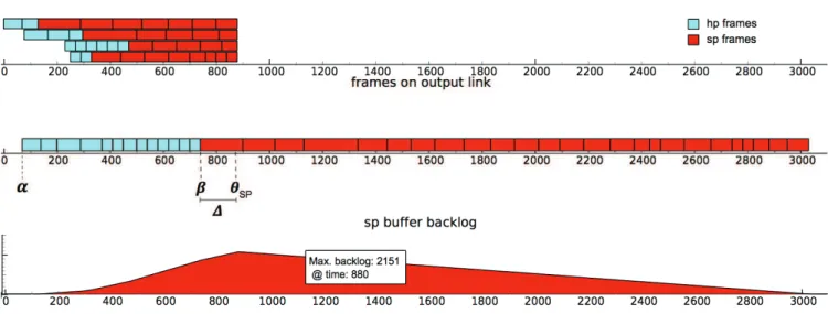
Figure 1 presents the arrival of sp and hp frames and how they are scheduled at the output port according to the fixed priority FIFO policy. Figure 1 further shows the backlog of the buffer under analysis (BufferS). In this figure, frames arrive
from four input links and compete for the same output port. Red frames have the same priority as the buffer under analysis (elements of VLS set) and blue frames are those with higher priority (elements of VLL set). The impact of lower priority
frames will be considered later.
Next we present the meaning of the points in time and time lengths depicted in the figure:
• α: start of transmission of hp frames • β: end of transmission of hp frames • θsp: end of reception of sp frames • ∆: θsp− β
For the sake of simplicity and without loss generality, we assume that s(f ) units of time is the amount of time required to send a frame of length s(f ).
The worst case backlog faced by BufferSoccurs after all sp frames arrive and the access of sp frames to the output port suffers the largest delay. Therefore, we compute blSmax at θsp
and construct a scenario in which all frames from VLH and
VLL delay the dispatch of sp frames the longest.
According to Figure 1, the computation of the worst case backlog for BufferScan be presented as the sum of all frames in VLS minus the amount of data transmitted during the time
interval∆, i.e.: blSmax= X ∀fS k∈VLS s(fS k)− | ∆ | (2)
An intuitive approach to construct a scenario that leads to the worst case backlog of BufferS, based on previous analysis
for single priority AFDX, is to assume that all hp frames arrive before the sp frames (see Figure 1). Further, frames arrive in decreasing order of size within the same set to avoid idle times at the output link [5].
According to equation (2), in order to achieve the worst case backlog for BufferS, the arrival sequence of the frames
should be such that| ∆ | is minimum. Intuitively, in order to compute the shortest∆ (which is equivalent to the longest β since θsp is constant), we should compute the latest α (αmax)
and assume that the output link will be busy with all hp frames until β, i.e.: β= αmax+ X ∀fH k∈VLH s(fkH) (3)
as depicted in Figure 1. In this example α= 70, P
∀fH k∈VLH
s(fH
k ) = 671 and therefore β = 741.
However, neither the scenario presented in Figure1 nor the equation (3) leads to the largest β for every set of frames.
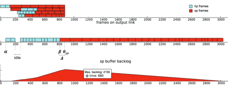
Figure 2 presents a scenario in which one frame of VLS
is shorter than in Figure 1. In this case, the set VLH remains
unchanged and so does the result of equation (3). Nevertheless, in Figure 2, β is larger than 741, in fact β= 771 due to an idle time of 30 units of time at the output link.
Figure 3 presents a scenario with the same frames as in Figure 2, but a different arriving sequence for the second input link: one lp frame arrives before the sequence of sp frames. Again, the result of equation (3) is 741 but the actual β is equal to 812, even larger than the one of the scenario presented in Figure 2 because of the larger idle time at the output link.
We can conclude that, although the frames arrive in de-creasing order of lengths per set (VLS, VLH, VLL), they do
not arrive in decreasing order of lengths if we consider all sets together. Therefore some idle time may be present at the output link and consequently equation (3) does not hold. We propose equation (4) to account for this idle time:
βmax= αmax+
X
∀fH k∈VLH
Fig. 1: Intuitive approach for the worst case scenario and computation of the worst case backlog for BufferS.
Fig. 2: Small change on previous scenario (one shorter sp frame) leads to idle time at the output link and β larger than the one computed by equation (3).
According to equation (4), we must achieve two goals in order to compute βmax:
1) compute the maximum idle time at the output link due to the non-decreasing arrival order of frames idlemax.
2) compute the latest point in time in which the set of hp frames start transmission (αmax) such that no sp frame
is transmitted before αmax.
Additionally, we must take into account the impact of lower priority frames.
IV. CONCLUSION AND FUTURE WORK
In this paper we presented the problem statement and the challenges for the computation of an upper bound for the backlog of each priority buffer on each output port of each switch of an extended AFDX network with n-priority levels (instead of two).
The challenges to compute an upper bound for the worst case backlog of each buffer, within the limits presented in (1), is summarized as follows:
• prove that equation (4) holds for any sequence of arriving
frames
• compute αmax • compute idlemax
• compute the impact of lp frames into the worst case
backlog of BufferS
Obviously, the computation of an upper bound for the worst case backlog of output buffers for the current AFDX network (with two priorities) is a sub problem of the one presented in this paper and can, therefore, be achieved by assuming n= 2.
Fig. 3: One sp frame arrives first on the second input link leading to larger idle time at the output link and thus larger values of β.
REFERENCES
[1] “ARINC specification 664 P7-1. Aircraft Data Network Part-7 Avionics Full-Duplex Switched Ethernet Network,” September 2009.
[2] F. Ridouard, J.-L. Scharbarg, and C. Fraboul, “Stochastic network calculus for buffer overflow evaluation in an avionics switched ethernet,” in Junior Researcher Workshop on Real-Time Computing, March 2007, pp. 55–58. [3] H. Bauer, J.-L. Scharbarg, and C. Fraboul, “Worst-case backlog evaluation of avionics switched ethernet networks with the trajectory approach,” in ECRTS, July 2012, pp. 78 –87.
[4] H. Bauer, J. Scharbarg, and C. Fraboul, “Applying and optimizing trajec-tory approach for performance evaluation of AFDX avionics network,” in ETFA, 2009, pp. 1–8.
[5] H. Bauer, J.-L. Scharbarg, and C. Fraboul, “Applying trajectory approach with static priority queueing for improving the use of available AFDX resources,” Real-Time Systems, vol. 48, no. 1, pp. 101–133, January 2012. [6] N. R. Garikiparthi, R. F. Coelho, and G. Fohler, “Calculation of worst case backlog for afdx buffers with two priority levels using trajectory approach,” in 12th Workshop on Real-time Networks (RTN13) in conjuc-tion with 25th Euromicro Internaconjuc-tional Conference on Real-time Systems (ECRTS13), July 2013.