Open Archive Toulouse Archive Ouverte (OATAO)
OATAO is an open access repository that collects the work of Toulouse researchers
and makes it freely available over the web where possible.
This is an author-deposited version published in:
http://oatao.univ-toulouse.fr/
Eprints ID : 3289
To cite this version : MICHON, Guilhem, ALMAJID, Ahmad, FERRERO,
Jean-François, ARIDON, Gwenaelle, FASCIO, Valia, HEURTEAU, Jean-Pierre. Dissipation
mechanisms identification of soft hollow particle-dampers in honeycomb structures for
micro-vibrations environment. In : 11 th European Conference on Spacecraft Structures,
Materials & Mechanical Testing (ECSSMMT), 15–17 September 2009, Toulouse, 6 p.
Any correspondence concerning this service should be sent to the repository administrator:
DISSIPATION MECHANISMS IDENTIFICATION
OF SOFT HOLLOW PARTICLE-DAMPERS
IN HONEYCOMB STRUCTURES FOR MICRO-VIBRATIONS ENVIRONMENT.
G. Michon1, A. Almajid2, J.F. Ferrero2, G. Aridon3, V. Fascio4, J.P. Heurteau5
1 Corresponding author
Université de Toulouse, ISAE, DMSM, 10 avenue Edouard Belin, 31 055 Toulouse, France
+33 (0)5 61 33 81 58
2 Université de Toulouse, UPS, LGMT, EA814,
118 route de Narbonne, 31 077 Toulouse, France
3 EADS – ASTRIUM
31 rue des cosmonautes, 31 402 Toulouse, France
4ATECA
Verlhaguet, 82 000 Montauban, France
5 BTS Industrie
Rue Jean Bart, 31 674 Labège, France
ABSTRACT
Particle dampers are enclosures partially filled with metallic or glass small spheres, attached to the vibrating structure. This paper deals with replacing hard classical particles by soft hollow ones to maximize damping and mass ratio. Hence, one aspect of this damping method is obtained by mixing the kinetic energy conversion of the structure into heat (frictional losses and collisions) and the elastic energy conversion into heat (visco-elastic deformation). This study is oriented toward experimental and theoretical investigations in order to distinguish the dissipation phenomena. The experimental approach first relies on identification and, then, on validation applied on composite aluminum honeycomb plates. Indeed, equivalent viscous damping is identified on small honeycomb samples; then cantilever honeycomb beams are filled with particles and studied. Theoretically, beyond the nonlinear dissipation by impact and friction, these particles add a visco-elastic behavior. The shapes of the hysteretic loops highlight that this behavior is predominant. Hence, oscillators are added in the FE model and permit to consider the effect of the particles. These kinds of particle dampers are highly nonlinear as a function of excitation frequency and amplitudes. The aim of this study is to provide a structural damping solution for space applications which require high pointing stability to enhance mission performances. In this perspective, damping of micro-vibrations was thought as a possible application; nevertheless it is shown that best efficiency is achieved in high frequency range.
1. INTRODUCTION
Particle dampers are enclosures partially filled with metallic or glass small spheres, attached to the vibrating structure. Mechanical energy is dissipated by non-elastic impact and friction between particles and walls. Unlike traditional damping technologies, particle dampers can provide damping in any direction and over a wide frequency range, thus attenuating several modes with one damper design. This method has a great potential to design passive control of structures with low influence on stiffness. Many papers were devoted to this subject [1-9].
The proposed paper deals with replacing hard classical particles by soft hollow ones to maximize damping ratio and to minimize the mass impact.. Hence, one aspect of this method is obtained by mixing the kinetic energy conversion of the structure into heat (frictional losses and collisions) and elastic energy conversion into heat (visco-elastic deformation).
This study is oriented toward experimental and theoretical investigations applied on composite aluminum honeycomb plates. The aim is to provide a structural damping solution for space applications which require high pointing stability to enhance mission performances..
The experimental approach relies on cantilever honeycomb beams, from which a polynomial curve-fitting modal analysis permits to extract damping loss
factors at the resonances. Damping effectiveness is found to be closely related to many parameters such as response amplitude and deformation (link to excitation level, boundary loading, natural frequencies and modes), particle type (material, density, diameter and roughness), particle size and filling rate (i.e. volume fraction).
The experimental approach first relies on identification and, then, on validation applied on composite aluminum honeycomb plates.. After experimental
observations, equivalent viscous damping is identified on small honeycomb samples. Then cantilever honeycomb beams are filled with particles and studied. Theoretically, beyond the nonlinear dissipation by impact and friction, these particles add a visco-elastic behavior. The shapes of the hysteretic loops highlight
that this behavior is predominant. Hence, oscillators
are added in the FE model and permit to consider the effect of the particles. This kind of particle dampers is highly nonlinear as a function of excitation frequency and amplitudes.
2. DAMPING IDENTIFICATION 2.1. First experimental observations
The first experimental set-up is dedicated to the observation of the particles granular behavior. It is composed of a box partially filled with the particles produced by ATECA, see Figure 1. This box, embedded on a 100N electrodynamic shaker, is subjected to a harmonic motion of frequency Ω and
acceleration amplitude γ.
Figure 1: First experimental set-up. Transparent box filled of particles, embedded on a
electrodynamic shaker
For a given frequency Ω= 22 Hz, it can be observed
different behaviors of the particle flow depending on the acceleration amplitude:
• Particles have a fluid behavior,
• The free surface takes an angle with the
horizontal axis,
• Particles have a global behavior, as if they were solid,
• Particles fill the whole cavity.
Then, honeycomb cells are added in the box in order to see the influence of the particles behavior, see Figure 2. This second configuration is subjected to harmonic motion. The previous specific frequency (Ω= 22 Hz)
has no more influence. Furthermore, it can be observed that even for large acceleration amplitudes (50 m/s²), particles remains in the bottom of each cell, at any frequency from 100 to 1000 Hz. For higher amplitudes, a few particles are separated from the group at the bottom of the cell. The granular behavior is no more observed.
Nevertheless, accurate measurements can’t be achieved due to the weight of the box which creates large inertial forces. Therefore, particles effect on the response is hidden into sensors noise. A more accurate experimental set-up will be necessary.
Figure 2: Box filled with particles in honeycomb cells.
2.2. Damping identification
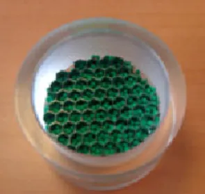
In order to perform reliable measurements, particle weight should be comparable to the cavity weight. Particles are therefore included in 40*40 mm honeycomb cells squares, see Figure 3.
Four filling ratios are compared: 0, 50, 80 and 100%. The 0% one is used as reference. These squares are embedded on a 10N electrodynamic shaker. A piezoelectric load cell is located between the cell and the shaker to measure the transmitted force, and a piezoelectric accelerometer measures the response on this system. It is check that no resonance occurs in the 10-3000 Hz frequency range by measuring frequency response functions. Then, different fixed harmonic excitations from 100 Hz to 1000 Hz are tested; for each frequency, five different amplitudes are applied on the system.
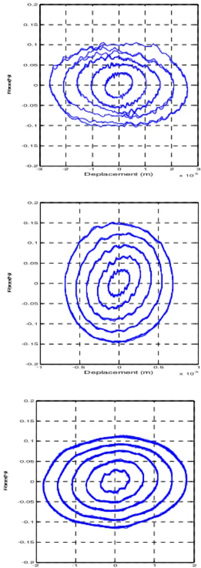
Figure 3: Second experimental set-up. Measurement post-processing permits to subtract inertia effects and to plot hysteretic loops in the displacement versus restoring force domain. Figure 4 presents these results for three excitation frequencies and five excitation amplitudes. These plots highlight very clearly a viscous damping behavior, as demonstrated by the elliptical shapes of the loops.
-3 -2 -1 0 1 2 3 x 10⁻⁵ -0.2 -0.15 -0.1 -0.05 0 0.05 0.1 0.15 0.2 Deplacement (m) F or ce (N ) -1 -0.5 0 0.5 1 x 10⁻⁵ -0.2 -0.15 -0.1 -0.05 0 0.05 0.1 0.15 0.2 Deplacement (m) F or ce (N ) -2 -1 0 1 2 x 10⁻⁶ -0.2 -0.15 -0.1 -0.05 0 0.05 0.1 0.15 0.2 Deplacement (m) F or ce (N )
Figure 4: Force-Deflection loops for three excitation frequencies and five excitation amplitudes.
As the viscous behavior is the predominant dissipation mechanism (higher that impact and friction losses), equivalent viscous damping is directly linked to the dissipated energy, i.e. to the area of the loops. Thus, it is extracted from this set of loops through the following relation, see Figure 5:
max max 2 2
2
dissipated eqW
F X
F
C
X
X
X
f
π
πω
πω
π
=
=
=
Displacement Force Fmax XFigure 5: Equivalent viscous damping identification From the previous tests, the equivalent viscous damping is identified as a function of the frequency f, displacement d and filling ratio r. Parameter values of
α, β, χ and δ are not given here.
(
)
( r d)eq
C
=
f d
α β
+
r e
− +χ δFrom this expression, influence of the frequency and amplitude are presented on Figure 6 and 7 respectively. It has to be noted that damping is linear with respect to the excitation frequency, and is representative of classical viscous mechanisms for the influence of the excitation amplitude. 0 100 200 300 400 500 600 700 800 900 1000 0 0.1 0.2 0.3 0.4 0.5 0.6 0.7 0.8 Frequence (Hz) Ceq (N /m /s )
Figure 6: Equivalent viscous damping versus excitation frequency for three filling rates for a
given amplitude (blue: 50%, pink: 80%, red: 100%).
0 1 2 3 4 5 6 x 10⁻⁴ 0 5 10 15 Displacement (m) Ceq (N /m /s )
Figure 7: Equivalent viscous damping versus excitation amplitude for three filling rates for a
given frequency (blue: 50%, pink: 80%, red: 100%).
3. INTRODUCING IN A CONTINUOUS DYNAMIC SYSTEM
3.1. Experimental set-up
The particles are introduced in a continuous dynamic system. This system is a cantilever honeycomb beam, excited at its free end by a 10N electrodynamic shaker, see Figure 8. A force sensor and four accelerometers are used to measure the excitation and the response of the beam respectively.
Figure 8: Cantilever beam experimental set-up 3.2. Results
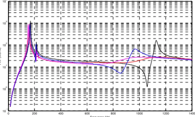
Step sine excitation tests from 10 to 1500 Hz are carried out. Frequency response functions are presented on Figure 9 for different particle filling ratio (0%, 50%, 80% and 100%). The first bending natural frequency is located in the vicinity of 190 Hz, as the second bending natural frequency is comprised between 900Hz and 1100Hz. The pick located at 210 Hz corresponds to the torsion mode. This study will focus only on the bending modes as the damping as been identified in one direction. 0 200 400 600 800 1000 1200 1400 10-1 100 101 102 103 104 Frequence (Hz) FR F (m /s ²/N )
Figure 9: Experimental FRF for four filling rates (black: 0%, blue: 50%, pink: 80%, red: 100%). The following table presents the natural frequency and damping ratios identified by curve fitting on the FRF for each type of beam.
First bending
mode Second bending mode
Beam Filling ratio
(%) frequency Natural (Hz) Damping Ratio (%) Natural frequency (Hz) Damping Ratio (%) Refer ence 0 160 0.5 1038 0.9 1 100 155 1.0 1016 7.4 2 80 153 0.5 916 13.8 3 50 160 0.5 918 2.5
It can be observed from the previous results that the first mode is not damped while for the second one, the particles have a real influence, especially for a filling ratio of 80%.
4. COMPARISON WITH FINITE ELEMENTS RESULTS
4.1. Model
The FE reference model is composed of a clamped-free beam modeled by 14 beam elements, see Figure 10. This model permits to verify the mechanical characteristics of the honeycomb structure.
Figure 10: Reference model of a cantilever beam. Following the previous investigations, particles dissipate energy through viscous damping process. This damping is introduced on an oscillator, where m is the mass of the particles, and C is Ceq. Theses oscillators have no stiffness, see Figure 11. Damping values, identified on 40x40mm samples, are defined by unit of surface area. Due to the size of the beam compared to the size of the sample used in section 2.2,
a set of five oscillators are used to cover the filling zone of the honeycomb beam. Harmonic finite element calculations are computed for an excitation force
F=F0.cos(Ωt).
F0 cos(ΩΩΩt) Ω
Figure 11: Representation of the FE model of the cantilever beam filled with particles. 4.2. Results
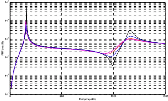
Predicted frequency response functions are plotted Figure 12. These responses highlight the same behaviors as the experimental results, mostly for damping ratios. No natural frequency shift is predicted by the proposed FE model while it has been observed experimentally. It is certainly due to the cutting of the beam which can’t be accurate because of the honeycomb. Moreover, the mass of the oscillators are kept constant in the model, whereas particle mass varies in the real system.
0 500 1000 1500 10-1 100 101 102 103 104 Frequency (Hz) F R F (m /s ²/N )
Figure 12: FRF predicted for four filling rates (black : 0%, blue : 50%, pink : 80%, red :100%). The following table presents the natural frequency and damping ratios identified by bandwidth method on all types of beam.
First mode Second mode
Beam Filling ratio (%) Natural frequency (Hz) Damping Ratio (%) Natural frequency (Hz) Damping Ratio (%) Refer ence 0 160 0.3 1162 2.2 1 100 154 1.5 1165 9.0 2 80 154 1.0 1159 10.6 3 50 155 1.0 1168 4.1
Damping efficiency provided by the soft hollow spheres can be predicted in a continuous system by the proposed FE model.
Therefore, this model might be used in more complex structures and to optimize the filling zone of the particles in honeycomb structures.
5. CONCLUSION AND PERSPECTIVES
The objective of the presented work was to develop a methodology to model the behavior of soft hollow spheres embedded in an aluminum honeycomb. This study permits to highlight the following conclusions:
• Dissipation mechanism is identified as viscous
damping due to the elliptical shape of the hysteretic loops
• Impact or friction dissipation mechanisms are
not predominant.
• This kind of particle dampers present good performances at high frequency
The perspectives are oriented towards the optimization of the particles location and the use of the numerical model to predict the behavior of complex structures.
Acknowledgements: These results benefit from Midi-Pyrenées Region and CNES fundings.
6. REFERENCES
1. C. Saluena, T. Poschel, and S. E. Esipov,
Dissipative properties of vibrated granular materials, Physical Review (1999), 59(4), pp 4422-4425.
2. C. Cempel and G. Lotz, Efficiency of vibrational energy dissipation by moving shot, Journal of
Structural Engineering (1993), 119(9), pp
2624-2652.
3. R. D. Friend and V. K. Kinra, Particle impact damping, Journal of Sound and Vibration (2000), 233(1), pp 93-118.
4. S. S. Simonian. Particle Damping Applications.
45th AIAA/ASME/ASCE/AHS/ASC Structures, Structural Dynamics & Materials Conference,
April 2004, Palm Springs, California.
5. Y. Yang "Development of master design for particle impact dampers, PhD thesis, The Pennsylvania State University, 2003
6. M. Saeki, Analytical study of multi-particle
damping, Journal of Sound and Vibration (2005), 281, pp 1133–1144.
7. W. Liu, G.R. Tomlinson and J.A. Rongong, The dynamic characterization of disk geometry particle dampers, Journal of Sound and Vibration (2004), 280, pp 849-861.
8. S. Ramachandran and G. Lesieutre, Dynamics and
performance of a harmonically excited vertical impact damper, Journal of Vibration and
Acoustics (2008), 130.
9. Z. Xu, M.Y. Wang and T. Chen, An experimental
study of particle damping for beams and plates,
Journal of Vibration and Acoustics (2004), 126, pp