This is an author-deposited version published in:
http://oatao.univ-toulouse.fr/
Eprints ID: 4480
To cite this document:
TRAN-THAI Tuan, LOPEZ-PACHECO Dino Martin,
LOCHIN Emmanuel, ARNAL Fabrice. Towards an incremental deployment of ERN
protocols: a proposal for an E2E-ERN hybrid protocol. In: PFLDNet, 28-29 Nov
2010, Lancaster, USA.
Any correspondence concerning this service should be sent to the repository
administrator:
[email protected]
Towards an incremental deployment of ERN protocols: a
proposal for an E2E-ERN hybrid protocol
Dino Lopez Pacheco
University of Nice I3S / CNRS UMR 6070 Sophia-Antipolis, France
[email protected]
Tuan Tran Thai
University of Toulouse TeSA Toulouse, France
[email protected]
Emmanuel Lochin
University of Toulouse ISAE; CNRS; LAAS Toulouse, France[email protected]
Fabrice Arnal
Thales Alenia Space Toulouse, France
fabrice.arnal
@thalesaleniaspace.com
ABSTRACT
We propose an architecture based on a hybrid E2E-ERN approach to allow incremental deployment of ERN (Explicit Rate Notification) protocols in heterogeneous networks. The proposed IP-ERN architecture combines E2E (End-to-End) and ERN protocols and uses the minimum between both congestion windows to perform. Without introducing com-plex operation, the resulting E2E-ERN protocol provides inter and intra protocol fairness and benefits from all ERN protocol advantages when possible. We detail the principle of this novel IP-ERN architecture and show that this ar-chitecture is highly adaptive to the network dynamic and is compliant with IPv4, IPv6 as well as IP-in-IP tunneling solutions.
Keywords
Explicit Rate Notification, E2E, TCP, XCP, Gradual de-ployment
1.
INTRODUCTION
TCP New Reno (denoted standard TCP in the rest of the paper) was the dominant protocol in charge of providing con-gestion control, fair share and full utilization of the network resources. Standard TCP provides good performance in terms of link utilization in networks with short propagation delay (only a few ten of milliseconds) and low bandwidth (less than 100Mb/s). However, this TCP variant is known to obtain poor performance in large bandwidth×delay prod-uct (LBDP) networks.
Following the pervasive deployment of gibabit links, large bandwidth×delay product (LBDP) networks are now com-mon in the Internet. To solve the problem of standard TCP
Permission to make digital or hard copies of all or part of this work for personal or classroom use is granted without fee provided that copies are not made or distributed for profit or commercial advantage and that copies bear this notice and the full citation on the first page. To copy otherwise, to republish, to post on servers or to redistribute to lists, requires prior specific permission and/or a fee.
PFLDNet2010 Lancaster, Pennsylvania, USA
Copyright 20XX ACM X-XXXXX-XX-X/XX/XX ...$10.00.
over LBDP networks, high speed variants have been pro-posed such as CUBIC [1] (currently enabled by default in GNU/Linux systems), Compound TCP (deployed in recent Windows systems) [2] and High Speed TCP [3] (available over *BSD systems). However, it has been shown in [4, 5] that these TCP variants potentially lead to congestion states and intra/inter-protocol unfairness. The intra-protocol and inter-protocol fairness indicate, respectively, the fairness be-tween flows using either the same or different protocols.
Others high speed TCP variants, known as delay-based protocols such as FAST TCP [6], consider an increase of the round-trip time (RTT) as a congestion indicator. Thus, they monitor the RTT at the sender side to prevent congestion state. However, delay-based protocols do not solve the prob-lem of intra/inter-fairness [5]. High speed TCP variants and delay-based protocols belong to the end-to-end (E2E) proto-cols class since they control the congestion on an end-to-end basis.
A potential transport protocol solution to LBDP networks would be the use of an Explicit Rate Notification (ERN) pro-tocol where routers inform the sender of the optimal send-ing rate (for instance the eXplicit Control Protocol - XCP [7]). This kind of protocols demonstrates high performance and intra-protocol fairness in full ERN-capable networks [7] (i.e. where all routers support ERN capabilities). The major problem to the deployment of such concept is that ERN pro-tocols do not implement any mechanisms to deal with net-works where non-ERN protocols (e.g., standard TCP) and non-ERN equipments (e.g., DropTail routers) are present. Indeed, it has been proved that ERN protocols in non-full ERN networks perform worse than every TCP variants [8, 9]. Therefore, ERN protocols cannot be used in heteroge-neous networks and can not be gradually deployed in the current Internet.
Despite several important efforts to enable an incremental deployment of ERN protocols in heterogeneous networks, we will see in Section 2 that the proposed solutions do not (or only partially) solve the problems related to the interaction between ERN protocols with ERN protocols and non-ERN devices.
In this paper, we propose a novel architecture allowing to perform an incremental deployment of ERN protocols over heterogeneous networks. In this architecture, a sender is
able to adapt its emitting rate as a function of a DropTail or an ERN-capable bottleneck. This operation is done dy-namically, meaning that when the sender receives an ERN feedback, it uses the minimum between the ERN and E2E congestion windows to perform. After showing the strengths and weaknesses of current existing solutions, we detail the IP-ERN architecture in Section 3. We also explain why our solution is compatible with most of TCP variants; most of proposed ERN protocols; with IPv4, IPv6 and IP-in-IP tun-neling mechanisms. Additionally, Section 4 shows the ben-efits of the proposed architecture and the scenarios where such benefits are possible. Later, we present simulations in order to validate our IP-ERN architecture (Section 5) and conclude this article with a list of some remaining issues and expected future work (Section 6).
2.
RELATED WORK
To provide TCP-friendliness (i.e. inter-protocol fairness), the authors in [9] proposed to probabilistically estimate the number of ERN and non-ERN flows (by the mean of a zom-bie list as described in [10]) to determine if non-ERN flows use more bandwidth than ERN ones. If so, an amount of non-ERN packets are probabilistically dropped. Later in [11], the authors improved this strategy and added an al-gorithm to calculate the aggressiveness of non-ERN flows (how much bandwidth obtain non-ERN flows over a period of time).
However, one weakness of the zombie estimator is its ac-curacy. For instance, flows with a short congestion window might not always be detected. Additionally, each router
needs a period of estimation (denoted test) to correctly
per-form and the estimated value will only be applied in the
next test period. As a result, the needed time to modify
the behavior of the sender is roughly 2 ∗ test+ RT T in the
best case. While in isolated networks, the number of flows might remain stable for a long period of time. We believe further analysis is needed before extending this hypothesis to the Internet. This problem of latency between the esti-mation and its use applies to the aggressiveness estiesti-mation proposed in [11]. Furthermore, heterogeneous RTTs might lead to a sensible difference between the computed aggres-siveness and the aggresaggres-siveness of the flow with the largest RTT.
Concerning the cohabitation between ERN flows and non-ERN equipments, [11] proposed a heuristic to detect bot-tlenecks with non ERN capabilities and switch up to TCP when this case occurs. With this heuristic, if the current RTT reaches twice the base RTT, or the receiving rate does not match the ERN predicted rate, then the bottleneck is non-ERN capable. However, further analysis is needed to assess whether the RTT would reach the threshold before experiencing losses due to congestion in non-ERN routers. Defining upper and lower bounds to compare both the re-ceived and the predicted rate is not trivial, thus, this heuris-tic might frequently return false-positive results. At last but not least, there is no way to detect when the bottleneck has moved to an ERN router again. Following the dynamic char-acter of the Internet, the sender might not correctly take advantage of ERN capabilities when possible.
3.
PRESENTATION OF THE IP-ERN
ARCHI-TECTURE
3.1
Rationale of IP-ERN architecture
TCP-based protocols frequently probe the network capac-ity by increasing their emitting rate, hence leading to con-gestion events. Additionally, high speed TCP variants po-tentially increase the unfairness. While delay-based proto-cols attempt to prevent congestion states, they also prevent under-utilization of bandwidth by keeping a certain number of packets in the buffer of the bottleneck. Unfortunately, delay-based protocols do not solve the problems of unfair-ness [5]. On the contrary, thanks to the assistance provided by routers, ERN protocols provide both high link usage and intra-fairness while minimizing the buffer occupancy.
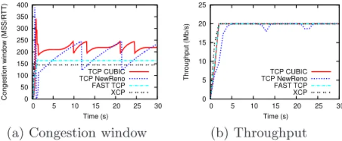
Figure 1 presents the general behavior of one ERN pro-tocol (XCP) and different E2E propro-tocols (TCP New Reno, CUBIC, FAST TCP) over a short BDP network (the bot-tleneck is 20Mb/s and the RTT is 30ms). The results are
obtained with the ns-2 simulator [12]. The router queue
is XCP in case of XCP and DropTail for other cases. In Figure 1(b), all protocols achieve the bottleneck capacity. Specifically, XCP uses the smallest congestion window (Fig-ure 1(a)). This means that XCP maximizes the link utiliza-tion while minimizing the buffer occupancy. Indeed, when the TCP New Reno’s congestion window is smaller than the XCP’s congestion window, TCP New Reno’s through-put is slightly lower than 20Mb/s. Moreover, when the XCP sender receives misleading congestion window in non-fully XCP-capable network, XCP’s congestion window might per-form worse than E2E protocols [8].
0 50 100 150 200 250 300 350 400 0 5 10 15 20 25 30 Congestion window (MSS/RTT) Time (s) TCP CUBIC TCP NewReno FAST TCP XCP
(a) Congestion window
0 5 10 15 20 25 0 5 10 15 20 25 30 Throughput (Mb/s) Time (s) TCP CUBIC TCP NewReno FAST TCP XCP (b) Throughput Figure 1: Comparison between E2E and ERN pro-tocols
When the bottleneck is ERN-capable, ERN protocols can compute the optimal congestion window. However, when the bottleneck is not ERN capable, E2E protocols provide a more adaptive congestion window. Following this, the idea is to combine E2E and ERN protocols and to use the min-imum between the E2E’s and the ERN’s rates in order to be compliant with current protocols (i.e., no more aggres-sive than TCP) while using the optimal congestion window when it is applicable.
3.2
Proposed IP-ERN architecture
Combining E2E and ERN protocols implies the implemen-tation of two different congestion control protocols in the sender node. Since ERN protocols do not introduce com-plex operations at the sender side, we believe that current computers should have enough resources to run both E2E and ERN protocols.
The proposed architecture (denoted IP-ERN architecture in the following) requires only slight modifications at the end hosts and few additional mechanisms inside the routers. Our
architecture does not need either heuristic or probabilistic methods to enable a gradual deployment of ERN protocols over current heterogeneous networks.
3.2.1
At the source side
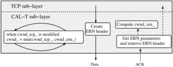
The Transport Layer is divided into two sub-layers: the TCP sub-layer and the Congestion Awareness sub-layer at the Transport Level (CAL-T). The TCP sub-layer hosts the core of the TCP-based congestion control protocol. The CAL-T hosts the core of the ERN protocol and all needed mechanisms to properly combine both E2E and ERN capa-bilities.
When a SYN packet is sent to establish a connection, the CAL-T layer inserts a TCP option field to indicate an E2E-ERN capable sender1. Later, at the reception of a SYN-ACK, the sender checks inside the packet a TCP option indicating that the receiver is E2E-ERN capable. If so, the E2E-ERN connection is established. Otherwise, a standard E2E connection is created.
After establishing a connection with an E2E-ERN capable receiver, CAL-T adds to every outgoing packets the ERN parameters that need to be sent to the ERN routers (i.e. the ERN “header”). The sender’s desired feedback will be placed in a field called drd feedback, which is the only field that a router can modify. In IPv4 networks, CAL-T puts the ERN parameters between the IP header and the TCP header (as suggested in [14]). This should allow routers to quickly find the ERN parameters. Note that (i) placing the ERN parameters in the TCP option field might require expensive operation at routers, and (ii) placing it in the IP option field would cause IP-ERN packets to be kicked out into the slow path [15]. For IPv6 networks, we propose to create a new Extension Header (EH) which belongs to the upper-layer group to carry up the ERN parameters. Then, CAL-T places such an EH according to the IPv6 principles. Therefore, non-ERN capable routers should simply forward this packet avoiding without slow path redirectionare
CAL−T sub−layer Data ACK when cwnd_tcp_ is modified cwnd_ = min(cwnd_tcp_, cwnd_ern_) Create ERN header Compute cwnd_ern_ Get ERN parameters and remove ERN header
TCP sub−layer
Figure 2: Source node
Concerning incoming packets, upon reception of an ACK, CAL-T extracts the ERN feedback to compute the ERN con-gestion window (cwnd ern ). Such a feedback will be taken from a field called reverse feedback and will never be modi-fied by IP-ERN routers. Finally, CAL-T takes the minimum value according to (1):
cwnd= min{cwnd tcp , cwnd ern } (1) where cwnd tcp is the last updated TCP congestion win-dow. As we will see later, by taking the minimum value be-1Note that non E2E-ERN capable receivers should only ig-nore this option and following [13], a majority of TCP stacks correctly handle unknown TCP option (i.e. packets that contain unknown options are not dropped).
tween cwnd tcp and cwnd ern , this architecture does not require any explicit mechanism to detect whether there is a non ERN-capable router in the networks. In other words, the detection is automatically done by this comparison. Ad-ditionally, the time needed to switch from E2E to ERN ca-pabilities (or reverse) is not longer than one RTT (time to detect a loss when going from ERN to E2E or time to receive the signaling from routers when going from E2E to ERN). Figure 2 presents this new architecture at the sender side.
We want to point out that this architecture is compati-ble with any TCP variants and with most of existing ERN protocols.
3.2.2
At the router side
All needed ERN algorithms are placed in the Congestion Awareness sub-Layer at the Network Level (CAL-N), as de-picted in Figure 4.
When a packet arrives at an ERN-capable router, CAL-N checks if the next protocol (or next header in IPv6) signaled in the IP header of the incoming packet belongs to an E2E-ERN sender. If so, the router computes the feedback and updates the drd feedback field from the ERN header accord-ing to the ERN rules. Otherwise, packets are treated as default IP packets.
Since ERN-capable routers only assign bandwidth to ERN flows (as E2E flows do not interpret the feedback message), and because E2E and ERN fairness is enabled by the E2E capabilities of senders using our architecture, each router computes a feedback by taking into account the ERN traffic only. Most ERN protocols need to compute the input traffic rate. Therefore, input traffic rate corresponds to the ERN traffic only.
In IP-ERN routers, there is one main buffer (the shared buffer), serving two buffers (E2E and ERN buffers with
re-spectively fixed sizes X and Y) as depicted in Figure 3. E2E
buffer only stores packets from E2E flows and ERN buffer only stores packets from IP-ERN flows. The packets from the shared buffer are immediately forwarded to the next buffer. If this buffer is full, packets are simply dropped. This buffer schemeeases the feedback computation without
taking into account pure E2E traffic. Indeed, ERN protocols
usually need to estimate the buffer occupancy of ERN flows to decrease their rate and to drain packets in order to pre-vent congestion. Calculating the buffer occupancy without differentiation between ERN and E2E traffic might decrease
IP-ERN senders’ rate to drain E2E packets.
incoming packets x% y% E2E buffer ERN buffer Shared buffer (100−x−y)% packets outgoing
Figure 3: Egress buffer scheme for IP-ERN routers
Note that in this proposition, IP-ERN routers do not at-tempt to provide fairness (such as in [11, 9]). Inter and intra fairness are ensured by E2E and ERN capabilities of E2E-ERN senders.
3.2.3
At the destination side
same sub-layers than the sender side (i.e. TCP and CAL-T sub-layers). When a SYN is received, CAL-T looks at the TCP option field to know if the sender is E2E-ERN capable. If so, CAL-T sends back a SYN-ACK packet with a code in the TCP option field to indicate an E2E-ERN capable receiver.
During the connection, upon reception of a data packet, CAL-T copies the drd feedback field of the data packet to the reverse feedback field of the ACK, and sets drd feedback = 0. CAL-T builds the outgoing ACK in the same way the sender builds a data packet (described earlier). The next protocol type (or next header in IPv6) signaled in the IP header of ACKs will be the same as the one signaled in data packets.
3.2.4
Global view of the IP-ERN architecture
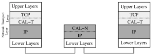
Figure 4 gives a general view of the proposed IP-ERN ar-chitecture. Note that the Transport Layer at end-hosts is divided in one TCP sub-layer (where the core of the TCP protocol is hosted) and one CAL-T sublayer (which hosts the core of the ERN protocol and handles the interaction between E2E and ERN protocols). The Network Layer in-side the routers is divided in one IP sub-layer (where the core of the IP protocol is hosted) and one CAL-N sub-layer (which hosts the core of the ERN congestion control proto-col). In the following, we show that this architecture enables E2E-ERN fairness and allows the use of E2E-ERN protocols over heterogeneous networks.
Network Layer Transport Layer IP CAL−N IP TCP IP TCP CAL−T CAL−T Upper Layers
Lower Layers Lower Layers Lower Layers Upper Layers
Figure 4: The proposed IP-ERN architecture.
3.2.5
The IP-ERN architecture in the context of IPsec
tunnels
The IP-ERN architecture is fully compatible with IPsec tunnels. Indeed, the encryption and/or authentication of the whole or partial IP datagram by legacy IPsec boxes makes IP-ERN senders to behave like a pure TCP sender. How-ever, in the future, a new generation of IPsec-ERN boxes can be implemented. Indeed, we are currently working on the proposition of the IPsec-ERN architecture, as well as turn around to benefit from ERN capabilities in presence of legacy SatIPsec [16] or legacy IPsec boxes1.
4.
BENEFITS OF THE PROPOSED IP-ERN
ARCHITECTURE
4.1
Possible gradual deployment scenarios
The IP-ERN architecture allows a gradual deployment of ERN protocols (such as XCP) over heterogeneous networks. Three scenarios are possible to drive this deployment: 1These propositions will be part of a document entirely fo-cused on the security protocols and IP-ERN architecture interactions
4.1.1
1stscenario: the bottleneck is IP-ERN capable
and only IP-ERN flows share the resources
Each host implementing the IP-ERN architecture should fully benefit from ERN capabilities. Although this scenario does not correspond to what we usually call an incremen-tal deployment (we consider here only IP-ERN flows), there are some cases where network administrators might consider this solution to improve the performance of large data trans-fer as we will see in Section 4.2.
4.1.2
2ndscenario: the bottleneck is not IP-ERN
ca-pable
IP-ERN hosts should not benefit from the ERN capabili-ties but they should fully benefit from TCP capabilicapabili-ties.
4.1.3
3rdscenario: the bottleneck is IP-ERN capable
and both TCP and IP-ERN flows share the link
IP-ERN hosts will use their TCP capabilities to compete against pure TCP flows. Furthermore, the intra-fairness level of E2E-ERN flows can be higher than the intra-fairness of pure E2E flows despite of the use of TCP capabilities. In-deed, IP-ERN routers try to equally share the link capacity between ERN-capable flows only. When a new E2E-ERN flow enters in the network, IP-ERN routers make E2E-ERN flows converge to a rate equal to the ratio between the link capacity and the number of IP-ERN flows. Therefore, old flows yield up bandwidth once new feedbacks are received, and the newest flow safely acquires the available resource, making convergence between E2E-ERN flows faster than pure E2E flows. In fact, as the throughput of E2E flows decreases, the intra-fairness property of the ERN protocol increases. Other simulation results not shown here due to the limited space confirm these arguments.
Finally, we want to remark that using the minimum be-tween TCP and ERN congestion windows, during the slow-start phase or after a packet loss, IP-ERNs flow are mainly limited by TCP protocol. However, because of the use of CUBIC in GNU/Linux distributions and Compound TCP in some Microsoft’s products, we believe that the under-usage of resources is not a problem anymore. The main one remains the unfairness introduced by Compound TCP and CUBIC. However, this unfairness can be reduced with the use of our IP-ERN architecture.
4.2
Scenarios of utilization
For instance, the use of the proposed IP-ERN architecture should greatly improve the performance of flows:
• in a Virtual Private Network (VPN) with frequent long-lived flows, assuming (i) we place an ERN router at the entry point; (ii) most of the time this is the bottleneck and (iii) most of senders implement the IP-ERN architecture;
• in a satellite scenario, assuming (i) we place an ERN capable router at the up-link and down-link and (ii) most of senders implement the IP-ERN architecture.
5.
RESULTS AND ANALYSIS
5.1
Topology
We use the Network Simulator ns-2 to evaluate our pro-posal. Unless something else is specified, next simulations
use a network topology with a base RTT of 300ms and a bottleneck capacity of 20Mbps (see Figure 5). The number of senders and receivers depend on the number of simulated flows.
100Mb/s 20Mb/s 100Mb/s
10ms 130ms 10ms
Figure 5: Simulation topology
5.2
Correctness of E2E-ERN protocols
In our implementation of the IP-ERN architecture, we used CUBIC TCP at the TCP sub-layer (since this is cur-rently enabled by default in Linux), and XCP at the CAL-T sublayer (which is implemented by default in ns-2 ). Follow-ing the network settFollow-ings described in Section 5.1, we perform two different simulations. We run a CUBIC-XCP flow when bottleneck router is XCP (first simulation) and DropTail (second simulation).
As stated in Section 4.1, E2E-ERN protocol behaves like ERN in the possible cases where the bottleneck router is ERN-capable and only ERN flows are present in the bottle-neck. Otherwise, E2E-ERN protocol uses their E2E capa-bility to better adapt its throughput. The results given in Figure 6 confirm this. Indeed, CUBIC-XCP behaves like a pure CUBIC TCP in case the bottleneck router is DropTail, and acts as XCP in case the bottleneck router is XCP.
0 200 400 600 800 1000 1200 1400 0 50 100 150 200 250 300
Congestion window (MSS/RTT) Time (s)
CUBIC-XCP / DropTail CUBIC-XCP / XCP
Figure 6: CUBIC-XCP in presence of DropTail or XCP routers
5.3
Intra-fairness
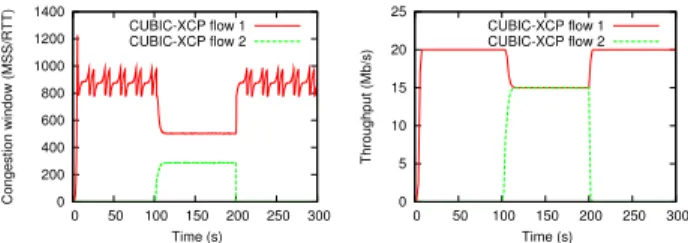
The intra fairness is a metric that corresponds to the fair-ness between flows using the same protocol. To analyze the intra-fairness capability of our IP-ERN architecture, we sim-ulated four CUBIC-XCP flows which share the same bottle-neck with XCP-capabilities. Four flows start and terminate at different times.
Figure 7 shows the congestion window evolution of XCP flows. When flows enter or leave the network, CUBIC-XCP quickly converges to the new equilibrium and remains stable. We remark again that in the presence of only E2E-ERN flows and when the bottleneck router is E2E-ERN-capable, the E2E-ERN protocol behaves like ERN protocol, which re-sults in excellent intra-fairness properties [7]. Even though it is not graphically shown, we have observed of full link usage.
We have also driven the same experiment with DropTail routers. The results have shown that CUBIC-XCP behaves like a pure CUBIC flow since the ERN part is not aware of
0 100 200 300 400 500 600 700 800 900 0 50 100 150 200 250 300
Congestion window (MSS/RTT) Time (s)
CUBIC-XCP flow 1 CUBIC-XCP flow 2 CUBIC-XCP flow 3 CUBIC-XCP flow 4
Figure 7: Intra-fairness between CUBIC-XCP flows
the bottleneck capacity (XCP assumes an infinite available bandwidth).
5.4
Inter-fairness
The inter fairness implies the fairness between flows using different protocols. In order to show the inter-fairness, we perform the following simulation: one CUBIC flow competes against two CUBIC-XCP flows and an XCP router is used at the bottleneck link (see Figure 5). We can see in Fig-ure 8 that our IP-ERN architectFig-ure allows CUBIC-XCP to use its E2E capacities in order to fairly share the available bandwidth with pure CUBIC flow. As shown in Figure 8 where one CUBIC-XCP flow competes against two CUBIC flows, having more pure CUBIC flows than CUBIC-XCP flows does not impact on the fairness.
Since in our IP-ERN architecture, ERN routers only see ERN traffic (see Subsection 3.2), routers attempt to assign bandwidth to ERN flows without taking into account the E2E traffic. Later, the E2E capabilities of E2E-ERN senders allow the flows to converge. Taking into account all the traffic to compute a feedback (as in the original XCP model) do not allow ERN senders to compete against E2E flows [9].
0 5 10 15 20 25 0 100 200 300 400 500 600 700 800 900 1000 Throughput (Mb/s) Time (s) One CUBIC TCP vs Two CUBIC-XCP
CUBIC TCP CUBIC-XCP flow 1 CUBIC-XCP flow 2 0 5 10 15 20 25 0 100 200 300 400 500 600 700 800 900 1000 Throughput (Mb/s) Time (s) Two CUBIC TCP vs One CUBIC-XCP
CUBIC-XCP CUBIC TCP flow 1 CUBIC TCP flow 2
Figure 8: Inter-fairness between CUBIC and CUBIC-XCP
Using our proposed IP-ERN architecture, convergence time between E2E and E2E-ERN protocols strongly depend on the kind of E2E protocol used for both.
5.5
Dynamic scenario
The following simulation show how fast and transparent is the adaptation of the senders using the IP-ERN architecture
in the context of a variable environment. The experiment is done over the topology depicted in Figure 9. The base RTT is 300ms for the flow #1 between Sender #1 and Receiver #1, and 180ms for flow #2 between Sender #2 and Receiver #2. Note that flow #1 is active between t = [0; 300] seconds and flow #2 between t = [100; 200]. Except Router #1 which uses DropTail, all other routers use XCP.
10ms 10ms Sender 1 Sender 2 Receiver 1 Receiver 2 20Mb/s 60ms
Router 1 Router 2 Router 3 Router 4
100Mb/s 10ms 30Mb/s 60ms 10ms 10ms 100Mb/s 100Mb/s 100Mb/s 100Mb/s
Figure 9: Network topology for dynamic scenario
In Figure 10, between t = [0; 100], flow #1 behaves like a pure CUBIC flow as the bottleneck queue is DropTail at Router #1. Later, when the bottleneck moves from Router #1 to Router #3 (Router #3 is ERN capable) due to the presence of flow #2, both flows behave like a pure XCP pro-tocol and both have a throughput of 15Mbps. The difference between each congestion window is caused by the RTTs dif-ference.This simulation shows that our E2E-ERN protocol automatically switches between E2E and ERN modes de-pending on network condition thanks to equation (1).
0 200 400 600 800 1000 1200 1400 0 50 100 150 200 250 300 Congestion window (MSS/RTT) Time (s) CUBIC-XCP flow 1 CUBIC-XCP flow 2 0 5 10 15 20 25 0 50 100 150 200 250 300 Throughput (Mb/s) Time (s) CUBIC-XCP flow 1 CUBIC-XCP flow 2
Figure 10: Dynamic scenario for CUBIC-XCP
6.
CONCLUSIONS AND FUTURE WORK
We propose a novel IP-ERN architecture which allows an incremental deployment of ERN protocols over heteroge-neous networks where a pure ERN architecture is not fully deployable yet. We also detail an implementation proposal based on the introduction of two sub-layers. This architec-ture is compliant with IPv4 and IPv6 networks and does not break the end-to-end communication thus allowing the use of protocol such as IPSec.
We have shown that the use of the proposed IP-ERN ar-chitecture allows the senders to benefit from both the ro-bustness of E2E protocols and high performance of ERN protocols according to the network conditions. The combi-nation of E2E and ERN capabilities is transparently man-aged by the IP-ERN architecture. The switching from E2E to ERN capabilities (or reverse) is done in no more than one RTT.
We now plan to develop a real prototype of this architec-ture to better assess its performance and to discuss other
aspects of this architecture (security issues, impact of mice flows) in a future contribution.
7.
REFERENCES
[1] Injong Rhee and Lisong Xu, “CUBIC: A New TCP-Friendly High-Speed TCP Variant,” in PFLDNet, February 2005.
[2] Kun Tan, Jingmin Song, Qian Zhang, and Murari Shridaran, “Compound TCP: An Scalable and TCP-Friendly Congestion Control for High-Speed Networks.,” in IEEE Infocom, April 2006. [3] S. Floyd, “HighSpeed TCP for Large Congestion
Windows,” RFC 3649 (Experimental), Dec. 2003. [4] Junsoo Lee al., “A study of TCP fairness in
high-speed networks,” Tech. Rep., University of California, Santa Barbara, apr 2005, Available at http://www.ece.ucsb.edu/~hespanha/published. [5] Sangtae Ha, Yusung Kim, Long Le, Injong Rhee, and
Lisong Xu, “A step toward realistic performance evaluation of high-speed TCP variants,” in Elsevier Computer Networks Journal, 2006.
[6] Cheng Jin, David X. Wei, and Steven H. Low, “FAST TCP: Motivation, Architecture, Algortihms,
Performance,” in IEEE Infocom, March 2004. [7] D. Katabi, M. Handley, and C. Rohrs, “Congestion
Control for High Bandwidth-Delay Product Networks,” in ACM Sigcomm, 2002.
[8] Dino Lopez Pacheco, Congduc Pham, and Laurent Lef`evre, “XCP-i : eXplicit Control Protocol for heterogeneous inter-networking of high-speed networks,” in IEEE Globecom, 2006.
[9] Dino Lopez Pacheco, Congduc Pham, and Laurent Lef`evre, “Fairness issues when transferring large volume of data on high speed networks with router-assisted transport protocols,” in High Speed Networks Workshop, in conjunction with IEEE Infocom, May 2007.
[10] T. J. Ott, T. V. Lakshman, and L. H. Wong, “SRED: Stabilized RED,” in IEEE Infocom, 1999.
[11] Chia-Hui Tai, Jiang Zhu, and N. Dukkipati, “Making large scale deployment of rcp practical for real networks,” in IEEE Infocom, April 2008. [12] “The Network Simulator
http://www.isi.edu/nsnam/ns/index.html,” . [13] Alberto Medina, Mark Allman, and Sally Floyd,
“Measuring interactions between transport protocols and middleboxes,” in 4th ACM Sigcomm conference on Internet measurement, 2004.
[14] A. Falk, Y. Pryadkin, and D. Katabi, “Specification for the Explicit Control Protocol (XCP),” Internet Draft (expired in May 9, 2007), Nov. 2006. [15] D. Katz, “IP Router Alert Option,” RFC 2113
(Proposed Standard), Feb. 1997, Updated by RFC 5350.
[16] O. Alphand P. Berthou T. Gayraud L. Duquerroy, S. Josset, “SatIPSec: an optimized solution for securing multicast and unicast satellite transmissions,” in 22nd AIAA International Communications Satellite Systems Conference, 2004.