This is a publisher-deposited version published in: http://oatao.univ-toulouse.fr/
Eprints ID: 4101
To cite this document:
LIZY-DESTREZ Stéphanie, MIMOUN David. STR: a student
developed star tracker for the ESA-LED ESMO moon mission. In: Global Lunar
Conference, 31 May - 03 June 2010, Beijing, China.
Any correspondence concerning this service should be sent to the repository
administrator:
[email protected]
GLUC-10-3.2.7
STR: A STUDENT DEVELOPED STAR TRACKER FOR THE ESA-LED ESMO MOON MISSION Florian Deconinck
Undergraduate student, ISAE/Supaero, Toulouse, France [email protected]
Bertille Souchard
Undergraduate student, ISAE/Supaero, Toulouse ,France [email protected]
Pierre-Antoine Dumas
Postgraduate student, ISAE, Toulouse, France [email protected]
Stéphanie Lizy-Destrez
Associate Professor, ISAE/Supaero, Toulouse, France [email protected]
David Mimoun
Associate Professor, ISAE/Supaero, Toulouse, France [email protected]
Alexandre Barata
Undergraduate student, ISAE/Supaero, Toulouse, France [email protected]
Simon Burr
Undergraduate student, ISAE/Supaero, Toulouse, France [email protected]
Gautier Durantin
Undergraduate student, ISAE/Supaero, Toulouse, France [email protected]
Juhaina Goulamhoussen
Undergraduate student, ISAE/Supaero, Toulouse, France [email protected]
Mamadou Koanda
Undergraduate student, ISAE/Supaero, Toulouse, France [email protected]
Céline Rocheron,
Undergraduate student, ISAE/Supaero, Toulouse, France [email protected]
ABSTRACT
In the frame of their engineering degree, ISAE’s students are developing a Star Tracker, with the aim of being the core attitude estimation equipment of the European Moon Student Orbiter. This development goes on since several years and is currently in phase B. We intend to start building an integrated breadboard for the end of the academic year.
The STR is composed of several sub-systems: the optical and detection sub-system, the electronics, the mechanics and the software. The optical detection part is based on an in-house developed new generation of APS detectors. The optical train is made of several lenses enclosed in a titanium tube. The electronics includes a FPGA for the pre-processing of the image and a microcontroller in order to manage the high level functions of the instrument. The mechanical part includes the electronics box, as well as the sensor baffle. The design is optimized to minimize the thermo-elastic noise of the assembly.
Embedded on ESMO platform, this Star Tracker will be able to compute the satellite‘s attitude, taking into account the specific requirements linked to a Moon mission (illumination, radiation requirements and baffle adaptation to lunar orbit).
In order to validate the design, software end-to-end simulation will include a complete simulation of the STR in its lunar dynamic environment. Therefore, we are developing a simple orbital model for the mission (including potential dazzling by celestial bodies).
I. INTRODUCTION
As space system engineering keeps being a daunting challenge of such an increasing complexity, teaching new generations how to tackle space missions has become a meaningful and far-reaching purpose. In light of this fact, designing a Star Tracker (STR) for the European Student Moon Orbiter (ESMO) represents a powerful education outreach aspect and a unique and inspirational opportunity for university students. It provides them with valuable and challenging hands-on space project experience teaching them to mature into a well qualified workforce for future missions.
This paper presents the developed methods to design such a complex space equipment. First, we will introduce our design objectives for the STR project inside the ESMO project. Afterwards, we will expose the global architecture of the STR, and then detail the selected design solutions for the optics, hardware and software sub-systems. We will conclude with the prospects and the future of this project.
II. NOMENCLATURE µC: microcontroller
APS: Active Pixel Sensor BB: Bread Board CF: Constraint Function
EGSE: Electrical Ground Support Equipment EQM: Engineering Qualification Model EREMS
:
Etudes et Réalisations Electroniques,Micro-Systèmes (Study and Electronics Realizations, Micro-Systems)
ESA: European Space Agency ESEO: European Student Earth Orbiter ESMO: European Student Moon Orbiter FDIR: Failure Detection Isolation & Recovery
FM: Flight Model
FOV: Field Of View
FPGA: Field-Programmable Gate Array GSE: Ground Support Equipment
ISAE: Institut Supérieur de l’Aéronautique et de l’Espace (Aerospace Institut)
OBDH: On Board Data Handling PCB: Printed Circuit Board PDR: Preliminary Design Review SEU: Single Event Unit
SSETI: Student Space Exploration and Technology Initiative
STM: Structural and Thermal Model STR: Star TrackeR
III. ESMO Mission A. Mission context
Next European mission to the Moon will be a student spacecraft, ESMO (European Student Moon Orbiter), which is going to be the first lunar spacecraft to be designed, built and operated by students across ESA members and European Cooperating States.
The ESA Education Office has initiated this project to encourage students from all over Europe to set their sights on the Moon. Thanks to this project, about 200 students from all around Europe have the opportunity to get involved in a challenging space project and to acquire some hands-on experience.
Figure 1: ESMO preliminary structure- Credits: ESA
B. ESMO Organization
ESMO is the third mission within ESA’s Education Office and built upon the experience gained with SSETI Express and ESEO (the European Student Earth Orbiter). ESA is the acquirer for ESMO, and SSTL the contractor, whereas each of the 20 involved universities is responsible for a sub-system. The student teams are expected to provide most of the spacecraft sub-systems, payload and ground support systems in coordination with their universities and European space industry. Ideally, students will also manage operations. Those activities are part of their academic studies. Flight spare hardware is also donated by ESA so as to lower project cost and risk. ESMO has successfully completed a Phase A, Feasibility Study, and is well proceeding with preliminary design activities in Phase B: the Preliminary Design Review (PDR) is planned for end of June 2010. Launch is planned in late 2013 or early 2014.
C. ESMO objectives
The main objectives of ESMO mission are:
- to launch the first European student lunar spacecraft,
- to place and operate it on a lunar orbit, - to acquire pictures of the Moon, to be
transmit on Earth for educational purposes. D. ISAE-SUPAERO Star tracker
The "Institut Supérieur de l’Aéronautique et de l’Espace" (ISAE) was created in 2007 from the merger of the two prestigious French "Grandes Écoles": SUPAERO (1909) and ENSICA (1945). ISAE is today, a worldwide reference in aerospace higher education and research.
The Institute provides high-level Graduate Programs in engineering (SUPAERO and ENSICA), Master’s degrees, Postgraduate Specialized Masters, PhD degrees, with highly qualified skills in aeronautics and space. It also offers a wide range of career opportunities: engineering, research and development, logistics, consulting, finance, etc.
ISAE-SUPAERO is designing, manufacturing and validating the ESMO Star Tracker.
IV. STAR TRACKER ARCHITECTURE
Designing such a complex system in interfaces with the ESMO satellite, which evolutes in several space environments (from LEO to Moon orbit) was feasible while applying classical space System Engineering methods. For example, a functional analysis has been performed so as to select the optimal architecture for the star tracker. The main steps were:
to define the system boundaries to identify the main functions A. Attitude computation basic concept
So as to fulfil the Star tracker main requirement, a basic concept has been established. To compute the attitude quaternion, the STR uses an image of the sky. This function can be broken down into several major steps:
1. The starlight enters the optics, 2. Optics focuses the starlight 3. Sensor captures image
4. Image gets processed: the centres of stars on the image are located
5. Attitude is determined thanks to a comparison between the centres of the stars and a catalogue of stars
6. Attitude is sent to satellite
The following picture sums us the successive steps of the attitude computation basic concept
Figure 2: Basic concept. B. System definition
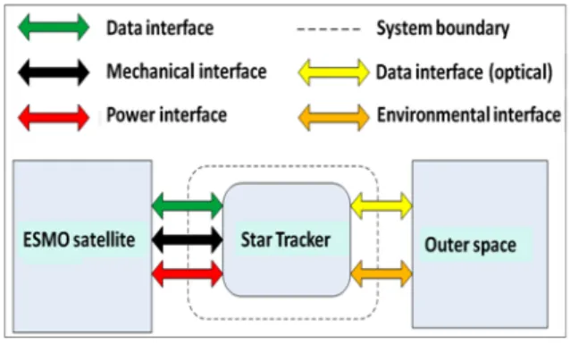
First, we need to define our system (the Star Tracker) in its operational environment. The situation presented in this chapter corresponds to Moon orbit. In that case, the STR interacts with the satellite and works in space environment.
Next schema presents the STR external interfaces with the ESMO satellite and its environment.
Figure 3: System definition C. Global functional analysis
After identifying the system boundaries, we have determined that the Star Tracker primary function is
to provide satellite reference frame in the J2000 (or ITRF2005) celestial reference system.
This primary function can be divided in three main functions:
Star background acquisition
Computation of the attitude quaternion of
the star background
Management of the equipment
Furthermore these tasks shall be performed under constraints that should be managed through constraint, like:
Operate in space environment (e.g.
Interface with the ESMO satellite Mass & power constraints Performance requirements
Mechanical & thermal environment Electro-Magnetic Compatibility (EMC) Be compatible with the mission analysis
(light from the Moon, the Earth and the Sun shall be excluded of the Field Of View (FOV))
Ensure Failure Detection Isolation &
Recovery (FDIR)
The two first constraint functions shall be performed by all Star Tracker components .
D. Lunar constraints
As this STR is going to the Moon, it will face some particular constraints. The main ones are:
to be operational on unusual trajectories to resist to radiation.
Two moments of the satellite’s life have to be considered: transfer to the Moon and orbit around the Moon. Because of the mission cost constraints, the baseline transfer will exploit the Weak Stability Boundary region of the Earth-Sun-Moon system. Besides, the satellite shall be able to manoeuvre around the Moon. During all this phases, the sensors have to be protected from the light coming from the Sun, the Moon, or the Earth. To ensure this protection, we have designed a baffle with a modular approach. By this way, the design remains flexible to possible mission analysis changes. Radiation management is another very important point. Radiation is responsible both for electrical components degradation and for software errors by Single Event Unit (SEU). All of this may reduce the STR lifetime. To minimise the risk due to such radiations, several solutions exist. We have chosen to use only space qualified components. Besides, the structural box will be built in aluminium, and will be 5mm thick. This thickness has been chosen to afford a supplemental mechanical protection for radiations.
E. Star Tracker control Strategy
The Star Tracker control management has been designed to perform four specific modes:
OFF: the STR is off
Safe/Init: the STR is ON and ready to work. It can check if everything is ok. Lost In Space (LIS): it is the STR
nominal mode. It allows computing the attitude of the satellite.
TRACKing (TRACK): the STR can compute the attitude with more accurate performances (greater precision in less time). If this mode does not converge, the
STR mode changes automatically to LIS mode
These modes are managed by the On Board Data Handling (OBDH) and Software commands. If an error occurs, the STR comes back to Safe mode. Next figure presents the four STR modes and their transitions.
___________________________________________ Figure 4: Mode management
F. Star Tracker decomposition
The attitude computation basic concept has pointed out the main activities to be performed by the ST. They structure the Star Tracker breakdown and the interfaces. They are composed of the classical sub-systems (Optics, Hardware, Software and Structure).
Product Tree
Next schema presents a preliminary Star Tracker product tree as a synthesis of the global architecture.
Figure 5: Star Tracker product tree
This product tree includes all the physical elements that compose the STR. It is the preliminary solution to fulfil the STR objectives.
Optics
It assures to detect clearly the stars thanks to an optical system composed of a baffle and lenses.
Hardware
It provides the necessary components to compute the attitude.
Software
It provides the necessary algorithms to compute the attitude.
It ensures the system mechanical integrity and the physical interfaces with the satellite. The structure is as well a mechanical and thermal protection.
Ground Support Equipment (GSE) All the sub-systems shall be tested. So the GSE is the support that will be necessary to develop and test the STR. It includes the labs, the models that will be developed to validate the STR and the computers that will simulate certain functions, etc. More detailed information are given in the part VI. Hardware sub-system.
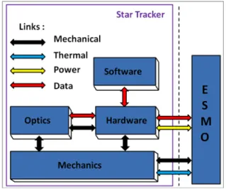
Sub-systems interactions
All sub-systems interact with each other through different links. Next figure presents an overview of those interactions.
Figure 6: Sub-systems interactions G. Physical architecture
As it has been said, the physical structure allows the STR to be a consistent and resistant component of the ESMO satellite. The physical architecture of the STR is the proposed solution to the identified functions. It is presented on the next picture, as a result of modelling analysis.
Figure 7: Physical architecture of the STR
V. OPTICS SUB-SYSTEM
A. Optics main purpose
The optics sub-system is essential for the quality of the image and thus the determination of the attitude of the satellite. This sub-system is going to lead the light toward the electronics part of the star tracker. The number of lenses, their material, their diameter, their thickness and curvature are the parameters that need to be tuned to have a design meeting the requirements. The optical system of a star tracker is not a simple system: space application to optics makes it very challenging. We have to consider radiations, thermal issues, earth or moonlight and others.
The final design is the following
Figure 8: Lenses system
On the above figure, we can see the final six lenses system with the detector being the last surface. Three different wavelengths at three different places in the field of view are represented to show that the image is, at the end, focused on the detector.
B. Functional requirements
As a result of Star Tracker mission analysis, the following functional requirements have been identified:
The optical train of the star tracker shall set at least 6 stars (2 triads) on the detector
The detector shall be protected of the Sun / Earth / Moon light by adequate means
C. Performance requirements
The sensor of the star tracker is an APS750. The associated performance requirements are:
It shall be able to detect a star with a signal to noise ratio of 4
The image resolution shall be optimized to provide spot diagram within 2 pixels of diameter
The energy encircled criterion of at least 70% in a circle of 2 pixels (40 microns) diameter shall be met
D. Design requirements
As far as design is concerned, the main requirement is:
The optical system shall give spot diagram of 2 pixels diameter and shall meet the 70% criterion with temperature and pressure variations E. Optics design analysis results
The minimal number of detected stars required by the software in order to detect the Star light, led us to compute: a FOV (Field Of View) of 20° and a
Focal Length of 60.15mm.
A baffle will protect the lenses from unwanted rays. From the SNR (Signal to Noise Ratio) required by the software team and from the detector performances, the entrance pupil diameter computation leads to 32.9mm.
Simulations were then made in order to compute lenses properties like material, radius of curvature, thickness and diameter.
For a good system performance, the following assumptions were defined:
Spot image within a diameter of 40 microns (2 pixels) – smaller spot would give difficulties to differentiate star from cosmic rays – bigger spot would give a worse image quality
Energy encircled of at least 70% within 40 microns (2 pixels)
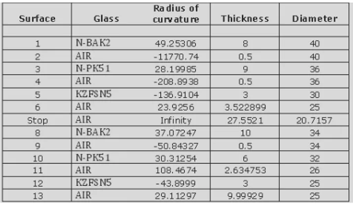
Based on these criteria, the following final design was obtained:
Figure 9: Specifications table
All those specifications give a final system length of 84.20957 mm and a total weight of 94.957361 g. It is also important to notice that all the chosen lenses are available on the market. Schott lenses are selected.
The two following figures present examples of the results at the worst temperature constraint within our temperature range (-20°C to 50°C)
50°C
Figure 10: Spot diagram at 50°C and 0 atm
As we can see on the above graph, at the worst temperature and the worst spot in the FOV (10°), which is the lower spot diagram, there are coma aberrations and chromatic aberrations. The spot image is spread out. Thus, we look at the most important criterion in the graph below.
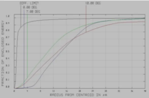
Figure 11: Energy encircled at 50°C and 0 atm In figure 3, when looking at the red curve which corresponds to a light ray that would come from the extremity of the FOV (10°), we see that we have about 75% of the light energy within a circle of 40 microns diameter or 2 pixels. At the worst case scenario: 50°C, 0 atm, 10°FOV the design is compliant with the requirements.
Finally, a tolerance budget was established to determine the range of allowed displacements for the lenses system support. These displacements can be due to temperature variations, mechanical movements or material dilatation.
Figure 12: Lenses tolerance budget
The lenses tolerance shows that the optical sub-system appears to be not very sensitive to motion. It also means that the construction process will not be so long and will not be so expansive.
VI. HARDWARE SUB-SYSTEM
This part presents the hardware part of the electronics. Thus the considered sub-system is the Printed Circuit Board (PCB) of the STR.
A. Hardware sub-system main purpose
The main purpose of the electronics (hardware sub-system) is to provide an attitude quaternion (through electronic data) to the On Board Data Handling (OBDH) from the stars’ light that passes through the optical train. This purpose shall be accomplished in a spatial and moon environment.
Figure 13: Physical perimeter of the PCB.
The PCB shall be supplied in energy by an external power. The Software is not included in the hardware sub-system. It belongs to another one (see §VII). In this paragraph, only the physical components are considered.
B. Functional analysis
To indentify the purposes and constraints the hardware sub-system has to fulfil, a functional analysis has been done, considering the PCB as the sub-system.
Thus, given the primary and constraint functions identified in the global architecture (§IV.C.), each of these functions has been divided into sub-functions. This decomposition stops when a single component is identified to accomplish this function. For instance the function Star background
acquisition has been divided in 4 sub-functions:
1. transform the light data into analogical data 2. transform the analogical data into numerical
data
3. detect centre of the stars from the numerical image
4. store the data (centre of stars)
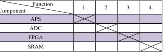
In order to check if each function has been allocated to a single component, allocation matrixes have been created. Given the subdivision made previously, below is an example of what have been made for each function:
Function Component 1. 2. 3. 4. APS ADC FPGA SRAM
Figure 14: Example of allocation matrix
C. Hardware physical architecture and design 1. Physical architecture
Below is a diagram describing the physical architecture that can perform the functions identified by the functional analysis.
_
Figure 15: Physical architecture
The electronic board is divided into two separate boards: the first one is made of the CMOS sensor, its Analogical to Digital Converter (ADC) and it is physically linked to the optical train. The second one is the main board which is responsible for processing the images and for calculating the attitude.
2. Description of the Hardware components
CMOS sensor
The CMOS sensor takes the sky image, which is an Active Pixel Sensor (APS). Then, the ADC on the first board will convert the analogical signal from the sensor to a numerical signal that can be used by the second board.
The selected Sensor is: APS750 FAST
This APS has been designed by the laboratories of the CIMI in ISAE-SUPAERO. It has an embedded sequencer in order to simplify the conception of the sensor commands. Furthermore it has a windowing
mode that enables to process only a determined window of the image.
The selected ADC is: LTC2226H FPGA
The image is then transmitted to the FPGA. This component must perform different tasks concerning the images processing. Those tasks are to:
Manage the acquisition of the images Synchronise the acquisition of the images Deskew the picture (as the satellite is rotating
when the sensor is taking an image)
Delete all noises and possible errors by comparing two succeeding images
Detect the centres of the stars on an image The selected component is: A3PE600
Microcontroller
The microcontroller, which receives the centres of the stars, must:
Compute the attitude
Manage the different modes of the Star Tracker (LIS, TRACK, Safe/Init, OFF)
Handle the communication with the satellite via the CAN bus interface
Handle the housekeeping
Originally the computation of the attitude was to be done in the OBDH and there was no µc. Due to a change of design, a µC has been added in order to manage real time functions.
The selected component is: TSC695FL (ERC32
Single-Chip)
The ERC32 is a space qualified component used in ESA projects. The chosen version (TSC695FL) is a low consumption version.
DC/DC converter
The DC/DC converter will provide the energy to the components by converting the voltage given by Electrical Power Supply (EPS) from the satellite. It should also protect the components and the satellite from electrical failure.
Clock
The clock is provided to the FPGA by an oscillator. The FPGA transmits then the clock to the microcontroller.
ADC and sensors for the housekeeping
On the second board, there is another ADC linked to the sensors. These sensors will monitor the voltages, the temperatures and the current. They are
part of the housekeeping functionality managed by the microcontroller.
Memory
The Electrically Erasable Programmable Read-Only Memory (EEPROM) is used to store the microcontroller software. The two Static Random Access Memories (SRAM) are used for the images processing and for the communication between the microcontroller and the FPGA (for instance the FPGA gives the centres of the stars to the microcontroller via a SRAM).
The selected EEPROM is: AT28C040 The selected SRAM is: 3D SR32M32VS8140 D. Hardware integration
1. Ground Support Equipment In order to validate the PCB architecture, several models will be built. This will allow us to identify mistakes and verify our design.
A first simplified model with main components shall be built to check the overall architecture our Star Tracker.
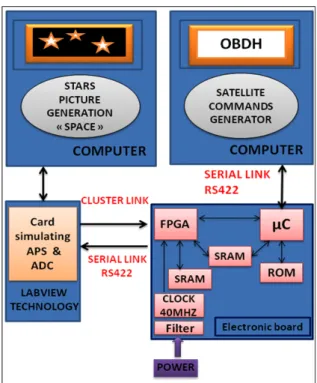
The following picture represents a schema of the future PCB test bank.
Figure 16: Test bank of the PCB
The test bank is composed of two computers and the electronic card.
The first computer simulates picture acquisition with Labview technology. The Acquisition simulation consists of three steps. First, it generates star pictures as close as possible to reality.
Secondly, it converts analogical picture to digital. Finally, it sends numerical data to the electronic card.
The second computer is used to simulate communication between the OBDH of the satellite and the Star Tracker through its electronic system.
2. Test plan
According to requirements analysis, a validation plan has been set up, so as to first verify and validate separately all the PCB functions, and then the validity of the components analysis.
Several primary tests shall be done separately in order to validate all the main PCB functions. For example the first tests to be done are described on the following diagram:
Figure 17: Test plan Power management
This step checks if the power management delivers the required voltages to all components.
Analogical welding
This step tests the welded components on the PCB and the acquisition (with Lab view technology). CAN BUS
These tests must be done after the power management and analogical tests because all board components and power supply must be properly connected. The two kinds of tests that shall be done separately are:
Digital part: Test Digital Converter (with Labview technology) can be done separately from the PCB
Board Communication: the communication between all board components (like clock
transmission) and the communication between the PC and the OBDH
Sub-systems (functions and performances)
This section needs the Software, since its purpose is to test the robustness of algorithms.
• FPGA (program) • µC (program)
• Memories capacities (SRAM and PROM) PCB assembly
This phase consists in testing the global system in operational conditions, and validating all the requirements.
This validation plan is still under construction and will be improved during the next phases of the project.
VII. SOFTWARE SUB-SYSTEM A. Embedded software
The main function of our STR is to compute the satellite attitude. That is why, at the beginning of the project, we concentrated on writing and testing algorithms. As these first steps were very promising, we are now working on designing the whole software. We present here a high-level functional analysis, to identify all functions we shall perform. Then, we insist on the core of our work: how to compute attitude from stars light.
1. Functional analysis Embedded software has two main functions:
to compute the satellite attitude to make this computation possible.
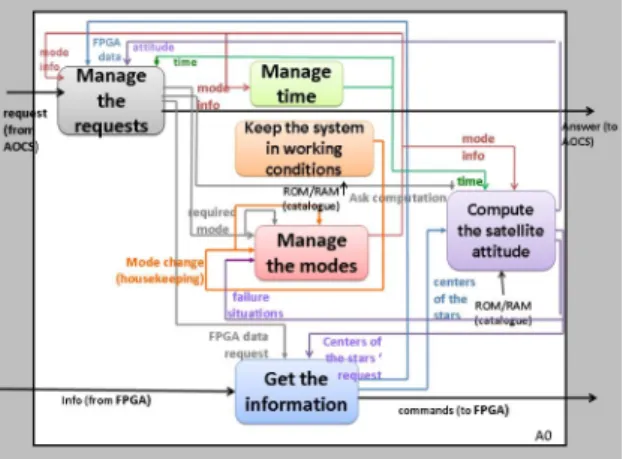
Two different hardware components are supporting this software: a FPGA and a microcontroller. We present the global Structure Analysis and Design Technics (SADT) analysis for both the FPGA and the µC software in the following schema. The goal of those diagrams is to identify all the functions to be performed and how they are linked.
Figure 18: µC software, A0 diagram
We can identify six main functions in the microcontroller software A0 diagram. Five of them are support functions:
manage the requests (communication) get the information (communication) modes management
time management
housekeeping management
The last function, to compute the satellite attitude, is the core of this software.
Figure 19: FPGA software, A0 diagram
The FPGA software is responsible for processing pictures and communicating with sensors.
2.
3. From stars light to satellite attitude
Task repartition between FPGA and µC softwares Two different hardware components are supporting this software: a FPGA and a microcontroller
.
The FPGA is a very good image processor, because it works in parallel. But it allows no real time complex computation: that is why we choose a microcontroller to deal with these functions. The next diagram presents how the work is divided between FPGA and microcontroller softwares.Figure 20: FPGA and µC softwares roles
The optics system gives to the Software sub-system raw pictures, which are processed in FPGA for finding centres of stars in the pictures. Those are
used in the microcontroller to compute the satellite attitude.
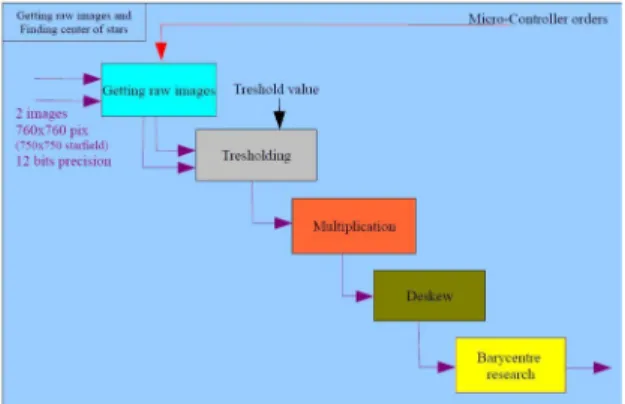
Figure 21: µC software’s A1 diagram, “compute the satellite attitude”
When asked by the µC, the FPGA gets two raw images and apply a threshold on it to remove noise. Then, we multiply these two pictures in order to remove some possible aberrations linked to environmental constraints such as cosmic rays. The next operation consists in deskewing the image to remove the error caused by the rotation of the satellite during the integration time. The image can now be processed. Then the software draws a fictive window around non-black pixels, and researches the centre of the detected star.
Attitude computation in the microcontroller
The microcontroller has to determine the position of the satellite (through an attitude quaternion) thanks to the data given by the FPGA: the centres of stars in the memory.
Figure 22: µC software’s A1 diagram, “compute the satellite attitude”
Those are the realized tasks:
First, for each star the algorithm looks for other stars in order to compute triads. For each star the algorithm tries to find three other stars in the appropriate distance ranges, so as to
create three triads. As soon as it managed to do so, or tried all the stars, it saves the computed triads and makes the computation for the next star.
Secondly, because of the previous operation, some triads appear several times. That is why there is an algorithm that cleans the triads; it suppresses the redundancies in order to have a
list of cleaned triads.
Then the list of cleaned triads is compared to the catalogue to see if some triads match, these are called recognized triads.
Eventually, the attitude quaternion is computed thanks to the recognized triads.
Increasing performances: creating different operational modes
This process finds the attitude of the satellite, but is quite slow: the attitude should be computed in less than 10s.
Why should we process the whole sky whereas we already know where we are? That’s why we have designed a new operational mode, the tracking mode.
There are several changes compared to the previous one.
First, thanks to the previous quaternion, an estimation of the expected stars is done. Thanks to these expected stars, the µC sends
information to the FPGA concerning the tracking window. The FPGA creates a window of 10*10 pixels where the star is expected. Then the centre of the star is determined by computing the barycentre of the pixels weighted by the intensity.
When six stars have been recognized the algorithm stops.
This mode is faster than the previous one; all the tasks should be done in less than 0.1s.
4. Next software developments We are currently developing the architecture of the µC software. The objective is to program old and new functions on a new software test bench. Just after having done the functional analysis, the next step of the development of the FPGA software is to begin the implementation of basic functionalities using VHDL. These functionalities will be tested on a BreadBoard (BB), using real images of the sky or simpler images drawn (in a first time). As soon as the basic functions are operational, our main objective is to make them quicker and less memory-consuming. The hardware to be used to realize the BB is slightly different from the one which is planned to be implemented on the STR. So some slight modifications shall be done finally.
B. End-to-end simulator
1. Simulator purposes
The second important step in the Software development is to design and build an end-to-end simulator to evaluate the performances, to test and to validate the different parts of the software. This simulator will have two parts. First, it shall simulate the STR environment, including starry sky and interaction with the OBDH. Secondly, it shall simulate the STR itself.
2. First steps
Two simulations have already been run on Matlab. The current environment simulator imitates the sky. The objective is to reproduce what the sensor will actually see. The diffraction due to the optics and the trail due to the integration time of the sensor are taken into account.
Figure 23: Current environment simulator
The current STR simulator simulates the algorithms which will be used on the FPGA and the microcontroller to process the pictures and to compute the quaternion. The objective is to validate them and determine the performances in term of precision.
For instance below is the preliminary Simulink diagram of the STR:
Figure 24: Preliminary Simulink diagram of the STR
3. Next developments
From now on, we have to work in two different directions for the environment simulator. First we are going to develop a simulation of interaction with OBDH, in nominal and non-nominal cases. Then, we will extend our sky simulator to a dynamic sky simulator. As soon as the mission analysis is over, we will develop a simple orbital model.
The STR simulator will be improved and progressively be replaced by the STR itself.
VIII. PROSPECTS AND EVOLUTIONS
This part summarizes the current status of the STR and the future progress plan.
A. Current Status
The following table presents the actual status of each sub-system.
Sub-systems Status
Software Functional analysis Simulator program on
(Matlab) Some algorithms
Electronics Functional analysis
Electronic Board design including choice of components
Mechanics Global model on CATIA Resonant frequencies analysis
Optics Determination of lenses tolerance and errors Optical baffle design Figure 25: Current status of the project B. Progress and next steps
Now, the main purpose is to know how we will test each system of the STR to be sure that our product is qualified. Each sub-system is developed in parallel. The global development approach is shown on the picture above:
As each subsystem is developed in parallel by different teams, these models are also a chance to check the progress of all the teams and to check that all subsystems interact correctly with each other. The first step is to build the BB model with a view to testing the main functions of the electronics board. Therefore, this BB shall not include an optic baffle: the sky will be simulated by a computer that shall provide the images directly to the FPGA. Similarly, another computer shall simulate the OBDH. The BB model will be ready before the end of June 2010. Then we will test all electronics and software.
Building this BB will enable us to check the compatibility of the work done by the software team and the hardware team.
The hardware team works on the electronics board design; they are assisted by an electronics engineer working at EREMS (EREMS Company is specialized in the design and the realization of electronic equipments).
The software team works on the algorithms implantation. They are assisted by some of ISAE-SUPAERO researchers and professors.
C. Project schedule
Below is the schedule of the STR development
.
Figure 27: Schedule of the STR development D. Project complexity
The STR project is a complex project. As it is a student project, it implies some particularities. The main ones are:
the integration with all the ESMO –ESEO teams though EUROPE continent
the availability of technical support in SUPAERO
the students teams turn-over
1. Technical complexities In SUPAERO we are time limited because of several reasons. First, we must use space-qualified components because of the environmental constraints. Developing such components requires long processes. Secondly the experts at SUPAERO can provide some help but are limited because of time-constraints, since they are not full time working on this project.
2. The European context To reduce the distance, the ESMO-ESEO teams communicate thanks to the ESMO network on internet. We have also one or two workshops per year at ESA, where every team is represented and all the teams can work together about the project. The advantage is to benefit from intercultural techniques and assets and improve the team building spirit.
3. The teams turn-over
The project is a student program and concerns mainly the second year students of ISAE-SUPAERO and some ISAE master students. Every year the team members change.
These changes increase the complexity of the project. The progress of the project is slowed down while the new teams learn all what have already been done on the project.
In order to reduce the turnover risks, document shall be written each year by the current team. This document shall, for instance, describe, comment the status of the project, clarify the global organisation, etc. and share the lesson learned.
E. Future of the project
Concerning the future of the project, a space association shall be created in SUPAERO, gathering all space student projects in SUPAERO. This association shall ease the transition of such projects. The main advantage of this proposal is to involve any interested student – whatever his grade. Consequently, the progress of the project will be improved. For example the new teams could be created before the holidays and assure the turn-over of the projects.
IX. Conclusion
Finally we have successfully performed a preliminary design of a Star Tracker throughout an accurate and methodical analysis of this system. This is an innovative design: we will use an APS sensor, a FPGA and a microcontroller to provide the ESMO satellite with an attitude quaternion. Furthermore, we are developing a software end to end simulation in order to be able to completely foresee the comportment of the Star Tracker in its lunar environment. This has provided us with a rewarding experience on space project, and allowed us to develop technical, management and teamwork skills.
This ongoing project shall continue and should be, by the end of 2014, the first European student mission to the Moon. It will prove that students have the ability and the boldness to cope with the intricacies of what will be part of future space missions.
X. Acknowledgement
The authors would like to thank all the people involved in this project and in particular: Arnaud Dion, FPGA specialist (ISAE-SUPAERO, PhD) , Pr. Jacques Lamaison, head of Computer science and Automatics Laboratory (ISAE-SUPAERO) and Thomas Baldran, (engineer at EREMS, space electronics expert) for his invaluable help all along the year.