DÉVELOPPEMENT ET VALIDATION DES
MATÉRIAUX MÉTALLIQUES POUR STENTS
CARDIOVASCULAIRES BIODÉGRADABLES PAR
DÉPÔT ÉLECTROLYTIQUE
Thèse présentée
à la Faculté des études supérieures de l‟Université Laval dans le cadre du programme de doctorat en génie de la métallurgie
pour l‟obtention du grade de Philosophiae doctor (Ph.D.)
DÉPARTEMENT DE GÉNIE DES MINES, MÉTALLURGIE ET MATÉRIAUX FACULTÉ DES SCIENCES ET DE GÉNIE
UNIVERSITÉ LAVAL QUÉBEC
2011
Résumé
Les stents coronariens métalliques dégradables émergent comme une alternative possible aux stents permanents fabriqués à partir de métaux résistants à la corrosion comme l'acier inoxydable 316L. Le fer pur est un candidat intéressant pour les stents dégradables en termes de propriétés mécaniques, de dégradation et de biocompatibilité. Ce projet est le premier à étudier la faisabilité d‟utiliser l'électroformage pour produire le fer comme matériau structural dans les stents dégradables. Dans ce projet, un processus de dépôt électrolytique a d‟abord été développé. Les couches de fer produites ont une microstructure fine, une limite élastique élevée ainsi qu‟une résistance à la traction ayant des valeurs comparables à celles de l'acier inoxydable 316L. Un traitement thermique de recuit à 550 ˚C pendant 1 h a produit une recristallisation dans le fer et a amélioré sa ductilité de 8 à 18 %. Des tests de corrosion par polarisation potentiodynamique et par immersion statique et dynamique ont permis l‟étude de la dégradation du fer électroformé en solution de Hank. Il a été montré que le fer électrodéposé se corrode plus rapidement que le fer Armco ® déjà implanté comme stents biodégradables. L'effet de la densité de courant en tant que paramètre de l'électroformage sur la microstructure et la dégradation de fer a aussi été étudié. L‟étude de diffraction d'électrons rétrodiffusés (EBSD) a montré que différentes microstructures, y compris la taille des grains et la texture, peuvent être produites à différentes densités de courant de 1 à 10 A dm-2. Le plus haut taux de dégradation a été obtenu pour le fer fabriqué à 5 A dm-2, car celui-ci possède la plus petite taille de grains et ceux-ci sont équiaxes avec des orientations aléatoires qui présentent un plus grand volume de joints de grains entraînant un taux de dégradation plus rapide. Enfin, le procédé d‟électroformage a été appliqué avec succès pour la fabrication de mini-tubes de fer. Les mini-tubes de fer ont été électroformés sur les échantillons cylindriques d‟étain qui ont été décollés par fusion du substrat après le processus. Les mini-tubes ont ensuite été utilisés pour la fabrication de stents de fer par découpe au laser. Les stents de fer ont montré une taille moyenne des grains de 5 µm après recuit et décapage à l'acide. Cette taille du grain est plus fine que celle généralement obtenue pour des stents SS 316L et pourrait fournir des propriétés mécaniques élevées et une dégradation ciblée pour les stents de fer électroformés.
Abstract
Degradable metallic coronary stents have emerged as possible alternatives for permanent stents fabricated from corrosion-resistant metals such as 316L stainless steel (316L SS). Pure iron has shown to be an interesting candidate for degradable stents in terms of mechanical properties, degradation and biocompatibility. This project is the first to investigate the feasibility of using electroforming process for production of iron for degradable stents where the material is used for a load-bearing application. In this project, firstly, an electroforming process was developed. The produced iron foils showed a fine microstructure and high yield and tensile strength were also obtained comparable to those of 316L SS. Annealing at 550˚C for 1h induced recrystallization in iron and improved its ductility from 8 to 18%. The investigation of the degradation of electroformed iron in Hank‟s solution using potentiodynamic polarization, static immersion and dynamic degradation tests showed that it corrodes faster than Armco® iron previously investigated for degradable stents. The effect of current density as an electroforming parameter on the microstructure and thereby the degradation of iron was also studied. Electron backscatter diffraction (EBSD) showed that different microstructures including grain size and texture were produced at different current densities from 1-10 A dm-2. The highest degradation rate was obtained for iron fabricated at 5 A dm-2 since it possesses small grain size and equiaxed grains with random orientations providing more grain boundary volume can be held responsible for its faster degradation rate compared to the other iron samples. Finally, the electroforming process was successfully applied for the fabrication of iron tubes. Iron tubes were electroformed on Sn cylinders which were separated from them by melting after the process. The tubes were then used for the fabrication of iron stents by laser-cutting. Iron stents fabricated from electroformed tubes demonstrated an average grain size of 5 µm after annealing and acid-pickling. This grain size is finer than what usually obtained for 316L SS stents and could potentially provide high mechanical properties and targeted degradation for electroformed iron stents.
Preface
During the last decade, degradable metallic stents have been developed and investigated as alternatives for the currently-used permanent cardiovascular stents. Degradable metallic materials could potentially replace corrosion-resistant metals currently used for stent application as it has been shown that the effect of stent is temporary and the permanent presence of stents after the arterial remodeling could not provide any beneficial role. Although corrosion is generally considered as a failure in metallurgy, the corrodibility of certain metals can be an advantage for their application as degradable implants. These materials do their job to provide the required scaffolding effect of stent and degrade thereafter. The candidate materials for such application should have mechanical properties ideally close to 316L stainless steel which is the gold standard material for stent application in order to provide mechanical support to the diseased arteries. Non-toxicity of the metal itself and its degradation products is another requirement as the material is absorbed by blood and cells. Based on the mentioned requirements, iron and magnesium alloys have been the investigated candidates for degradable stents.
This doctoral project is included in a general program for design, development and evaluation of new candidate materials for degradable stents. The primary studies on degradable metallic stents included the implantation of the candidate metals in animals and the evaluation of their biocompatibility and degradation. However, our approach is to study the effect of metallurgical conditions of the candidate metals on their mechanical properties and degradation behavior based on the requirements for stent applications before proceeding to in vivo implantation. This approach could provide us with the insight on the effect of processing method, microstructure and composition of the investigated metals on their mechanical properties and degradation mechanism in order to tailor the desired properties. In this context, we also propose for the first time, the application of electroforming for the production of degradable iron-based stents. Electrodeposition is an electrolysis technique mainly used for production of coatings on metals to improve their performance. It is an ideal process for fabrication of small thin-walled metallic objects with different shapes, sizes and properties since it produces the metallic film layer by layer.
Therefore, this project focuses on the development and evaluation of iron-based metallic materials by electroforming for degradable stents.
This doctoral project was carried out under the direction of Professor Diego Mantovani and co-direction of Professor Michel Fiset. It consisted of 1) design and development of the electroforming technique, 2) fabrication of flat iron samples by electroforming, 3) adjustment of the electroforming parameters to produce metallic foils with low surface roughness and porosity, 4) the evaluation of microstructure and mechanical properties of the foils, 5) the study of the effect of electroforming current density on microstructure and degradation of the foils and finally 6) the fabrication of iron stents from electroformed iron tube and their microstructural evaluation.
This thesis has been prepared as an article insertion thesis and includes three journal articles in which I have acted as the principle researcher and the first author. The first article entitled: Electroformed iron as new biomaterial for degradable stents: Development process and structure–properties relationship, co-authored by Dr. Frederic Prima, Prof. Michel Fiset and Prof. Diego Mantovani, was published in the journal: Acta Biomaterialia, 2010, Vol. 6, Issue 5, P. 1726-1735. My contribution to this article was firstly the design of the experimental set-up and then performing of the experiments including: electroforming, mechanical-tensile testing, sample metallographic preparations for microstructural studies and corrosion testing. EBSD studies were carried out by Dr. Frédéric Prima. I subsequently prepared the first draft of the article which was revised by the other co-authors before submission.
The second article entitled: Electroformed pure iron as a new biomaterial for degradable stents: In vitro degradation and preliminary cell viability studies, co-authored by Agung Purnama, Prof. Michel Fiset, Prof. Jaques Couet and Prof. Diego Mantovani, was published in the journal: Acta Biomaterialia, 2010, Vol. 6, Issue 5, P. 1843-1851. My contribution to this article was firstly the design of the experimental set-up and then performing of the experiments including: material production by electroforming, sample preparation for microstructural studies, degradation testing and cell viability assays, degradation testing including static and dynamic tests and the study of the degradation mechanism and products after the tests. The cell viability assays were performed by my colleague, Agung
Purnama, PhD candidate, at Laval Hospital Research Center. I subsequently prepared the first draft of the article which was revised by the other co-authors before submission
The third article entitled: Effect of electrodeposition current density on the microstructure and the degradation of electroformed iron for degradable stents, co-authored by Dr. Sofiene Amira, Dr. Frederic Prima, Dr. Ahmed Rahem, Prof. Michel Fiset and Prof. Diego Mantovani, was submitted to the journal: Materials Science and Engineering: B on September 2, 2010. My contribution to this article was firstly the design of the experimental set-up and then performing of the experiments including: material production by electroforming at different current densities, heat treatment of the fabricated foils, degradation and corrosion testing, and sample preparation for microstructural studies. EBSD sample preparations and studies were carried out by Dr. Sofiene Amira at Aluminum Technology Centre; National Research Council Canada in Chicoutimi under the supervision of Dr. Ahmed Rahem. I subsequently prepared the first draft of the article which was revised by the other co-authors before submission.
I wish to express my deepest appreciation to my thesis advisor, Prof. Diego Mantovani, for giving me this opportunity to be part of his team and to work on this exciting project. I also appreciate his insight, guidance and continuous encouragement throughout this research. I would also extend my gratitude to my co-advisor Prof. Michel Fiset for his insight and knowledge and his valuable comments and discussions through my Ph.D. studies. I am also thankful to my thesis evaluation committee, Dr. Matthias Peuster, Dr. Frédéric Prima, Dr. Dominique Dubé and Dr. Gaétan Laroche.
I am grateful to Daniel Macrotte, Michel Savard, Vicky Dodier and Marie-Josée Bouchard, the technicians of the Department of Mining, Metallurgy and Materials Engineering at Université Laval for their kind collaboration in technical support of the project. I am also really thankful to Maude Larouche for her help, training and collaboration in Metallography Lab and for Optical Microscopy studies, to André Ferland for Scanning Electron Microscopy studies and to Jean Frenette for X-ray diffraction analysis.
Specials thank goes to Prof. Edward Ghali for kindly allowing me to perform the corrosion tests in his laboratory and thanks to his group members for sharing the facilities.
Many thanks to all my colleagues in the Laboratory for Biomaterial and Bioengineering in Saint-Francois d‟Assise hospital for their invaluable support and help particularity to Dr. Hendra Hermawan, Dr. Stéphane Turgeon, Dr. Pascale Chevalier, Dr. Jean Lagueux, Dr. Paula Horny, Dr. Sevaas Holvoet, Dr. Penelope Hale, Frédéric Couet and Agung Purnama. I am thankful to Dr. Frédéric Prima from Laboratory for Physical Metallurgy, École Nationale Supérieure de Chimie de Paris for sharing his valuable insight and knowledge about Electron Backscatter Diffraction studies and for performing some of the experiments in his Laboratory. I also appreciate his valuable new ideas and discussions about the project.
Many thanks to Dr. Sofiene Amira from Aluminum Technology Centre, Industrial Materials Institute, National Research Council Canada for his interest, dedication and kind collaboration in sample preparation and EBSD analysis. Without his valuable help, EBSD studies would be far from completion. I am also grateful to Dr. Ahmed Rahem for his kind collaboration and thanks to Helene Gregoire and Genevieve Simard, the technicians of Aluminum Technology Centre for their help in sample preparation of EBSD studies. I would like to thank Dr. Émile Knystautas from Physics Department of Université Laval who helped me perform thermal and electron-beam evaporation experiments in his lab and for his interest and the time he dedicated to this part of the project.
A special thanks goes to my dear friend, Pegah Seddighian, whose help and encouragement motivated me to start this journey and her care and support prevented me from feeling homesick and lonely during my first days in Canada.
Lastly, I would like to thank my family for their love and encouragement. I am grateful to my parents for their support, patience, and sacrifice in all and every stage of my life. They have always encouraged me to advance my education. And most of all, many thanks to my loving, supportive, encouraging, and talented husband, Hamed, whose scientific collaboration and technical help had a great influence in the progress of my Ph.D. Many thanks to my dear brother, Amir, and my friends for their encouragement and supports.
Table of Contents
Résumé………..…….I
Abstract………..…..II
Preface………III
Table of Contents……….VII
List of Tables………..……..XII
List of Figures……….XIII
Chapter 1.
Introduction ... 1
1.1 Objectives of the project ... 2
1.2 Strategies of the project... 4
1.3 Structure of thesis... 6
Chapter 2.
Degradable Stents- State of the art ... 10
2.1 Cardiovascular disease (CVD) ... 10
2.1.1 Facts and statistics about cardiovascular disease ... 10
2.1.2 Coronary artery disease (CAD) ... 10
2.2 Treatment of CAD by stenting ... 11
2.3 Stent development history ... 12
2.4 Degradable stents ... 14
2.4.1 Polymeric degradable stents ... 15
2.4.2 Metallic degradable stents ... 16
2.4.2.1 Fe-based degradable stent ... 16
2.4.2.2 Mg-based degradable stent ... 17
2.4.3 In vitro degradation of metallic materials for degradable stents ... 19
2.4.3.1 Static immersion ... 19
2.4.3.2 Electrochemical corrosion testing ... 20
2.4.3.3 Dynamic degradation ... 21
2.4.4 Mechanical properties of degradable metals for stent ... 21
2.4.5 Forming methods for stent materials ... 22
2.4.5.2 Powder metallurgy ... 23
2.4.6 Stent tube fabrication ... 24
Chapter 3.
Electrochemical Deposition- Literature Review ... 25
3.1 Electrodeposition ... 25
3.2 Electroforming ... 26
3.3 Structure of electrodeposited metals ... 27
3.4 Mechanical properties of electrodeposited metals ... 29
3.5 Characterization of the structure of electrodeposited metals ... 32
3.6 Electrodeposition of iron ... 33
3.6.1 Iron electrodeposition parameters ... 34
3.6.1.1 Bath ... 34 3.6.1.2 Additives ... 35 3.6.1.3 pH ... 36 3.6.1.4 Temperature ... 37 3.6.1.5 Current density ... 37 3.6.1.6 Cathode ... 39 3.7 Conclusions ... 40
Chapter 4.
Electroformed iron as new biomaterial for degradable
stents: Development process and structure–properties relationship ... 41
4.1 Résumé ... 41
4.2 Abstract ... 41
4.3 Introduction ... 42
4.4 Materials and methods ... 44
4.4.1 Specimen fabrication by electroforming ... 44
4.4.2 Composition, phase and morphology characterization of E-Fe ... 45
4.4.3 Grain size measurements ... 46
4.4.3.1 Methods and sample preparation ... 46
4.4.3.2 Study of microstructure changes in E-Fe by SEM and XRD ... 46
4.4.3.3 SEM observation of E-Fe annealed at 550 and 650˚C and CTT-Fe . 46 4.4.3.4 XRD orientation study ... 46
4.4.4 Mechanical properties... 47
4.4.5 Corrosion testing ... 48
4.5 Results and discussions ... 48
4.5.1 Specimen fabrication ... 48
4.5.2 Composition and microstructure characterization ... 48
4.5.3 Microstructure and grain size measurement ... 50
4.5.3.1 SEM observation of E-Fe with heat treatment ... 51
4.5.3.2 XRD analysis of E-Fe with heat treatment ... 51
4.5.3.3 OIM of E-Fe by EBSD ... 54
4.5.3.4 Microstructure and grain size in annealed E-Fe compared with CTT-Fe ... 57
4.5.4 Mechanical properties... 58
4.5.5 Corrosion testing ... 60
4.6 Conclusions ... 62
Chapter 5.
Electroformed iron as a new biomaterial for degradable
stents: In vitro degradation and preliminary cell viability studies ... 64
5.1 Résumé ... 64
5.2 Abstract ... 64
5.3 Introduction ... 65
5.4 Materials and methods ... 67
5.4.1 Materials ... 67
5.4.2 Microstructure ... 68
5.4.3 Degradation solution ... 68
5.4.4 Static degradation test ... 69
5.4.5 Dynamic degradation test ... 69
5.4.6 Cell viability test ... 70
5.5 Results and discussion ... 71
5.5.1 Microstructure ... 71
5.5.2 Degradation testing ... 72
5.5.2.1 Static degradation test ... 72
5.5.3 Cell viability ... 82
5.6 Conclusions ... 84
Chapter 6.
Effect of electrodeposition current density on the
microstructure and the degradation of electroformed iron for degradable
stents
85
6.1 Résumé ... 856.2 Abstract ... 86
6.3 Introduction ... 87
6.4 Materials and Methods ... 88
6.5 Results ... 90 6.5.1 Microstructure ... 90 6.6 Corrosion testing ... 96 6.6.1 Potentiodynamic polarization ... 96 6.6.2 Static degradation ... 99 6.7 Discussions... 103 6.7.1 Microstructure ... 103
6.7.2 Corrosion and degradation testing ... 107
6.8 Conclusions ... 111
Chapter 7.
Fabrication
of
iron
degradable
stent
from
electroformed tube ... 112
7.1 Résumé ... 112
7.2 Abstract ... 112
7.3 Introduction ... 113
7.4 Materials and Methods ... 114
7.4.1 Tube Electroforming... 114 7.4.2 Stent fabrication ... 115 7.4.3 Characterization ... 116 7.5 Results ... 116 7.5.1 Electroformed tube ... 116 7.5.2 Stent fabrication ... 118
7.5.3 Microstructure ... 121
7.5.4 Discussion ... 122
7.6 Conclusions ... 125
Chapter 8.
General discussion and conclusions ... 126
8.1 Electroforming process ... 127
8.2 Microstructure and mechanical properties ... 128
8.3 Degradation behavior cell viability study ... 129
8.4 Effect of electrodeposition current density on microstructure and degradation ... 130
8.5 Fabrication of stent from electroformed iron tube ... 132
8.6 Limits of the project ... 133
8.7 Perspectives of the project ... 135
Biomedical glossary………..139
List of Tables
Table 2.1- Mechanical properties of different degradable metals compared to 316L SS .... 22 Table 3.1- Tensile properties of electrodeposited metals compared to their wrought
counterparts, adapted from Ref. 79 ... 31 Table 3.2- Composition and operating conditions for iron electrodeposition baths ... 36 Table 3.3- Mechanical properties of iron deposits produced form different baths, adapted
from Ref. 64 . ... 38 Table 4.1- Concentration of impurity elements in E-Fe. ... 49 Table 4.2- Mechanical properties of iron and other candidate materials for cardiovascular
stent fabrication. ... 60 Table 4.3- Potentiodynamic polarization data of electroformed and pure Fe extracted from
polarization curves. ... 62 Table 5.1- Degradation rate values calculated from static test for E-Fe, annealed E-Fe and
CTT-Fe; degradation rates of Fe-Mn alloy and AM60B-F alloys were extracted from the literature for comparison; for all materials, the degradation rate was calculated based on the weight loss during the test. ... 75 Table 6.1- Average grain size and preferential orientation information of electrodeposited
iron as determined from Figure 6.3. ... 92 Table 6.2- Average grain size and preferential orientation information of electrodeposited
iron annealed at 550˚C for 1 h. Data were extracted from Figure 6.4. ... 95 Table 6.3- Corrosion current density and potential of iron electrodeposited at different
current densities: the data were extracted from curves in Figure 6.5. ... 96 Table 6.4- Corrosion current density and potential of iron electrodeposited at different
current densities and annealed at 550˚C for 1 h: the data were extracted from curves in Figure 6.7. ... 98 Table 7.1- Ingredients of Super Iron Out® powder used in pickling of iron stents ... 115 Table 7.2- Dimensional parameters of iron stent. ... 119 Table 7.3- Composition of different points in laser-cut tube (A), annealed cut tube (B) and
List of Figures
Figure 1.1- Flowchart diagram of the experimental strategy of the project ... 7
Figure 2.1- Percentage of different causes of deaths in Canada in 2005, adapted from Ref.14 ... 10
Figure 2.2- Developmental process of atherosclerosis, adapted from Ref. 15 ... 11
Figure 2.3- Stenting procedure: the stent is inserted into the artery using a catheter; it is expanded and positioned by inflating the balloon; the stent remains in place and hold the artery open. adapted from Ref. 19 ... 12
Figure 3.1- Electroplating process: the cations are reduced on the surface of cathode upon the application of an electrical current forming a metal layer. adapted from Ref. 66 ... 26
Figure 3.2- Principle of electroforming: the metallic layer formed on the surface of cathode is separated after electrodeposition and used as a separate part. adapted from Ref. 13 . 27 Figure 3.3- Schematic representation of layer growth (a,b) and 3D growth (c), adapted from Ref. 64 ... 29
Figure 3.4- Schematic cross section of the columnar deposit, adapted from Ref. 64 ... 29
Figure 4.1- Schematic of electroforming apparatus ... 45
Figure 4.2- XRD pattern of E-Fe: all peaks correspond to α-Fe. ... 50
Figure 4.3- Electroformed iron a) surface morphology, b) cross section of E-Fe showing its uniform thickness. ... 50
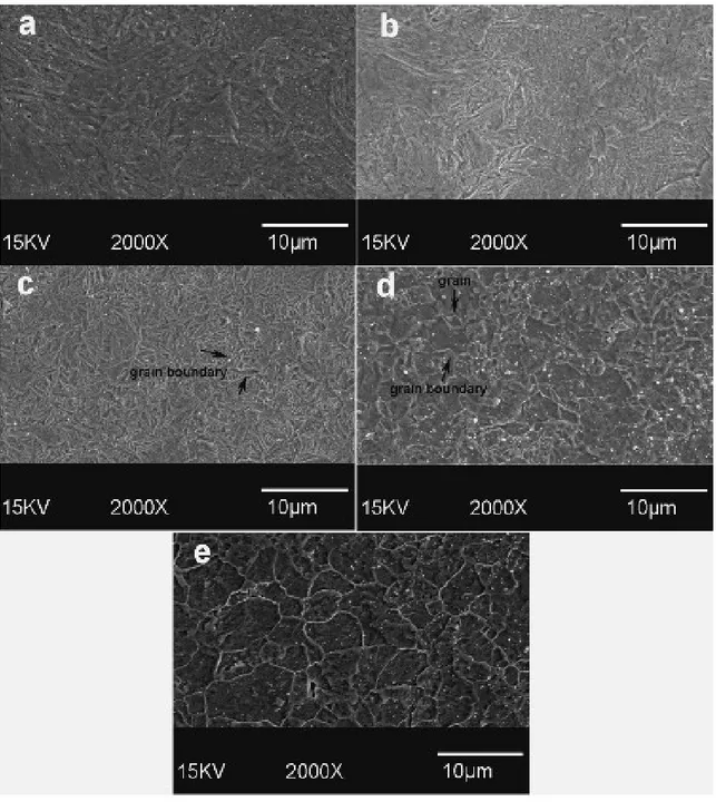
Figure 4.4- SEM micrograph E-Fe: (a) as-deposited; (b) annealed at 250ºC; (c) at 350 ºC; (d) at 450ºC; (e) 550 ºC. The structural reorientation and appearance of grain boundaries is shown. ... 52
Figure 4.5- XRD texture orientation index of as-deposited and annealed Fe. ... 53
Figure 4.6- FWHM of (1 1 0) peak of E-Fe and E-Fe annealed at different temperatures obtained from XRD patterns. ... 54
Figure 4.7- EBSD orientation map of E-Fe: surface microstructure (left) and cross section ... 56
Figure 4.8- Microstructure and grain size distribution of: (a) E-Fe annealed at 550˚C, average grain size 6 µm; (b) E-Fe annealed at 650˚C, average grain size 15 µm; (c) CTT-Fe annealed at 550˚C, average grain size 25 µm. ... 58
Figure 4.9- Tensile test curves for E-Fe (as-electroformed, annealed at 550˚C and annealed at 600˚C) and CTT-Fe annealed at 550˚C. ... 59 Figure 4.10- Potentiodynamic polarization curves for iron: CTT-Fe annealed at 550˚showed
the highest corrosion potential and the lowest corrosion current, while E-Fe had the lowest corrosion potential and the highest corrosion current. ... 61 Figure 4.11- Comparison of different cardiovascular stent materials in terms of mechanical
properties (yield strength and ductility) and degradation rate. 316L SS is not degradable and is presented in this figure as the reference stent material for comparison. ... 63 Figure 5.1- Schematic view of the dynamic test bench. ... 70 Figure 5.2- Microstructure of as-deposited E-Fe, E-Fe annealed at 550˚C and CTT-Fe; the
average grain size of CTT-Fe is much larger than that of E-Fe and annealed E-Fe. .... 72 Figure 5.3- Degradation layer on E-Fe after static test: the cracks are caused by ... 73 Figure 5.4-Degraded surface of (a) E-Fe and (b) annealed E-Fe: neither image shows signs
of ... 73 Figure 5.5- Fe ion release behaviour of electroformed and CTT iron: E-Fe released ahigher
quantity of Fe ion than CTT-Fe did during the testing period. After annealing, the ion release of E-Fe decreased. However, it was still higher than that of CTT-Fe. ... 76 Figure 5.6- IRR of iron calculated from curves in Figure 5.5: the IRR of the studied
material was calculated from the lines. ... 77 Figure 5.7- Degradation layer on the surface of samples after the dynamic test: the layer is
cracked because of dehydration after the test. The morphology is similar to that of the static test. ... 78 Figure 5.8- XRD pattern of degradation layer from dynamic test: goethite (JCPDS No. 29-0713) and magnetite (JCPDS No. 19-0629) were detected in degradation layer. ... 79 Figure 5.9- Cross-section of as-electroformed Fe (a) before and (b) after dynamic test;
annealed E-Fe (c) before and (d) after dynamic test; (e) as-electroformed Fe and (f) annealed E-F after degradation. (a–d) shows the etched cross-sections at 200X, while (e and f) are from as-polished samples at 50X. ... 81 Figure 5.10- Cell viability of iron and 316L SS: the column charts are related to the
(left axis), while the curve is the total cell count measured at 24, 48, and 72 h (right axis). ... 83 Figure 6.1- Surface morphology of electroformed iron deposited at (a) 1, (b) 2, (c) 5 and (d)
10 Adm-2. ... 91 Figure 6.2- Color key code inverse pole figure used for OIM imaging. ... 92 Figure 6.3- Normal direction maps as shown with color key code inverse pole figure and
grain size distribution of iron electrodeposited at : (a) 1, (b) 2, (c) 5 and (d) 10 Adm-2. Column 1 displays the surfaces while column 3 shows the cross-sections of the electrodeposited samples. ... 92 Figure 6.4- EBSD orientation images and grain size distribution of iron electrodeposited at
(a) 1, (b) 2, (c) 5 and (d) 10 Adm-2 annealed at 550˚C for 1 h. Column 1 displays the surfaces while column 3 shows the cross-sections of the annealed samples. ... 95 Figure 6.5- Potentiodynamic polarization curves of iron electrodeposited at different
current densities. ... 96 Figure 6.6- Corrosion rates of iron electrodeposited at different current densities: the rates
were calculated from corrosion current density values presented in Table 6.3. ... 97 Figure 6.7- Potentiodynamic polarization curves of iron electrodeposited at different
current densities and annealed at 550˚C for 1 h. ... 98 Figure 6.8- Corrosion rates of iron electrodeposited at different current densities: the rates
were calculated from corrosion current density values presented in Table 4. ... 99 Figure 6.9- Degradation rate of as-deposited iron calculated from static degradation test
based on specimen‟s weight loss during the test. ... 100 Figure 6.10- Surface morphology of iron deposited at different current densities after static
degradation (after the corrosion products were removed). (a) 1, (b) 2, (c) 5 and (d) 10 Adm-2, Small images on top-left show the same surface at higher magnification. .... 101 Figure 6.11- Degradation rate of electroformed iron annealed at 550˚C calculated from
static degradation test based on specimen‟s weight loss during the test. ... 102 Figure 6.12- Surface morphology of iron deposited at different current densities and
annealed at 550 ˚C after static degradation (after the corrosion products were removed). (a) 1, (b) 2, (c) 5 and (d) 10 Adm-2,Small images on top-left show the same surface at higher magnification. ... 103
Figure 7.1- Schematic view of iron tube electroforming ... 115 Figure 7.2- As-electroformed iron tube: (a) image (b) SEM surface morphology ... 117 Figure 7.3- Cross-section of as electroformed tube (a) and EDS analysis of the white layer
inside the tube (b) ... 117 Figure 7.4- Electroformed iron tube after grinding: (a) image, (b) cross-section and (c)
surface by SEM. ... 117 Figure 7.5- As-cut iron tube: (a) and (b) SEM micrographs and (c) microscopic image of
polished cross-section. ... 118 Figure 7.6- SEM micrograph of annealed cut iron tube (a) before and (b) after acid
pickling. ... 118 Figure 7.7- Polished cross section of annealed laser-cut iron tube (a) after annealing, (b)
after acid pickling. ... 119 Figure 7.8- SEM images of cross sectional (left) and surface (right) of Fe stents: (a,b) laser
cut minitube; (c,d) annealed laser cut minitube; (e,f) acid pickled minitube (stent). . 120 Figure 7.9- Optical micrograph of 2% Nital etched cross-section of (a) as –laser cut, (b)
annealed laser cut Fe tube, and (c) pickled stent. ... 122 Figure 7.10- Microscopic images of 316L SS stent struts adapted from Refs. 148,159,160 .... 125
Chapter 1. Introduction
A biomaterial can be defined as any material used to make devices or to replace a part of a function of the body in a safe, reliable, economic, and physiologically accepted manner 1. In order to achieve that purpose, a biomaterial must be in contact with living tissue and/or body fluids resulting in an interface between living and nonliving substances. Biomaterials used for implants can be metals, ceramics, polymers and composites. The early use of metals as biomaterials has been reported since late 18th century when Fe, Au, Ag and Pt were used as wires and pins to fix bone fractures 2. Metals have high impact strength, high wear resistance, high ductility and the capacity to absorb high strain energy (toughness) compared to other materials. These properties make metals suitable candidates for orthopaedic load-bearing application and fixation devices such as joint replacement, bone plates and screws, as well as dental implants, pacer and suture wires, and cardiovascular stents 1,2. The implantation of cardiovascular stents is among the available treatment options for coronary artery disease the primary cause of which is atherosclerosis or occlusion of coronary artery by deposition of plaque along the artery wall 3. The blockage of the arteries reduces or cuts off the oxygenated blood supply of the heart muscle leading to a heart attack. Stent are metal mesh structures that expand in the artery and hold it open after percutaneous transluminal coronary angioplasty. Stenting is indeed performed to improve the success of balloon angioplasty. In the process of stenting, a stent is mounted on the balloon and is expanded and positioned by inflating the balloon. The expansion of stent pushes it up against the artery wall and when the balloon is deflated the stent remains in place and hold the artery open. The other treatment options for coronary artery disease include medical treatment (in non-severe cases), minimally invasive surgical treatments such as atherectomy and invasive surgical method which is coronary artery by-pass graft surgery. By doing a stent insertion along with balloon angioplasty, the risk of the artery re-narrowing (restenosis) is reduced, and the risk of abrupt vessel closures during or within 24 hours of the procedure is nearly eliminated 4. Although the ideal stent does not exist, the following properties are necessary to make the stent implantation more efficient 1:
Ease of visualization with X-rays High strength to resist arterial recoil
Longitudinal flexibility to pass tortuous vessels Radial elasticity under external compression Fatigue resistance
Minimal induction of hyperplasia of intima Thromboresistance
Biocompatibility
Based on the mentioned requirements, metals including 316L stainless steel, Ni-Ti alloy and Co-Cr alloys have been the most suitable candidate materials for fabrication of stents
1,2 .
1.1 Objectives of the project
This doctoral project was included in a large research program focusing on the development of candidate metals for degradable stents which show uniform degradation mechanism, are non-toxic and possess the necessary mechanical properties for their application as stent materials. Pure iron was selected as the candidate material for this study. Although Armco® iron had been previously studied by Peuster et al 5,6 for degradable stents, their investigations mostly focused on the implantation of iron stents in animal models. Therefore, the evaluation of microstructure, mechanical properties and degradation mechanism of iron from the materials science point of view was necessary. The objective of this project was to investigate the effect of microstructure on mechanical properties and degradation of iron and to explore the microstructural modifications which could increase its degradation rate. The method we decided to pursue in this project for production of iron was electroforming. Electrodeposition method have been previously used to apply coatings on the surface of metallic stents to alter their surface morphology, release drugs, enhance radio-opacity, and prevent corrosion 7. However, it had never been explored for fabrication of a structure for load-bearing applications such as degradable
stents. Currently, the majority of stent materials are fabricated by casting and thermomechanical process. However, it has some limitations especially in production of pure metals which is of high importance in case of stent materials. In casting process, the nature and purity of the elemental material components mixed prior to melting, together with melt practice itself, have aninfluence on homogeneity, porosity and microcleanliness of stent materials. Standard casting processes for metallic implants such as ASTM F138 permit inclusions as thick as 15 μm on a 75 μm length. Such defects are massive compared with stent struts that can be thinner than 100 μm and could represent a serious problem of rupture upon expansion, thus, in selection of material source and in the melting process attention should be paid to purity and chemical composition 8. Powder metallurgy is another metal fabrication method which was investigated by Hermawan et al. 9,10 to develop Fe-Mn alloys for degradable stent. In this process the size, morphology and purity of metal powders, mixing time and conditions, pressing load and sintering conditions including sintering temperature, time and atmosphere can strongly influence the products properties. The risk of this method is porosity which can be included in the final products and is very sensitive to the mentioned processing parameters.
Using electroforming to fabricate stent materials appears to be logical because this method which produces a metallic part by building up the structure of the material layer by layer could be an excellent method for manufacturing thin-walled products. In conventional metal working processes the metal is normally cast as a massive billet or ingot, which needs to be progressively reduced in size to yield a thin-section final product. This involves multiple working processes and can, therefore, be very costly as well as inefficient in terms of energy consumption. However, the production of thin layers and mesh products is by far the biggest industrial use of electroforming. A variety of metals can be electroformed, offering a wide selection of metallic properties for the product of this process. More common metals which are fabricated by electroforming are iron, nickel and copper. In recent years some of their alloys such as Fe-Co, Ni-Co and gold alloys are also produced by this process 11.
Different stent strut thicknesses have been reported in literatures from 75 to 200 μm 12. The electroforming process has the potential of producing layers with different thicknesses
ranging from 10 μm to 5 mm, therefore, our primary objective was to produce iron foils, about 100-200 μm in thickness, by a developed electroforming apparatus and to study the effect of deposition parameters on microstructure, mechanical properties and in vitro degradation behaviour of the fabricated foils. This could permit us to obtain a better understanding of the feasibility of using electrochemically produced iron as a degradable stent material and also to develop a new class of electroformed degradable stents.
The next step of the project was the fabrication of iron stent tubes by electroforming. One of the advantages of electroforming is its specific capability to produce thin walled cylinders, without a joint line 13. This property cannot be obtained by other fabrication methods including casting and powder metallurgy. With those methods, the primary ingot should be rolled to achieve the desired thickness. Tube drilling or drawing will be then necessary to obtain the stent tube. By electroforming, a stent tube could be directly electrodeposited on the surface of a cylindrical substrate in a one step process.
1.2 Strategies of the project
Figure 1.1 illustrates the flowchart of the project activities. The research and experimental work of this project was conducted in five stages. Firstly, the literature review on the current status of degradable stents and electroforming process was done while a series of preliminary experiments were carried out on the microstructural analysis and degradation of Armco® iron using three different degradation tests: potentiodynamic polarization, static immersion and dynamic degradation. These experiments were performed in order to know better the degradation properties of Armco® iron previously implanted as degradable stent. The second stage of the project was to design and prepare a set-up for electroforming of iron based on the literature review. Iron foils were electroformed using the developed set-up and the electrodeposition parameters were optimized. The specimens were fabricated in the form of flat foils since this form was more practical for characterizations. Annealing was also performed on electroformed iron foils to investigate its effect on microstructure and mechanical properties. The study of the microstructure and mechanical properties of the electroformed iron before and after annealing was subsequently performed to investigate if the material had the potential to be applied for degradable stents. A rapid
corrosion testing using potentiodynamic polarization technique was also performed to evaluate the corrosion rate of electroformed iron compared to other materials previously studied for degradable stents. The result of this stage of the project including the electroforming of iron, microstructure and mechanical studies, and corrosion testing are included in the first article.
Although electroformed iron showed interesting mechanical properties and corrosion rate in the previous stage of the project, a more profound study on its degradation mechanism and its biocompatibility was necessary for its application as degradable stent. Therefore, the third stage of the project included detailed in vitro degradation evaluation of electroformed iron using static immersion and dynamic degradation test which simulated the conditions of an implanted stent in the artery in a more realistic way. Also, a series of cell viability assays using primary rat smooth muscle cells were performed on electroformed iron to assess the basic cells response in contact with this material. The results from this part of the project were published in the second article.
As the applications of electron backscatter diffraction in the second stage of the project revealed the presence of a strong texture in the electroformed iron deposited at certain parameters, the fourth part the project was performed to understand how the electroforming process can affect the microstructure and texture of electroformed iron and thereby influence its degradation. This was especially important since different textures and microstructures could potentially change the degradation rate and form of the stent material. This stage of the project included the production of iron foils deposited at different current densities, annealing of the electroformed foils, microstructural and texture investigation of electroformed iron foils before and after annealing and finally degradation testing of iron foils deposited at different current densities in as-electroformed and annealed states. The results of this stage were reported in the third article.
Because the objective of the project was to produce electroformed iron for degradable stents, the final stage was to investigate the feasibility of fabricating stents from electroformed iron tubes. During this stage, the electroforming set-up was modified for production of cylindrical specimens instead of flat foils. After investigating a number of materials as substrate, a cylindrical tin substrate was used to produce iron tubes. The
substrate was separated from the tubes by melting after the electroforming. The iron tubes were subsequently ground and laser cut to obtain iron stents. Suitable annealing and acid pickling techniques were developed during this stage to induce recrystallization and to remove the undesired parts of the stents, respectively. Finally the microstructural investigation was performed on the fabricated stents.
1.3 Structure of thesis
This thesis is presented in eight chapters. The first chapter is a general introduction of the thesis and presents the problem identification and the objectives and strategies of the project.
In the second chapter, a literature review of the current status of degradable stents is presented. It starts with a brief review on cardiovascular disease and its treatment method with stents. A detailed review on material selection, properties and fabrication of degradable stents is then presented.
The third chapter focuses on the electroforming of iron. The first part is allocated to an introduction on electrodeposition and electroforming and in the second part a literature review on the electroforming of iron including the deposition process, parameters and the properties and characterization methods of electroformed iron is presented.
Chapters 4-7 are considered as the result sections of the thesis. They present the experimental approach as well as the results of this thesis.
Literature review and preliminary experiments
Design and preparation of the electroforming set-up
Electroformed iron foils fabrication, process optimization, heat reatment
Microstructural characterization, mechanical properties measurements
and corrosion testing of electroformed iron foils: Article I
Degradation and cell viability studies of electroformed iron foils: Article II
Investigation of the effect of current density on microstructure and degradation of electroformed iron
foils: Article III
Electroforming of iron tubes and fabrication of iron stents
Microstructural characterization of iron stents
Conclusions
Chapter 4 reports firstly the experimental methods for iron electroforming process development, selection of deposition parameters, composition, phase and microstructural characterization of the fabricated iron films, evaluation of the mechanical properties and finally corrosion testing of iron foils. The second part of the chapter presents the obtained results and discussion. The results showed that the electroforming process was successful for production of iron foils with a thickness of 80-100 µm. A strong (1 1 1) texture was observed for electroformed iron with the average grain size of 4 µm which is significantly smaller than the grain size observed for iron produced by casting and thermomechanical treatment. Electroformed iron showed high yield and tensile strength comparable to those of 316L stainless steel which is considered as the gold standard for stent materials. However, the ductility of iron was only 8% and an additional annealing at 550˚C for 1 h was required to improve the ductility. Annealing was found to produce recrystallization in electroformed iron and changed its strong texture to a more randomly oriented microstructure. The corrosion rate of electroformed iron was higher than that of Armco® iron previously investigated as a degradable stent material. This chapter was published as an article in the journal: Acta Biomaterialia on May 2010.
The experimental methods and results of the investigation of the degradation mechanism and preliminary biocompatibility of electroformed iron are presented in Chapter 5. Two in
vitro degradation tests including static immersion and dynamic degradation were performed
on electroformed iron before and after annealing and the results were compared to those of Armco® iron. The degradation rate was calculated and a degradation mechanism was proposed based on the analysis of the degradation layer formed on the surface of the specimens. The form of degradation was identified using microscopic images. Electroformed iron showed uniform degradation with higher rate than that of Armco® iron. The degradation rate decreased after annealing because of the recrystallization and the slight grain growth observed after heat treatment. Cell viability and cell counting essays were performed on electroformed iron to assess its biocompatibility using rat smooth muscle cells (SMC). The results showed that iron had no effect on cell metabolic activity of SMCs compared to the control and 316L stainless steel but reduced the cell number slightly which can be considered as an advantage for application of the material as stent. This chapter was also published in the journal: Acta Biomaterialia, May 2010.
Chapter 6 focuses on the effect of current density on microstructure and degradation of electroformed iron. Because current density is one of the main parameters affecting the microstructure and properties of electrodeposited metal, current density was varied in the range of 1-10 A.dm-2 and its effect on electroformed iron was studied. The microstructure of iron foils was characterized using electron backscattered diffraction to identify the orientation of grains as well as the average grain size. Potentiodynamic polarization and static immersion test were subsequently performed on electroformed iron specimens deposited at different current densities to assess their degradation behaviour. A discussion on the effect of microstructure on degradation of different iron samples is finally presented. This work was submitted as an article to the journal: Materials Science and Engineering: B on September 2010.
In Chapter 7, the fabrication process of iron stents from electroformed iron tubes and the microstructural evaluation of the resulting stents are presented. As the objective of the project was to investigate the feasibility of applying electroforming process for fabrication of stents, the last part of the project was iron tube electroforming. Iron tubes were electroformed on Sn cylinders and the substrates were removed by melting after the process. Tube grinding, laser cutting, annealing and acid pickling were then performed to achieve iron stents. The results showed that the fabrication of stents from electroformed iron tubes was feasible with some modifications to annealing and acid pickling process. Iron stents had an average grain size of 5µm which is smaller than those generally observed in 316L stainless steel stents. This fine grain size is anticipated to provide high strength and ductility to iron stents. However, the mechanical properties of iron stents should be investigated before reaching to any conclusion.
In Chapter 8, concluding remarks of the project are presented and some perspectives to continue this work are suggested.
Chapter 2. Degradable Stents- State of the art
2.1 Cardiovascular disease (CVD)
2.1.1 Facts and statistics about cardiovascular disease
CVD has been the number one killer and the major cause of illness and disability in Canada. It is the most costly disease, putting the greatest burden on Canada‟s national health care system. In year 2005, over one third (33%) of all deaths in Canada were due to heart disease and stroke and according to World Health Organization statistics, it affected both sexes and all age groups 14. Figure 2.1 shows the classification of different cause of deaths in Canada in 2005.
Figure 2.1- Percentage of different causes of deaths in Canada in 2005, adapted from Ref.14
2.1.2 Coronary artery disease (CAD)
Cardiovascular diseases are diseases affecting the heart and circulatory system. The most widespread form of cardiovascular disease starts with damage and occlusion of the coronary arteries and reduction of coronary blood supply to the heart. The most frequent cause of obstruction in a main coronary artery is atherosclerosis 3. Atherosclerosis leads to the formation of plaques of atheroma that can build up within the arterial walls. The
plaque is made up of LDL-Cholesterol, lipids and cellular debris and narrows the diameter of the large and medium-sized arteries. This narrowing of the arteries can lead to a loss of tissue elasticity and loss of oxygen to the arterial tissues, heart muscles and brain tissues and as the damage increases there is increased reduction of blood flow to vital organs, such as the heart or brain, even kidneys and lower extremities. Plaques are also prone to rupture or to ulcerate and then act as a site for blood clot formation (Figure 2.2).
Figure 2.2- Developmental process of atherosclerosis, adapted from Ref. 15
The resulting blood clots (thrombosis), which can block the affected vessel completely, are usually responsible for the more severe clinical manifestations of cardiovascular disease such as ischemia which is the reduction of demanded oxygen of the heart leading to a heart attack and stroke 16.
2.2 Treatment of CAD by stenting
Stent is a small mesh-like tubular scaffold which is placed and then is expanded inside the coronary artery to keep the lumen open. Stenting is a catheter-based procedure in which a stent is inserted into the artery to hold it open following a balloon angioplasty. At present, stenting is performed during about 60 percent of balloon angioplasty cases. In this process, the stent is mounted on the balloon and is expanded and positioned by inflating the balloon.
The expansion of stent pushes it up against the artery wall and when the balloon is deflated the stent remains in place and hold the artery open. In addition to balloon expandable stents, self expanding stents are produced with the desirable diameter and are loaded on a smaller catheter. Once the stent is deployed on the diseased location in the artery, the catheter is withdrawn and the stent expands into the artery 4. Stenting can considerably reduce the risk of restenosis after the angioplasty, however, in about 25% of cases of stenting, the problem of restenosis can still remain which is called in-stent restenosis (ISR). ISR is caused within 3-6 months after stenting by neointimal proliferation which is an excessive healing process after the tissue injury 17. In recent years, different methods are being investigated for the treatment of ISR most of which are focused on its prevention 18. Figure 2.3 shows the stenting process following balloon angioplasty.
Figure 2.3- Stenting procedure: the stent is inserted into the artery using a catheter; it is expanded and positioned by inflating the balloon; the stent remains in place and hold the
artery open. adapted from Ref. 19
2.3 Stent development history
The idea of using stents was firstly introduced by Dotter in 1969 in order to improve the application of balloon angioplasty in the treatment of vascular occlusion by keeping the lumen open and by reducing the risk of restenosis associated to this process. In 1983, he could successfully deploy stainless steel and Nitinol coil stents in animal trial studies. The first human use of stent occurred in 1986 by Sigwart et al 4, but it was not sooner than 1994
when the Cordis Palmz-Schats stent was approved by FDA of the US. Since then stents have been increasingly used as new alternatives in treatment of coronary artery disease. In the first decade after the approval of Palmaz-Schatz stent, several generations of bare metal stents were developed, with each succeeding one being more flexible and easier to deliver to the narrowing site. However, while stents virtually eliminated many of the complications of abrupt artery closure, restenosis persisted. Although the rates were somewhat lower, bare metal stents still experienced reblocking (typically at six-months) which necessitates a repeat procedure 18.
The idea of drug-eluting stent was put forward as a solution for in-stent restenosis to move stent from purely mechanical devices toward pharmacologic advances. Physicians and companies began testing a variety of drugs that were known to interrupt the biological processes that caused restenosis 20. Stents were coated with these drugs, sometimes imbedded in a thin polymer for time-release, and clinical trials were begun. The first drug eluting stent (DES), which was a Cypher Sirolimus-Eluting Coronary Stent made by Cordis Corporation, was approved by FDA in April 2003. The stent was made of stainless steel and coated with Sirolimus as an anti-restenosis drug which inhibits the vascular smooth muscle cell proliferation 21. Since then, some other drug eluting stents have been developed in US and Europe and proved to be successful in reducing the restenosis rate. Although it is proven that DES can reduce the problem of restenosis, it has become obvious that permanent stents generate problems other than just IRS. Also it has been shown that the requirement for stent implantation is temporary and is limited to a short period after stenting during which the arterial remodelling and healing is done. In this context, the development of degradable stents which fulfill the short-term need for a stent and prevent the potential long-term complications of permanent stents can be a logical approach 22. The first degradable stent was developed in 1980‟s from a polymeric material (poly-L lactic acid) and there have been several experimental and clinical studies on implantation of polymeric stents 23. Recently metallic degradable stents have been developed and in 2001, the first degradable metallic stent made from pure iron was implanted in rabbits by Peuster et al 5. In December 2004, the first human implantation of a degradable metal stent (Biotronik magnesium stent) was performed 22. Since then, the development of degradable metallic stents has been increasing rapidly and more human clinical implantation studies of
magnesium stents have been reported. Degradable stents have also the potential to be coated with drugs and to serve as platforms for local drug delivery 24
2.4 Degradable stents
Bare metal stent implantation mainly fabricated from 316L stainless steel, Nitinol and cobalt-chromium alloy has shown tremendous superior effects in various kinds of clinical situations, especially in the field of percutaneous coronary intervention, compared to simple balloon angioplasty. From the studies using intracoronary ultrasound after balloon coronary angioplasty, the two underlying components were identified as the mechanisms for restenosis after balloon coronary angioplasty: tissue accumulation and arterial remodelling. Pathologic remodelling, which occurs late between 3 and 6 months after balloon angioplasty, can contribute as the dominant mechanism of restenosis. Stent implantation can reduce the subsequent restenosis by utilizing its scaffolding effect and preventing the lumen shrinkage as a result of pathologic remodelling. However, it cannot prevent the tissue accumulation within stents, and this is the shortcoming of bare metal stent implantation leading to ISR which occurs in 25% of stent deployments 25.
Also, permanent metallic implants have specific drawbacks which limit their more widespread use. These limitations include long-term endothelial dysfunction, delayed re-endothelialization, thrombogenicity, permanent physical irritation, chronic inflammatory local reactions, mismatches in mechanical behavior between stented and non-stented vessel areas, inability to adapt to growth, and importantly non-permissive or disadvantageous characteristics for later surgical revascularization 22.
Since the major effect of stent implantation is provided by its scaffolding effect, its radial force and endurance have been considered very important. From the ultrasound observations on coronary restenosis, the scaffolding effect of stent is required to last for 6 months. After this period, the presence of stent within the body cannot provide any beneficial effects. Thus, the development of degradable stents, which can fulfill the mission and step away, is the logical approach 23,25. The material for degradable stents is requested to have at least the following characteristics: it must be biocompatible; degradation products of the material must also be biocompatible, the material must stay in the place for
several months before its complete bioabsorption and the radial force of the resultant stent must be enough for scaffolding effect during the requested period 25
2.4.1 Polymeric degradable stents
The first degradable stent was developed by Stack and Clark of Duke University in the early 1980s. They investigated a number of degradable polymers and selected Poly-L Lactic Acid (PLLA) as the stent material. This material has a high tensile strength, permitting robust mechanical design, but requiring long degradation times 26. Currently, most of degradable polymeric stents are fabricated of PLLA and numerous experimental and clinical investigations have been performed about the performance and efficiency of this material as a degradable stent. Tamai et al 27 reported their preliminary results of PLLA degradable stent implantation in human coronary arteries. They performed coronary
angiography and intravascular ultrasound during 6 months after the stenting procedure. The
results showed that all stents were delivered successfully. There were no deaths,
myocardial infarctions, coronary artery bypass graft, or stent thrombosis. However,
Eberhart et al observed inflammatory response to sterilized PLLA stents implanted in the porcine femoral artery and suggested that this tissue responses might be due to the parent polymer compound, additives to the polymer, intermediate biodegradation products, the implant geometry, or combinations thereof 26.
Degradable polymeric stents can be used as platforms for local drug delivery in the diseased coronary arteries. Tsuji et al 28 used the Igaki-Tamai PLLA stent for a new DES system acting as a vehicle for local Tranilast administration which is an atni-allergic drug inhibiting the migration and proliferation of vascular smooth muscle cells. The Tranilast-eluting Igaki–Tamai stents were supposed to reduce neointimal hyperplasia and restenosis after stent implantation; however, there are not yet sufficient experimental or clinical data on these stents to present.
Although a variety of polymer-based degradable stents are currently being commercially developed, there are important drawbacks of polymer stents relate to their intrinsic mechanical properties. Polymers are not able to guarantee the same radial force and limited recoil compared with metal platforms, and their relative bulkiness could limit application in small vessels 22. Also, there are some complications associated with the implantation of
PLLA polymeric stents such as required heating process during balloon inflation and uncontrolled expansion of stent 5. Furthermore, severe tissue responses were identified with some biodegradable polymers in porcine models. Therefore, more trials and development of materials and techniques are necessary to bring these stents to clinical study and confirm their efficiency and safety 29. For polyglycolide (PGA) degradable implant material, it is confirmed that the rapid degradation process and its acidic products are responsible for causing inflammation in surrounding tissues 30.
2.4.2 Metallic degradable stents
2.4.2.1 Fe-based degradable stent
The first degradable metallic stent was fabricated from Armco® iron (Fe >99.8%) and implanted in descending aorta of 16 New Zealand white rabbits 5 . Iron can interconvert between ferric (Fe2+) and ferrous (Fe3+) forms by accepting and donating electrons quite readily, which makes it a useful component for cytochromes, oxygen–binding molecules (hemoglobin and myoglobin), and many enzymes. Iron ions are bound to transferrin (the Fe–transporting protein) during circulation and bound to ferritin (the Fe–storaging protein) when accumulated within cells. Even though iron is essential to life, its excess or deficiency can be deleterious 31. However the results from the implantation of the first iron stent showed no significant evidence of either an inflammatory response or neointimal proliferation, and organ examination did not reveal any systemic toxicity. There was also a maintained stent patency, no thromboembolic complications, and no adverse events during a 6-18 month follow-up period 5. In 2006, another study was performed to evaluate the safety of corrodible iron stent in a peripheral stent design (6-12 mm diameter) in a slotted tube design. Iron stents were implanted into the descending aorta of 29 minipigs which were followed for 1-360 days and 316L SS stents were implanted as reference. The results showed no difference with regard to the amount of neointimal proliferation between 316L SS and iron stents. Also no signs of iron overload or iron-related organ toxicity were observed. Adjacent to the iron stent struts, there was no evidence for local toxicity due to corrosion products. It was concluded that iron is a suitable metal for the production of a large-size degradable stent with no local or systemic toxicity. However, the implantation of Armco® iron stent showed that the stents did not corrode completely during the follow up
period and therefore, faster degradation rate is desirable for iron and further studies have to focus on the modification of the composition and design of the stent to expedite the degradation process 6. In a more recent study, iron stents were deployed in the coronary arteries of juvenile domestic pigs. Cobalt chromium stents were also implanted for comparison. Short-term effects of the implanted stent were investigated after 28 days. Results showed that iron stents started to show signs of degradation without evidence of stent particle embolization or thrombosis without traces of excess inflammation, or fibrin deposition. At 28 days, the surface of the iron stent struts was black to brown and the vascular wall adjacent to the iron stent had a brownish tinge. There were no statistically significant differences in any of the measured parameters between segments implanted with iron and cobalt chromium stents. There were also no adverse effects in the persistent areas
32. Because the study was limited to a short period after implantation, no conclusion could
be drawn about the degradation rate of iron stent. However, the results of long-term implantation of iron stent showed that future efforts have to focus on the acceleration of the degradation rate. The suggested mechanisms are either using iron-based alloys with a more pronounced corrosion rate or increasing the surface of the stent along with reduction of the strut thickness and modification of the stent design5,6.
2.4.2.2 Mg-based degradable stent
Magnesium is another attractive material for biodegradable implants because of its low thrombogenicity and well-known biocompatibility. It is an essential trace element and has a high systemic toxic level which is about 7 to 10 millimols per litre of serum 33. The use of magnesium as a biodegradable stent material was also based on the fact that it is a structural constituent of the tissue and essential element in the living organism. Magnesium is a substantial intercellular cation which is involved in more than 300 biological reactions of cell. Magnesium is also regarded as a non-carcinogenic element. However, magnesium has a rapid degradation in aggressive chloride environments like body fluid. Rapid degradation of magnesium implant results in tissue overload with degradation products and this can lead to neointimal formation. Accelerated degradation of magnesium can also cause the loss of mechanical integrity in a short period which can limit its application as an implant material. Therefore, magnesium is alloyed with other elements such as aluminum,
manganese and rare earth elements in order to decrease the degradation rate 34. The first application of magnesium in cardiovascular applications dates back to year 1878 when Huse used a Mg wire ligature successfully to stop bleeding vessels three times: once in a radial artery and twice in the operation for varicocele. Later in the 20th century, magnesium was used in several investigations as biodegradable material for connectors for vessel anastomosis and wires for aneurysm treatment 35. However, Heublein et al 36 were the first to investigate the idea of using magnesium alloys for cardiovascular stents. They selected AE21 alloy which has lower degradation rate compared to other magnesium alloys for an initial coronary animal study. It was expected to have up to 50% mass loss during the first half-year of the implantation. The experiments were performed by implantation of stents into the coronary artery of eleven domestic pigs and the follow up procedure was performed at 10, 35 and 56 days after implantation. The histological analysis showed that AE21 magnesium stent induced a neointimal response, but this disadvantage was offset by later positive remodelling. There was not also any platelet deposition or thrombus at the endothelial sites after any of assessment intervals. Furthermore, a negligible inflammatory response was observed on evaluating each strut. The problem of AE21 stent was that its degradation occurred faster than the expected rate as the loss of mechanical integrity occurred between 35 and 56 days after implantation. Therefore, further improvements are necessary with respect to prolongation of the degradation and mechanical stability over a defined time. In addition, the short and long term local biocompatibility and bioreactivity of such alloys and their components before and during degradation need to be assessed. These investigations and experiments later resulted in the invention of a new generation of biodegradable stents in Biotronic Company 37.
Di Mario et al 38 reported the results of experimental implantation of Lekton Magic coronary stent (Biotronik, Bulach, Switzerland) in the coronary artery of 33 mini-pigs and also the preliminary results of the first clinical study of bioabsorbabe WE43 magnesium alloy stent implantation in human for treatment of critical lower limb ischemia. The animal implantation results showed that it is significantly more efficient than stainless steel stent in increasing of the minimum luminal diameter. By now, the clinical implantation of the magnesium stent into the lower leg arteries of 20 patients showed that there were no symptoms of allergic or toxic reactions to the stent material.