HAL Id: hal-01820115
https://hal.insa-toulouse.fr/hal-01820115
Submitted on 4 Dec 2018HAL is a multi-disciplinary open access archive for the deposit and dissemination of sci-entific research documents, whether they are pub-lished or not. The documents may come from teaching and research institutions in France or abroad, or from public or private research centers.
L’archive ouverte pluridisciplinaire HAL, est destinée au dépôt et à la diffusion de documents scientifiques de niveau recherche, publiés ou non, émanant des établissements d’enseignement et de recherche français ou étrangers, des laboratoires publics ou privés.
Low-frequency chatter genesis during inclined surface
copy-milling with ball-end mill: Experimental study
Oleksii Shtehin, Sébastien Seguy, Vincent Wagner, Yann Landon, Gilles
Dessein, Michel Mousseigne
To cite this version:
Oleksii Shtehin, Sébastien Seguy, Vincent Wagner, Yann Landon, Gilles Dessein, et al.. Low-frequency chatter genesis during inclined surface copy-milling with ball-end mill: Experimental study. Machining Science and Technology, Taylor & Francis, 2018, 22 (4), pp.621-637. �10.1080/10910344.2017.1382515�. �hal-01820115�
Low-frequency chatter genesis during inclined surface copy-milling
with ball-end mill: experimental study
O. Shtehina, S. Seguyb, V. Wagnerc, Y. Landonb, G. Desseinc, M. Mousseigneb
aZhytomyr State Technological University, Chernyakhovsky street 103, Zhytomyr, Ukraine bUniversité de Toulouse, Institut Clément Ader (ICA), CNRS-INSA-ISAE-Mines Albi-UPS, Toulouse, France
cLaboratoire Génie de Production, ENIT-INPT, Université de Toulouse, Tarbes, France O. SHTEHIN [email protected] S. SEGUY [email protected] V. WAGNER [email protected] Y. LANDON [email protected] G. DESSEIN [email protected] M. MOUSSEIGNE [email protected] ABSTRACT
In this study low-frequency chatter during machining of inclined surfaces with ball-end mills is experimentally investigated. An explanation of genesis of low-frequency vibrations have been proposed for various conditions: cutting direction; lead angle values; spindle speed; depth of cut. As a result, it has been proven that low-frequency chatter has more significant effect on machined surface than usual chatter. Low-frequency chatter occurs during downward milling, rather than upward milling, especially when lead angle increases. Furthermore, low-frequency chatter takes place in a beginning of cutting process, thereafter develops into steady state of usual chatter, which has no such significant effect on machined surface, as it has been shown. The results are in line with the supposition that low frequency vibrations are caused by sudden and irregular nature of shearing process, when magnitude is small.
Keywords: Ball-end milling; Low immersion milling; Stability analysis; Chatter. INTRODUCTION
Appearance of oscillations of different nature during machining is one of the main factors, which restrain growth of productivity. Genesis of regenerative vibrations (chatter) is the most highlighted problem of machining dynamic over the last decades. It caused by its complexity on the one part and significant influence on quality and efficiency on the other part.
Regenerative oscillations in machining are well known for almost a hundred years; its general mechanics in the case of turning was described rigorously by Tobias and Fishwick (1958). The theory of regenerative tool chatter supposes that self-oscillation during cutting process appears and supported due to previous (one period earlier) cut trace on machined surface. Altintaş and
Budak (1995) described a classical method of stability machining conditions prediction for the case of interrupted cutting like milling. This method makes possible to determine pairs of spindle speed rotation and axial depth of cut for which end-milling process will be stable. Analytical prediction of milling using stability lobes diagrams was improved also for ball-end milling by
Altintaş et al. (1999). Low radial immersion and high interruption of ball-end milling process are the reasons which demand investigate this kind of cutting as a highly nonlinear dynamics process.
Stability of high interrupted cutting also may be predicted by temporal finite element analysis (FEA), as it was shown by Bayly et al. (2003). A solution of temporal FEA is presented as a discrete map that contains current and previous position and velocity at the beginning and at the end of each element, which eigenvalues are used to determine stability. Two other methods of analytical stability identification of up-milling and down-milling are described by Insperger et al. (2003a) and then validated experimentally by them (Mann et al., 2003) in the case of end-milling for single-degree-of-freedom system. Hence, it was shown, that period-doubling instability is typical for high-interrupted low radial immersion milling process. Time of cut, in turn, also is small and may be even less than period of natural oscillations of the system, especially when high-speed milling. Furthermore, Insperger et al. (2003b) presented analytical investigations of multiple frequency model of high-speed milling to identify chatter frequencies; the study is reinforced by experiments.
A numerical method of chatter modeling during low radial immersion milling was presented by
Campomanes and Altintaş (2003). Model that is used is an improved kinematics model. Cutting forces, surface topology and chatter stability may be numerically predicted inclusive of non-linear effects, that is almost impossible do analytically. Time-domain simulation ensures good results when dynamic model is quite simple and when non-periodic processes take place in the case of multi-frequency solution too, as it has been shown by Merdol and Altintaş (2004). In general, regenerative effect and its correlation with nonlinear dynamics of high-speed milling are explained by the loss of contact between the work-piece and the tool, which leads to secondary Hopf bifurcation (Stépán et al., 2004). Two methods of stability boundaries predicted — zeroth -order approximation and semi-discretization — were compared by Gradišek et al. (2005) for the case of low radial immersion milling. The disagreement between these methods grows up if
radial immersion decreases. Period doubling bifurcation takes place when radial immersion is extremely small and was predicted only by the semi-discretization method. Thus, it was found that two chatter types occur during low radial immersion milling (period doubling bifurcation and quasiperiodic Hopf bifurcation) and both of them must be taken into account for accurate prediction of chatter free milling conditions.
Analytical models of milling force, part and tool deflection, and form error predicting for high performance flat-end milling were presented by Budak (2006a). These models make possible an optimizing of feed rate, depth of cut and spindle speed, but only when process is stable. For chatter suppression models were also improved then (Budak, 2006b), analytical milling stability model is based on a Floquet’s theorem. A low rigidity parts often require more complex dynamic models than single-degree-of-freedom model. Such three-dimensional model for the calculation of the stability lobes is presented by Campa et al. (2007). The model enables to predict accurate values of radial and axial depth of cut and spindle speed. As demonstrated (Faassen et al., 2007), more precise machining process modeling, particularly change from the uncertain circular tool path to the certain trochoidal tool path, allows increasing stability lobe diagrams accuracy, as well. Presented models show good results in practice of flat-end milling cases but they have less usability during low radial immersion ball-end milling.
Chatter prediction in ball-end milling is a lot more complicated issue than in flat-end milling due to higher complexity of machining dynamics. A method of chatter prediction based on accurate modeling of cutting forces was proposed by Kim et al. (2007). Dynamic cutting force model considers tool runout and the penetration effect as well. There was proposed to detect chatter from the frequency spectrum of calculated cutting forces. Precise spectrum analysis may demand signal decomposition to clean original signal from noises and unnecessary frequencies. One of the common methods of signal decomposition consists in its wavelet transform. This method is developing for the last thirty years and it may be used for chatter identification in some cases of flat-end milling, as is shown by Yao et al. (2010). More complex methods of chatter prediction, which demand big data computing were proposed then. For instance, Butcher et al. (2009)
proposed high-performance approximation technique based on Chebyshev collocation method. The main advantage of this technique is that it can be applied to the systems with non-smooth coefficients of delay-differential equations (like high-interrupted milling dynamics). Wan et al. (2010) proposed a unified method of stability prediction during milling with multiple delays. The effects of the runout and the pitch angles of the cutter are considered with this method. It makes possible to analyze the asymptotic stability for variable cutting conditions (feed rate, radial immersion, helix angle) as well. It is also noticed that feed per tooth has great effect on the
stability lobes when cutter runout occurs in the case of flat-end mill machining. Multiple modes influence on the stability lobes is examined by Wan et al. (2015) using the semi-discretization method. The lowest envelop method (LEM) is used for the ultimate stability lobe prediction. The accuracy of the prediction is increased by the considering the effects of multiple modes, not only the most flexible mode. The experimental verification is carried out for flat-end mill. Yang et al. (2016) investigated chatter prediction for the curved surfaces peripheral milling of the thin-walled workpieces. The proposed method of the stability analysis is based on structural dynamic modification scheme and takes into account the effect of material removal upon the in-process workpiece dynamics. It was verified experimentally during milling of two thin-walled workpieces with curved surface. The verification results show that stable milling zones can be accurately predicted by this method.
Ways of improvement of process stability with nonlinear components are different. The one of the most common ways consists in spindle speed variation. It also showed good results in stability control during flat-end milling of thin walled structures when high-speed machining occurs, as it was described by Séguy et al. (2010). Tangjitsitcharoen (2012) proved that on-line chatter detection during ball-end milling may be successfully achieved with wavelet transform. At the same time, the combination of wavelet and Hilbert–Huang transforms can simplify and improve accuracy of chatter identification, as it has been shown in the case of flat-end milling
Cao et al. (2013). Usually, such in-cutting chatter detection methods are mandatory because of high dynamic complexity of ball-end milling, especially when machining takes place on 5 axis machines, where lead and tilt angles must be exactly taken into account for uncut chip and cutting force computation, as Mousseigne et al. (2013) showed. A chatter free calibration method for determining cutter runout and cutting force coefficients in ball-end milling was proposed by
Yao et al. (2013). Varying time delay and tooth runout effect are essential factors of milling dynamics investigation, with ball-end mills among other, which was described by Zhang et al. (2016). Applying of innovative algorithms which use neural networks for instance (Lamraoui et al., 2015) demand carry out big data computing, from the one part, but it achieves high accuracy of stability prediction of nonlinear processes, from the other part. Another one algorithm that is based on ensemble empirical mode decomposition (EEMD) was proposed by Cao et al. (2015). In recent times a number of complex adaptive control systems to avoid chatter in 5-axis free-forms milling were developed, like an automatic adjustment of tool axis orientations for 5 axis milling machine proposed by Sun and Altintaş (2016).
Warped surfaces machining with ball-end mills was analysed by Shtehin et al. (2017). The proposed model takes into account nonlinear effect of radial allowance on the contact angle
during stability lobes plotting. The aim of the current study is to expand experimentally investigation of warped surface copy-milling with ball-end mills. Previous researches don’t give clear information and experimental validation of dominant frequencies changing for different machining conditions like cutting direction, lead angle, spindle speed and depth of cut. Understanding of these interrelations is necessary for intelligence adaptive control system development.
For this aim cutting forces and dynamics during inclined surfaces ball-end milling are analyzed in the ‘Cutting Forces and Dynamics’ section. In the ‘Experimental Setup’ section test setup of massive single-degree-of-freedom system is presented. In the ‘Analysis and Discussion’ section there are presented results of cutting tests which were carried out with different conditions: cutting direction (upward down-milling and downward up-milling), spindle speed rotation in a range from 5852 rpm to 8008 rpm, depth of cut values in a range from 0.10 mm to 0.50 mm, angle of inclination values in a range from 22.5° to 52.5°. Finally, general analysis of stability loss specifics for diverse cases of ball-end milling has been done.
CUTTING FORCES AND DYNAMICS
Angle of contact
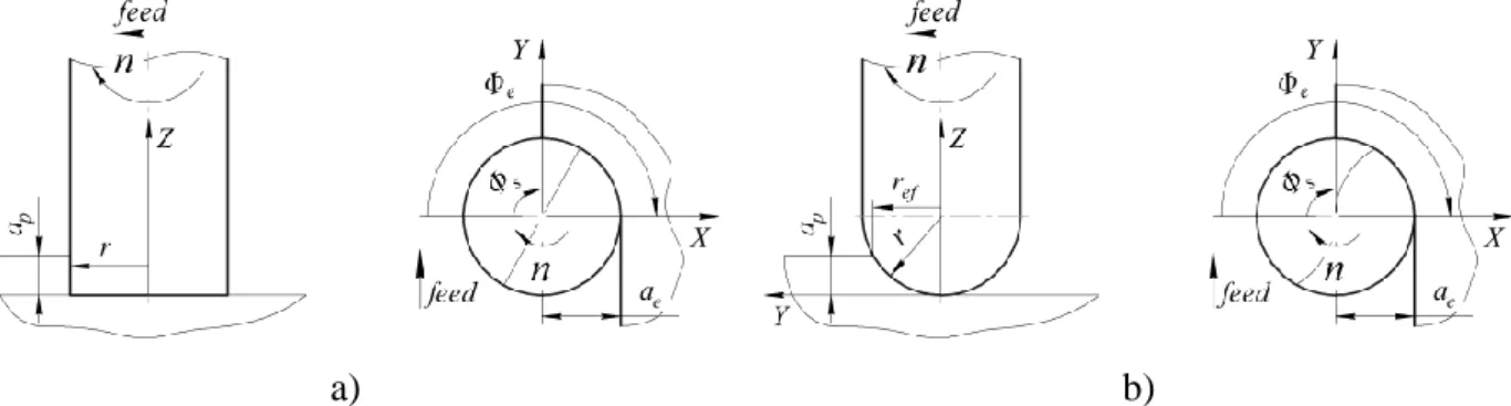
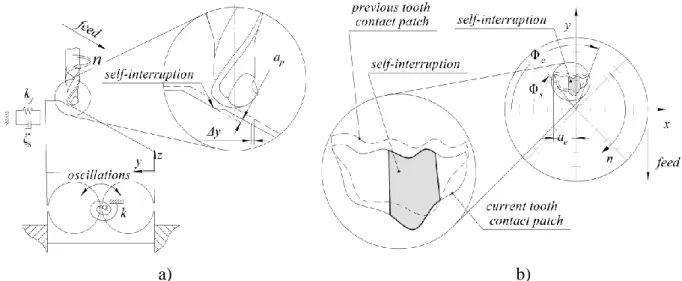
During point milling of planar surface with flat-end mill or ball-end mill start angle ϕ𝑠 always equals 0 for up-milling and π — for down-milling. The case of down-milling is shown on a Fig. 1 with flat-end mill (a) and ball-end mill (b), respectively.
a) b)
Fig. 1 Down-milling of planar surface with flat-end mill (a) and ball-end mill (b)
In this case start angle depends only on the value of variable radial depth of cut 𝑎𝑒 with the following equation: ϕ𝑠 = π − arccos(𝑟 − 𝑎𝑒). In the case of up-milling exit angle may be determined as a function of 𝑎𝑒 as: ϕ𝑒 = π + arccos(𝑟 − 𝑎𝑒). Cutting velocity is various in the case of ball-end milling and depends on effective radius value 𝑟𝑒𝑓.
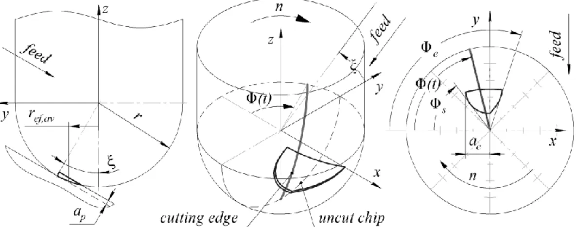
During copy milling of warped (sculptured) surface with ball-end mill the machining of different areas of this surface may be approximate analyzed as machining of number of inclined surfaces with different values of inclination angle. The inclination angle is identical to the lead angle ξ as the angle between cutter axis and surface normal.
The angle of contact between the tooth cutting edge of ball-end mill and the uncut chip is various in the case of copy milling of warped surface, and it depends on the values of depth of cut 𝑎𝑝,
radial depth of cut 𝑎𝑒, lead angle ξ, radius of the tool 𝑟 (Fig. 2).
Fig. 2 Downward up-milling of inclined surface with ball-end mill
Its value results as a difference of exit angle ϕ𝑒 and start angle ϕ𝑠, which may be determined from equations (1) for upward milling, (2) for upward down-milling, (3) for downward up-milling and (4) for downward down-up-milling (Shtehin, 2014).
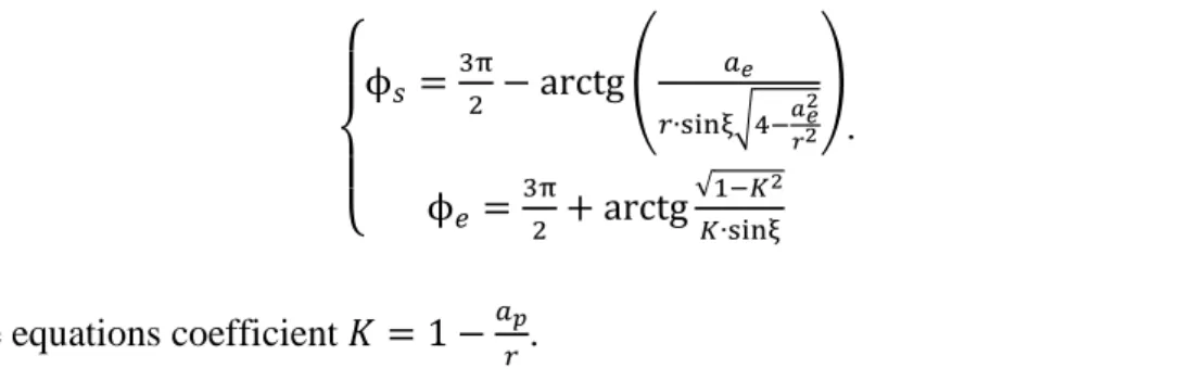
{ ϕ𝑠 =π2− arctg√1−𝐾𝐾∙sinξ2 ϕ𝑒 = π2+ arctg ( 𝑎𝑒 𝑟∙sinξ√4−𝑎𝑒2 𝑟2 ); (1) { ϕ𝑠 =π2− arctg ( 𝑎𝑒 𝑟∙sinξ√4−𝑎𝑒2 𝑟2 ) ϕ𝑒 =π2+ arctg√1−𝐾 2 𝐾∙sinξ ; (2) { ϕ𝑠 =3π2 − arctg√1−𝐾𝐾∙sinξ2 ϕ𝑒 = 3π2 + arctg ( 𝑎𝑒 𝑟∙sinξ√4−𝑎𝑒2 𝑟2 ); (3)
{ ϕ𝑠 = 3π2 − arctg ( 𝑎𝑒 𝑟∙sinξ√4−𝑎𝑒2𝑟2 ) ϕ𝑒 =3π2 + arctg√1−𝐾𝐾∙sinξ2 . (4)
In these equations coefficient 𝐾 = 1 −𝑎𝑝
𝑟.
Thus, contact patch is variable for every area of machining surface with dissimilar value of lead angle ξ.
Cutting force components
There is an essential difference between total cutting force 𝑓𝑐 and its components for different
machining conditions of warped surface ball-end milling. When lead angle is changing, values redistribution in a pair of radial and axial components occurs, even if its absolute value is the same for a constant depth of cut 𝑎𝑝. Normally radial component 𝐹𝑟 increases and axial
component 𝐹𝑎 decreases during lead angle increasing, as it is shown on a Fig. 3.
Fig. 3 Radial and axial cutting force components changing during lead angle increasing
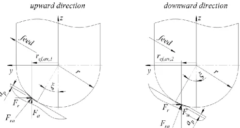
Tangential component 𝐹𝑡 is usually dominant in a total cutting force value. Effective average cutting velocity, which is a function of lead angle, substantially effects on it. Machining direction — upward or downward — also has a material effect on each cutting force component. The effective average radius of the tool 𝑟𝑒𝑓,𝑎𝑣 is difference for the same ξ (Fig. 4).
Fig. 4 Radial and axial cutting force components changing depending on machining direction
Total cutting force 𝑓𝑐 and instantaneous tangential, radial and axial cutting force components may be obtained from measured 𝐹𝑥(𝑡), 𝐹𝑦(𝑡) and 𝐹𝑧(𝑡) cutting force components with the next equation: 𝑓𝑐(𝑡) = { 𝐹𝑡(𝑡) 𝐹𝑟(𝑡) 𝐹𝑎(𝑡) } = [
sinϕ(𝑡)cosψℎ𝑙 cosϕ(𝑡)cosψℎ𝑙 −sinψℎ𝑙
−cosϕ(𝑡) sinϕ(𝑡) 0 sinϕ(𝑡)sinψℎ𝑙 cosϕ(𝑡)sinψℎ𝑙 cosψℎ𝑙
] { 𝐹𝑥(𝑡) 𝐹𝑦(𝑡)
𝐹𝑧(𝑡)
}; (5)
In Eq. (5) ψℎ𝑙 is a helix angle of cutter. Dynamic model
Schematically the single-degree-of-freedom (SDOF) system during ball-end milling is shown on a Fig. 5. The equation of oscillation of SDOF-system in a cut direction 𝑦 is:
{𝑦̈(𝑡) + 2ζ𝑠ω𝑛𝑦̇(𝑡) + 𝑑(𝑦̇) + ω𝑛2𝑦(𝑡) =
𝐹𝑦(𝑡)
𝑚 , 𝑤ℎ𝑒𝑛 𝑓𝑜𝑟𝑐𝑒 𝑖𝑠 𝑎𝑐𝑡𝑖𝑛𝑔
𝑦̈(𝑡) + 2ζ𝑠ω𝑛𝑦̇(𝑡) + ω𝑛2𝑦(𝑡) = 0, 𝑤ℎ𝑒𝑛 𝑓𝑜𝑟𝑐𝑒 𝑖𝑠𝑛′𝑡 𝑎𝑐𝑡𝑖𝑛𝑔 (𝑓𝑟𝑒𝑒)
; (6)
where 𝐹𝑦(𝑡) — cutting force in the 𝑦 direction; 𝑚 — modal mass; ω𝑛 — natural modal radial frequency; ζ𝑠 — natural modal structural damping ratio; 𝑦(𝑡) — instantaneous perturbation; 𝑑(𝑦̇) — general nonlinear damping. Modal stiffness 𝑘𝑧 along the axis 𝑧 may be neglected, so
𝑘 ≈ 𝑘𝑦.
The equation of motion of SDOF-system Eq. (6) has two different representations when cutting and when non-cutting. When tooth slices into uncut chip, the total cutting force 𝑓𝑐 starts acting. Its nature is quite complex, so total cutting force in fact has linear and nonlinear components.
Usually nonlinear component may be neglected because of its irrelevant effect on the technological system.
a) b)
Fig. 5 Single-degree-of-freedom system during ball-end milling: a) oscillation model; b) self-interruption area
The system oscillations start as forced oscillations, caused by primary impact, and then instantly go to the steady state of oscillations, sustained by inner friction of the system. These self-oscillations are damped and have linear (structural) and nonlinear damping components 𝑑(𝑦̇) = [𝑦̇(𝑡)]𝑝. Self-interruption condition is: ∆𝑦 ≥ 𝑎𝑝
sinξ.
When tooth disengages workpiece, system goes to the state of free damped oscillations. These oscillations are generated with disengaging (an impact). They have only linear (structural) damping component.
In accordance with the classical approach of stability analysis in machining the system loses its stability at frequency values close to the natural frequency of the system. However, in the case of low immersion milling, which is typical for ball-end machining, stability loss may take place at lower frequencies. It is a case of period-doubling bifurcation, when system oscillates with tooth pass frequency: 𝑓𝑇.𝑃.;12𝑓𝑇.𝑃., … — also called flip bifurcation.
EXPERIMENTAL SETUP
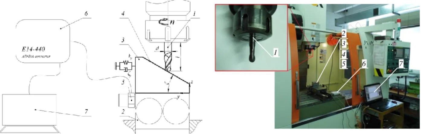
For understanding of mechanics of chatter genesis in the warped surface ball-end milling with small radial immersion it has been performed a number of tests with variable depth of cut, lead angle and spindle speed values. The experiments were carried out for upward down-milling (approximate the most preferable case) and for downward up-milling on CNC milling machine Victor VCenter-85. The experimental setup is shown on a Fig. 6. It includes solid carbide
ball-end mill Ø8 mm (1) with two flutes, flexible in the 𝑦 direction base plate (2) with the workpiece (3) on its top made of AISI 1045 Steel with inclined surface (4). On the back side of this plate the vibration sensor DN-4-M1 (piezoelectric accelerometer with a range up to 12.4 kHz) is attached (5). Its axis is parallel to the Y-axis of CNC milling machine. Signal from the sensor is converted with AD/DC-converter L-Card E14-440 (6) and analyzed on a PC (7) using MATLAB software. The sample rate was 10 kHz.
Fig. 6 The experimental setup for low-frequency chatter examining
To maintain the experimental integrity on each inclined surface the valleys of necessary depth were machined before. It made possible to provide machining with a pure up-milling and down-milling.
It was found that the dominant mode of the SDOF-system has natural frequency 𝑓𝑛 = 1542 𝐻𝑧 (period of oscillation equals ~6.5·10-4 s). Dynamic parameters of the SDOF-system are presented
in a Table 1.
Table 1
Dynamic parameters of the SDOF-system Parameter Value
Natural frequency 𝑓𝑛 1542 Hz Modal stiffness 𝑘𝑦 12.1 ·106 N/m Modal damping ζ𝑠 2.75 %
A number of tests were carried out with five values of lead angle: ξ = [22.5°; 30°; 37.5°; 45°; 52.5°]. Tests with lead angle values less than 22.5° were not taken into
account because of too small effective cutting velocity values.
1 6 1 7 4 3 5 2
Cutting has been performed with spindle speed values in a range from 5852 rpm to 8008 rpm. It made possible to maintain effective cutting velocity in a wide range — from 50 m/min (when ξ = 22.5°) to 160 m/min (when ξ = 52.5°).
Depth of cut (radial allowance) was in a range from 0.10 mm to 0.50 mm. Radial depth of cut was calculated for each test as 𝑎𝑒= 𝑟√1 − 𝐾2. Feed-per-tooth value was constant for all tests
𝑓𝑧 = 0.10 𝑚𝑚.
Surface roughness was measured with a non-contact optical measurement machine Alicona InfiniteFocus in a cutting direction.
ANALYSIS AND DISCUSSION
Stability lobes validation
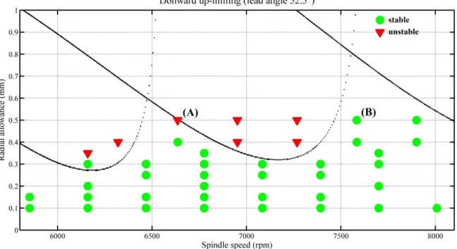
Fig. 7 Predicted stability lobes for downward up-milling with ξ = 52.5°
Stability lobe diagrams on a Fig. 7 were obtained for dynamic parameters presented in a Table 1. Tangential cutting force components were estimated for an orthogonal cutting during turning for the same pair of cutter and workpiece materials. Obtained values are consistent with the values determined earlier by Shtehin et al. (2017). Tangential cutting force component is linearly variable in general: 𝐾𝑡= 4000 𝑚𝑚𝑁2 when effective cutting velocity 𝑉𝑐,𝑒𝑓 = 95 𝑚𝑖𝑛𝑚 ; 𝐾𝑡 = 3500 𝑚𝑚𝑁2 when 𝑉𝑐,𝑒𝑓 = 108 𝑚𝑖𝑛𝑚 ; 𝐾𝑡= 3200 𝑚𝑚𝑁2 when 𝑉𝑐,𝑒𝑓 = 118 𝑚𝑖𝑛𝑚 . Radial cutting force component coefficient 𝑘𝑟 = 0.70 when ξ = 52.5° during downward milling. Point (A) is for 𝑛 =
6636 𝑟𝑝𝑚, point (B) is for 𝑛 = 7584 𝑟𝑝𝑚. Depth of cut is the same in the both cases: 𝑎𝑝 =
0.50 𝑚𝑚.
Detailed analysis
Analysis of these tests showed that downward up-milling is much less stable than upward down-milling. Spectral analysis of unstable cutting showed that stability loss takes place with frequency values close to 𝑓𝑇.𝑃.. For the determining of low-frequency chatter each registered signal was presented in a time-frequency domain, firstly. For these signals wavelet decomposition up to 6th level has been done, secondly. If there was a dominant harmonics close
to the 𝑓𝑇.𝑃. or aliquot to it in the spectrum of 5th and 6th decomposition levels, the conclusion of
low-frequency chatter presence have been done. Furthermore, such conclusion has been confirmed by the presence of vibrational trace on machined surface.
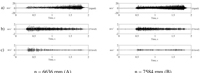
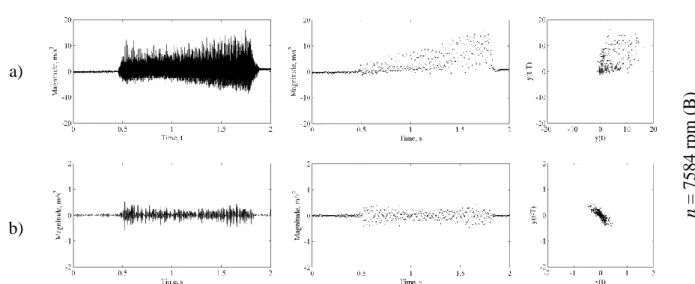
Two signals registered during downward up-milling of the surface with the angle of inclination ξ = 52.5° and depth of cut 𝑎
𝑝 = 0.50 𝑚𝑚 for two spindle speeds (6636 rpm and 7584 rpm) are
shown on a Fig. 8a. For the first test (𝑛 = 6636 𝑟𝑝𝑚) 𝑓𝑇.𝑃. = 221.2 𝐻𝑧 and for the second test (𝑛 = 7584 𝑟𝑝𝑚) 𝑓𝑇.𝑃. = 252.8 𝐻𝑧. In addition, 5th and 6th decomposition levels are presented
(respectively, Fig. 8b and Fig. 8c).
n = 6636 rpm (A) n = 7584 rpm (B)
Fig. 8 Experimental acceleration for downward up-milling with lead angle of 52.5° and depth of cut 0.50 mm for two spindle speeds (6636 rpm and 7584 rpm):
a) initial signal; b) 5 decomposition level; c) 6 decomposition level
Below the signals, there are respective 5th and 6th wavelet decomposition levels (mother wavelet is Daubechies wavelet db4). The 5th level corresponds with the tooth pass frequency, and the 6th level corresponds with every second tooth pass frequency (~12𝑓𝑇.𝑃.). If we compare signals and
a)
b)
respective decomposition levels on a Fig. 8, it is possible to make a conclusion, that the signals are almost the same, but low-frequency decompositions have visible difference.
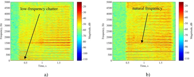
The same signals in a time-frequency domain are presented on a Fig. 9. It is noticeable, that in the first quarter of the signal (during about 0.5 s) on a Fig. 9a low-frequency chatter (𝑓𝑐 =
107 Hz ≈12𝑓𝑇.𝑃.) takes place and it vanishes subsequently. At the same time, low-frequency
chatter is almost absent, when spindle speed increases to 7584 rpm (Fig. 9b).
a) b)
Fig. 9 Experimental frequency evolution for downward up-milling with lead angle of 52.5° and depth of cut 0.50 mm: a) spindle speed n = 6636 rpm; b) spindle speed n = 7584 rpm
On a Fig. 9a oscillations with dominant frequencies close to a natural frequency take place when low-frequency chatter stops. At the same time, on a Fig. 9b oscillations with dominant natural frequency and period-doubling frequency 12𝑓𝑛 take place over much of the signal. It proves that machining process with 𝑛 = 7584 𝑟𝑝𝑚 is more stable and it is close to a steady state.
Poincaré section of these signals (Fig. 10a) and respective 6th decomposition levels (Fig. 10b) confirms, that low-frequency chatter occurs when 𝑛 = 6636 𝑟𝑝𝑚 and almost doesn’t occur when 𝑛 = 7584 𝑟𝑝𝑚. a) n = 6636 rpm ( A) natural frequency low-frequency chatter
b) a) n = 7584 rpm ( B ) b)
Fig. 10 Poincaré plots for downward up-milling with lead angle of 52.5° and depth of cut 0.50 mm for two spindle speeds (6636 rpm and 7584 rpm):
a) initial signal’s Poincaré plot; b) 6 decomposition level’s Poincaré plot
On a Fig. 11 machined surface photos and respective profile diagrams for downward up-milling with lead angle of 52.5° and depth of cut 0.50 mm for two spindle speeds (6636 rpm and 7584 rpm) are presented. Red rectangles which are placed on the initial signals (Fig. 11a), respective 6 decomposition levels (Fig. 11b), machined surface photos (Fig. 11c) and profile diagrams (Fig. 11d) show the areas of unstable cutting. It is noticeable, that low-frequency chatter has a very negative effect on machined surface.
Roughness measurement zones in [mm] (Fig. 11d) were obtained by feed-per-tooth (𝑓𝑧 =
0.10 𝑚𝑚) and spindle speed rotation values and compared with waveforms in [s] (Fig. 11a). In this way it has been found out that 20 mm length of machined surface conforms to 0.9 s in the case of 𝑛 = 6636 𝑟𝑝𝑚 and it conforms to 0.8 s in the case of 𝑛 = 7584 𝑟𝑝𝑚.
n = 6636 rpm (A) n = 7584 rpm (B)
Fig. 11 Roughness of machined surface for downward up-milling with lead angle of 52.5° and depth of cut 0.50 mm for two spindle speeds (6636 rpm and 7584 rpm):
a) initial signal; b) 6 decomposition level; c) machined surface photo; d) machined surface roughness
Machined surface roughness measurements are shown on a Fig. 12 in the same scale of 𝑅𝑧 values. The length of machined surface equals 35 mm. In the case of machining with 𝑛 = 6636 𝑟𝑝𝑚 maximum roughness deviation 𝑅𝑚𝑎𝑥1= 42.8 𝜇𝑚 (Fig. 12a). The length of surface area with a large roughness is 16 mm. In the case of machining with 𝑛 = 7584 𝑟𝑝𝑚 maximum roughness deviation 𝑅𝑚𝑎𝑥2 = 17.5 𝜇𝑚 (Fig. 12b). The length of surface area with a large roughness is 12 mm.
Fig. 12 Roughness of machined surface for downward up-milling with lead angle of 52.5°, depth of cut 0.50 mm and spindle speed:
a) 6636 rpm; b) 7584 rpm Discussion a) b) a) b) d) c) Rmax1=42.8 μm Rmax2=17.5 μm
Although 𝐹𝑟÷ 𝐹𝑎 ratio during downward milling is smaller than during upward milling, total cutting force may be greater in 2 times or more when downward milling because of substantially smaller effective cutting velocity. Because of it effective radial cutting force component is bigger during downward milling with the same lead angle value.
During downward up-milling tooth slices into uncut chip starting from zero chip thickness. Thus, contact stress between tooth cutting edge and uncut chip leads to deflection of the most non-rigid element of technological system without real shearing of uncut chip. While mill rotates uncut chip thickness increases. Therefore, shearing may occur suddenly. It leads to the leap of cutting force magnitude and its direction. Cutting tooth may even disengage workpiece before real cutting starts, especially if depth of cut is very small. Probably, genesis of low-frequency chatter has such nature.
While machining is in progress, oscillation energy is accumulated in the system, so the system goes to the steady state of parametric oscillation with a frequency value close to the natural frequency of the system.
Further research intends ascertain genesis of low-frequency chatter and its transition to the natural frequency vibrations (steady state).
CONCLUSIONS
In this paper the genesis of low-frequency chatter during warped surfaces machining with ball-end mills was investigated. More than two hundred cutting tests of inclined surface with different inclination angle, depth of cut and spindle speed rotation values were carried out. These tests showed, that low-frequency chatter has a very negative effect on machined surface, which gets worse, when angle of inclination growth in a range from 22.5° to 52.5°. However, this effect is
not so strong during down-milling in contrast with up-milling. It also was experimentally proved, that machining with downward direction is less stable than upward machining during the same depth of cut values.
Two cases of machining with angle value of 52.5° and depth of cut 0.50 mm were analyzed. In
the first case spindle speed was 6636 rpm and in the second case it was 7584 rpm. Low-frequency chatter took place in both cases. Roughness measurements showed that when spindle speed increased maximum roughness deviation Rmax decreased in 2.5 times — from 42.8 μm
(n = 6636 rpm) to 17.5 μm (n = 7584 rpm). The length of machined surface area with a large roughness became shorter — from 16 mm in the first case to 12 mm in the second case. Nevertheless, low-frequency chatter during downward up-milling does not take place during
machining with n = 6636 rpm and ap = 0.50 mm, when lead angle equals 37.5° and less due to
decreasing of radial cutting force component.
Clear low-frequency chatter analysis demanded vibration signal decomposition, that has been done by wavelet transform (mother wavelet was Daubechies wavelet db4). It made possible to analyze initial signals without high-frequency components, which have large magnitudes but immaterial effect on machining. Poincaré map of decomposed signals (6th decomposition level)
showed that just period-doubling of tooth pass frequency oscillation has a huge effect on machined surface.
The supposition, that the development of vibrations with low frequencies while magnitude is small is caused by sudden nature of shearing process have been made. This in turn leads to the leap of magnitude of cutting force and to the changing of its direction.
ACKNOWLEDGEMENTS
Authors wish to gratefully acknowledge METALLICADOUR — ASSAT (Tarbes, France) for the help in surface roughness measurements.
NOMENCLATURE
𝑎𝑒 radial depth of cut, mm
𝑎𝑝 depth of cut, mm 𝑓𝑐 total cutting force, N
𝑓𝑛 natural modal frequency, Hz
𝑓𝑇.𝑃. tooth pass frequency, Hz
𝐹𝑡, 𝐹𝑟, 𝐹𝑎 tangential, radial and axial cutting force components, N
𝐾𝑡 tangential cutting force component, N/mm2
𝑘𝑟 radial cutting force component coefficient, dimensionless 𝐾 = 1 −𝑎𝑝
𝑟 ball end mill indentation ratio (it characterizes the relation between depth of cut and ball end mill radius values), dimensionless
𝑘 modal stiffness, N/m 𝑚 modal mass, kg 𝑛 spindle speed, min-1 𝑟 ball end mill radius, mm
𝑟𝑒𝑓 effective radius of the cutting tool, mm
ζ𝑠 natural modal structural damping ratio, dimensionless
ξ lead angle, ˚ ϕ𝑠 start angle, ˚ ϕ𝑒 exit angle, ˚
ψℎ𝑙 helix angle of the cutter, ˚
ω𝑛 = 2π𝑓𝑛 natural modal radial frequency, s-1
REFERENCES
Altintaş, Y.; Budak, E. (1995) Analytical prediction of stability lobes in milling. CIRP Annals-Manufacturing Technology, 44 (1): 357–362.
Altintaş, Y.; Shamoto, E.; Lee, P.; Budak, E. (1999) Analytical prediction of stability lobes in ball end milling. Journal of Manufacturing Science and Engineering, 121 (4): 586–592.
Bayly, P. V.; Halley, J. E.; Mann, B. P.; Davies, M. A. (2003) Stability of interrupted cutting by temporal finite element analysis. Journal of Manufacturing Science and Engineering, 125 (2): 220–225.
Budak E. (2006a). Analytical models for high performance milling – Part I: cutting forces, structural deformations and tolerance integrity. International Journal of Machine Tools and Manufacture, 46 (12): 1478–1488.
Budak E. (2006b) Analytical models for high performance milling – Part II: process dynamics and stability. International Journal of Machine Tools and Manufacture, 46 (12): 1489–1499.
Butcher, E. A.; Bobrenkov, O. A.; Bueler, E.; Nindujarla, P. (2009) Analysis of milling stability by the Chebyshev collocation method: algorithm and optimal stable immersion levels. Journal of Computational and Nonlinear Dynamics, 4 (3): 031003–031003–12.
Campa, F. J.; de Lacalle, L. L.; Lamikiz, A.; Sanchez, J. A. (2007) Selection of cutting conditions for a stable milling of flexible parts with bull-nose end mills. Journal of Materials Processing Technology, 191 (1): 279–282.
Campomanes, M. L.; Altintaş, Y. (2003) An improved time domain simulation for dynamic
milling at small radial immersions. Journal of Manufacturing Science and
Engineering, 125 (3): 416–422.
Cao, H.; Lei, Y.; He, Z. (2013) Chatter identification in end milling process using wavelet packets and Hilbert–Huang transform. International Journal of Machine Tools and Manufacture, 69: 11–19.
Cao, H.; Zhou, K.; Chen, X. (2015) Chatter identification in end milling process based on EEMD and nonlinear dimensionless indicators. International Journal of Machine Tools and Manufacture, 92: 52–59.
Faassen, R. P.; Van de Wouw, N.; Nijmeijer, H.; Oosterling, J. A. (2007) An improved tool path model including periodic delay for chatter prediction in milling. Journal of Computational and Nonlinear Dynamics, 2 (2): 167–179.
Gradišek, J.; Govekar, E.; Grabec, I.; Kalveram, M.; Weinert, K.; Insperger, T.; Stépán, G. (2005) On stability prediction for low radial immersion milling. Machining Science and Technology, 9 (1): 117–130.
Insperger, T.; Mann, B. P.; Stépán, G.; Bayly, P. V. (2003a) Stability of up-milling and down-milling, part 1: alternative analytical methods. International Journal of Machine Tools and Manufacture, 43 (1): 25–34.
Insperger, T.; Stépán, G.; Bayly, P. V.; Mann, B. P. (2003b) Multiple chatter frequencies in milling processes. Journal of Sound and Vibration, 262 (2): 333–345.
Kim, S. J.; Lee, H. U.; Cho, D. W. (2007) Prediction of chatter in NC machining based on a dynamic cutting force model for ball end milling. International Journal of Machine Tools and Manufacture, 47 (12): 1827–1838.
Lamraoui, M.; Barakat, M.; Thomas, M.; El Badaoui, M. (2015) Chatter detection in milling machines by neural network classification and feature selection. Journal of Vibration and Control, 21 (7): 1251–1266.
Mann, B. P.; Insperger, T.; Bayly, P. V.; Stépán, G. (2003) Stability of up-milling and down-milling, part 2: experimental verification. International Journal of Machine Tools and Manufacture, 43 (1): 35–40.
Merdol, S. D.; Altintaş, Y. (2004) Multi frequency solution of chatter stability for low immersion milling. Journal of Manufacturing Science and Engineering, 126 (3): 459–466.
Mousseigne, M.; Landon, Y.; Séguy, S.; Dessein, G.; Redonnet, J. M. (2013) Predicting the dynamic behaviour of torus milling tools when climb milling using the stability lobes theory. International Journal of Machine Tools and Manufacture, 65: 47–57.
Séguy, S.; Insperger, T.; Arnaud, L.; Dessein, G.; Peigné, G. (2010) On the stability of high-speed milling with spindle high-speed variation. The International Journal of Advanced Manufacturing Technology, 48 (9-12): 883–895.
Shtehin, O. O. (2014) Vyznachennya kutiv vrizannya ta vykhodu pry obrobtsi pokhylykh poverkhon sferychnymy kintsevimi frezamy [Definition of start and exit angles in ball end milling of inclined surfaces]. Visnyk ZHDTU – Reporter of ZSTU, 3 (70): 62–67 [in Ukrainian]
Shtehin, O. O.; Wagner, V.; Séguy, S.; Landon, Y.; Dessein, G.; Mousseigne, M. (2017)
Stability of ball-end milling on warped surface: semi-analytical and experimental analysis. The International Journal of Advanced Manufacturing Technology, 89 (9–12): 2557–2569.
Stépán, G.; Szalai, R.; Insperger, T. (2004) Nonlinear Dynamics of High-Speed Milling Subjected to Regenerative Effect, in Nonlinear Dynamics of Production Systems (eds G. Radons and R. Neugebauer), Wiley-VCH Verlag GmbH & Co. KGaA, Weinheim, FRG: 111–128.
Sun, C.; Altintaş, Y. (2016) Chatter free tool orientations in 5-axis ball-end milling. International Journal of Machine Tools and Manufacture, 106: 89–97.
Tangjitsitcharoen, S. (2012) Analysis of chatter in ball end milling by wavelet transform. International Journal of Mechanical, Aerospace, Industrial, Mechatronic and Manufacturing Engineering, 6 (11), 2438–2444.
Tobias, S. A.; Fishwick, W. (1958) Theory of regenerative machine tool chatter. The Engineering, 205 (7): 199–203.
Wan, M.; Zhang, W. H.; Dang, J. W.; & Yang, Y. (2010). A unified stability prediction method for milling process with multiple delays. International Journal of Machine Tools and Manufacture, 50 (1): 29–41.
Wan, M.; Ma, Y. C.; Zhang, W. H.; & Yang, Y. (2015). Study on the construction mechanism of stability lobes in milling process with multiple modes. The International Journal of Advanced Manufacturing Technology, 79 (1–4): 589–603.
Yang, Y.; Zhang, W. H.; Ma, Y. C.; & Wan, M. (2016). Chatter prediction for the peripheral milling of thin-walled workpieces with curved surfaces. International Journal of Machine Tools and Manufacture, 109: 36–48.
Yao, Z. Q.; Liang, X. G.; Luo, L.; Hu, J. (2013) A chatter free calibration method for determining cutter runout and cutting force coefficients in ball-end milling. Journal of Materials Processing Technology, 213 (9): 1575–1587.
Yao, Z.; Mei, D.; Chen, Z. (2010) On-line chatter detection and identification based on wavelet and support vector machine. Journal of Materials Processing Technology, 210 (5): 713–719.
Zhang, X.; Zhang, J.; Pang, B.; Wu, D.; Zheng, X.; Zhao, W. (2016) An efficient approach for milling dynamics modeling and analysis with varying time delay and cutter runout effect. The International Journal of Advanced Manufacturing Technology, 87 (9–12): 3373–3388.
LIST OF FIGURES CAPTIONS
Fig. 2 Downward up-milling of inclined surface with ball-end mill
Fig. 3 Radial and axial cutting force components changing during lead angle increasing
Fig. 4 Radial and axial cutting force components changing depending on machining direction
Fig. 5 Single-degree-of-freedom system during ball-end milling: a) oscillation model; b) self-interruption area
Fig. 6 The experimental setup for low-frequency chatter examining
Fig. 7 Predicted stability lobes for downward up-milling with ξ = 52.5°
Fig. 8 Experimental acceleration for downward up-milling with lead angle of 52.5° and depth of cut 0.50 mm for two spindle speeds (6636 rpm and 7584 rpm): a) initial signal; b) 5 decomposition level; c) 6 decomposition level
Fig. 9 Experimental frequency evolution for downward up-milling with lead angle of 52.5° and depth of cut 0.50 mm: a) spindle speed n = 6636 rpm; b) spindle speed n = 7584 rpm
Fig. 10 Poincaré plots for downward up-milling with lead angle of 52.5° and depth of cut 0.50 mm for two spindle speeds (6636 rpm and 7584 rpm): a) initial signal’s Poincaré plot; b) 6 decomposition level’s Poincaré plot
Fig. 11 Roughness of machined surface for downward up-milling with lead angle of 52.5° and depth of cut 0.50 mm for two spindle speeds (6636 rpm and 7584 rpm): a) initial signal; b) 6 decomposition level; c) machined surface photo; d) machined surface roughness
Fig. 12 Roughness of machined surface for downward up-milling with lead angle of 52.5°, depth of cut 0.50 mm and spindle speed: a) 6636 rpm; b) 7584 rpm
LIST OF TABLES