HAL Id: hal-00111597
https://hal.archives-ouvertes.fr/hal-00111597
Submitted on 1 Mar 2019
HAL is a multi-disciplinary open access
archive for the deposit and dissemination of
sci-entific research documents, whether they are
pub-lished or not. The documents may come from
teaching and research institutions in France or
abroad, or from public or private research centers.
L’archive ouverte pluridisciplinaire HAL, est
destinée au dépôt et à la diffusion de documents
scientifiques de niveau recherche, publiés ou non,
émanant des établissements d’enseignement et de
recherche français ou étrangers, des laboratoires
publics ou privés.
Behaviour of a quasi-brittle material at high strain rate.
Experiment and modelling
Gérard Gary, Patrice Bailly
To cite this version:
Gérard Gary, Patrice Bailly. Behaviour of a quasi-brittle material at high strain rate. Experiment and
modelling. European Journal of Mechanics - A/Solids, Elsevier, 1998, 17, pp.403-420.
�10.1016/S0997-7538(98)80052-1�. �hal-00111597�
Behaviour of quasi .. brittle material at high strain rate.
Experiment and modelling
Gerard GARY *and Patrice BAILLY **
ABsTRAcr.- Strain-rate effects on the beha'<iour and on failure of concrete under quasi-static and dynamic loading (with uniaxial strain-rates up to 1000 s-1) are investigated from both experimental testing and modelling point of views. The main damaging process taken into account is
the brittle tensile response induced by Poissons' effects under compression loading.
The proposed meso-rnechanical model is based on a description of mechanisms observed at a microscopic level after failure has started. The strain-rate sensitivity then appears as a consequence of the motions of such mechanisms, with the introduction of the time derivative of the strain-rate
(€)
in the formulation. Dynamic loadings under compression are performed with a Split Hopkinson pressure bar (SHBP) apparatus. To investigate the response of concrete under multiaxial loading, a specific device presented in the paper is specially built toproduce dynamic compression under various controlled lateral confinement pressures, allowing for an independent evaluation of radial inertia and lateral pressure effects.
It is found that a small number of parameters, mostly deduced from a classical pure compression or traction test, allow for correct modelling of the response under multiaxial loading for a wide range of speeds of loading.
1. Introduction
In recent years, progress in computer technology and development of explicit codes (or hydrocodes) have made possible the calculation of the transient response of concrete structures under dynamic loading (earthquakes, collisions of cars, ships or planes with civil engineering structures). The need for constitutive laws taking account of strain-rate effects has given an impulse to experimental and theoretical investigations of the dynamic behaviour of concrete and other rock-like materials.
A rather significant literature exists on rate sensitivity of rock tested at medium strain rates, for example in previous papers (Cheatam,
1968;
Lindholmet al.,
1974),
(Christensenet al.,
1972)
and more recently (Klepaczkoet al.,
1991).
The early tests on concrete under dynamic loading have been performed with pendulum and dropweight tests. The lack of precision of these tests does not allow for an accurate determination of material behaviour, as shown in a review given by Green (Green,
1958).
The arrangement using an impulse loading in a cylindrical specimen made of concrete is used by Goldsmith and eo-workers (Goldsmithet al.,
1966)
to study the tensile fracture feature of concrete. Results obtained from different loading devices are compared and discussed by the state of the art report of the RILEM committee in1975
(RILEM,1975).
Application of the tensile SHPB arrangement to the concrete specimen has been reported by Reinhardt and eo-workers (Reinhardtet al.,
1986).
The use of the compressive SHPB to determine the rate sensitivity of concrete can be found in recent works (Gonget al.,
1990,
Tanget al.,
1972).
* Laboratoire de Mecanique des solides, Ecole Polytechnique, 91128 Palaiseau Cedex, France. ** Laboratoire Energetique Explosion Structure, Universite d'Orleans, 18020 Bourges Cedex, France.
Another type of dynamic test pe1formed on rocks is high strain-rate impulse loading, for example presented in
(Grady
&
Kipp, 1979; Forrestal et al., 1978). At those very high rates of loading(i
> 1000 s-1 ),
hydrodynamic models are often used and the deviatoric parts of the stress and strain tensors are disregarded.In this paper, we are looking at medium strain rates
(1
s-1 <i
<lOOos-1 )
.
In corresponding real loadings (collision of a car with a concrete civil structure for instance), the influence of deviatoric components of stress on the behaviour cannot be neglected. In this domain, as is generally the case for brittle materials, concrete shows an asymmetric ultimate behaviour (with a failure strength in tension much lower than in compression) under quasi-static loading and a strong sensitivity to the triaxiality of the loading (Cedolin et al., 1977). The same asymmetry is found for the strain-rate sensitivity, which, for concrete, remains small in traction (Reinhartet al., 1990) and strongly increases in compression (Tang et al., 1992).
Such an effect is often attributed to the lateral confinement induced by inertia effects (Klepaczko et al., 1991). It is thus important to take account of those effects in the physical analysis of the dynamic behaviour of concrete. Following the rather classical description of concrete plastic behaviour (Chen and Ting, 1980), one could use a global visco-plastic model to describe dynamic effects (Sluys and de Borst, 1992). One could also try to use methods closer to the physical microscopic behaviour (Rossi, 1994) but such methods cannot easily be introduced in classical computer codes. Using a mesa-mechanical approach, to allow for industrial efficiency by the introduction of the model in commercial explicit codes, and following (Bailly, 1994; Economou, 1995 and Reid, 1992), a model is proposed in which local inertia effects are introduced in the constitutive law through the strain acceleration
(i).
Checking the validity of this model needs a minimum of experimental results under dynamic multiaxial loading. Those results are obtained using a special device for dynamic tests on rocks under confined pressure, developed in one of the authors' Laboratories and presented in this paper.
2. The experiment
2. 1. THE SHPB DEVICE
The SHPB (Split Hopkinson Pressure Bar) system, also called Kolsky's apparatus is a commonly used experimental technique in the study of constitutive laws of materials at high strain rates. The first use of a long thin bar to measure stresses in impact conditions has been reported in (Hopkinson,
1914).
The experimental setting with two long bars widely used today is pioneered by Kolsky (Kolsky,1949).
This ingenious technique for a compression test has been extended to the tensile loading by Harding (Harding et al.,1960)
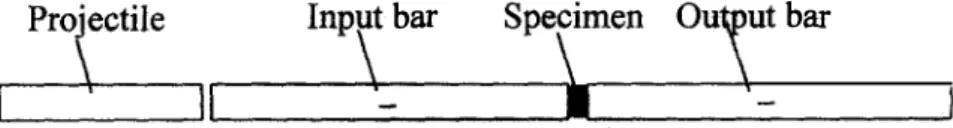
and to the torsional loading by Duffy (Duffy et al., 1971) with no significant changes in the concepts.A typical SHPB test system is shown in Figure
l.
It is composed ofthe
long input and output bars with a short specimen placed between them. With the impact of a projectile at the free end of the input bar, a compressive longitudinal "incident" wave eJ(t)
is created in the input bar. Once the incident wave reaches the interface specimen-bar, a reflected pulse eR(t)
in the input bar and a transmitted pulse eT(t)
in the output bar are developed. With gauges glued on the input and output bars, these three basic waves are recorded. TheirPro
,
ectile
lnp
\
t bar
Spe
\
imen
Ou�ut
bar
�--·--����---·---�•---·---�
treatment allows for the knowledge of forces and particle velocities at both faces of the specimen. Conditions of the homogeneity of mechanical fields in the specimen can
be
discussed depending on those measures.2.1.1.
Signal processingAccording to the wave propagation theory, stress and particle velocity associated with a wave are simply related to the strain measured by the gages. Thanks to the superposition principle and the shifting of waves (propagation theory), these values are known not only at the measured points but everywhere in the bar and in particular at bar-specimen interfaces.
Following Davies' and other authors works (Davies,
1948;
Malinowsky and Klepaczko,1986;
Malvern et al.,1991),
we use a complete data processing of the waves, including wave dispersion correction-recently extended to linear viscoelastic bars (Zhao and Gary,1995)-
and an assisted delay setting based on the elastic transient response of the specimen, (Gary et al.,1992,
Gary et al.,1993).
The use of that precise data processing is specially important for testing concrete (or brittle materials) that cannot support large strains without damage because it insures correct measurements at low strains (in the range of1%)
where rupture occurs and where the maximum stress is measured (Gary and Zhao,1996).
Forces and velocities at both sides of the specimen being known, assumptions for the specimen response must be chosen to obtain the constitutive law. The standard analysis assumes the homogeneity of strains in the specimen. In the case of concrete, transient simulations (Zhao,
1992;
Zhao et al.,1993;
Zhao and Gary,1995)
show that correct results are obtained using the so-called improved standard analysis-or three waves' analysis-using the average of the two forces to calculate the stress (Lindholm,1964).
The nominal values for average strain rate and stress applied to the specimen are, in that case, the following ones:(1), (2)
( t)
=Vlnput - Vouput
L.s
(t)
_
Flnput
+
Fouput
O's
'-2 Ss
where
Ls
andSs
are the initial length and section area of the specimen.The processing of the signals recorded with gauges is based on a one-dimensional description of the bar (even the dispersion correction, due to a 3D calculation, only takes account of the ID projection of those results on the bars' axes). Consequently, measurements at bar-specimen interfaces are integrated values: total force applied to the specimen, mean speed of its faces. A
3D
modelling of the specimen response is always possible but it needs additional assumptions for loading conditions.2.1.2.
Tests result analysis2.1.2.1.
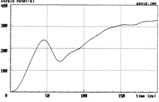
Non-constant strain-rateA typical average strain-rate for the specimen obtained with those assumptions is presented in Figure
2.
It would be convenient to fix the strain rate at a constant value in an idealised test, but this is obviously impossible (at least since the strain-rate equals zero at the beginning of the test). The assumption of a constant strain-rate is accepted when the rise time of the strain-rate is small compared with the duration of the test and when the strain-rate is almost constant during the test (as in quasi-static tests or approximately for some dynamic tests on metals). A different situation is shown in Figure2.
The strain rate is not constant for aSHPB
test on concrete and the measured stress-strain relation cannot be simply related to a constant value of the strain rate. In the following, when a nominal value of the strain-rate will have to be attached to a particular test, it will be chosen as the value associated with the maximum stress. Nevertheless, it mustbe
kept in mind that the response depends on the strain-rate evolution. This point is illustrated in Figure 3. Using a simulation withStrain rate(/s)
488
d.aU14
fitS181
. . ... ...r
. . ... . ...t
... . . . ... . . . ....:
.... . . . ... . .... ... . . 200 lOO strain rate (s'1) a b 0j
j
�
58
188
158
Fig. 2. -Average strain rate as a function of time.
I 0 strain (I 0'3) 200 100 stress (Mpa) 0
I
r ' bFig. 3. -Effect of strain-rate evolution on the global stress-strain relation.
(two simulations, using the behaviour modelled in section 3, with the same nominal value for the strain rate).
the model presented in the following: two different loadings with the same nominal value
of
the strain rate
produce close, but different, stress-strain responses.
2.1.2.2.
Contact conditionsExperimental problems found in concrete testing in compression have already been investigated by (Gorisse,
1982; Toutlemonde, 1994). They show, in particular, that fretting effects can induce an over estimated measure
of the
failure
strain. The influence of fretting conditions appears almost only in the post-peek response of the
specimen. In (Kotsovos, 1983), it is directly illustrated with constant length specimens and various fretting
conditions as in (van Mier, 1986) it indirectly appears
through
the effect of
the
specimen length.
Following
those authors it is found that the natural explanation of this effect is the presence of an undesired confined
loading induced by fretting effects near specimen ends.
Under dynamic compression, lateral inertia effects will become active as soon as lateral displacements appear
(this is one of the ideas introduced in the model proposed in this paper). If the additional lateral pressure
due to friction effects is the same as in a quasi-static loading, one can expect that it will be relatively less
important with respect to the finite overall lateral pressure induced by inertia. Furthermore, our main purpose is
to investigate the effects of lateral pressure and compare them to inertia effects. We are then always in loading
situations where a significant lateral pressure appears. An indication of less apparent fretting effects, is given in
a similar case, using bars with a Poisson's ratio close to the one of concrete: strain measurements with a strain
gauge glued on the specimen show results very close to the SHPB ones (Tang
et al.,1992).
2.1.2.3.
Specimen lengthPlatens used in our tests are the ends of 40
mmdiameter aluminium bars. Specimens have the same diameter
and length (40
mmdiameter, 40
mmlength). Considering contact condition, this length is rather small and it
is due to the dynamic loading conditions. The analysis of the test is based on the assumption of homogeneous
stress and strain fields. Consequently, the rise time .of the loading signal must be long compared to the
travelling time of the waves through the specimen therefore long specimens must be avoided. On the other
hand, the small-scale specimen tested, with a maximum aggregate size of 10 mm, would not have been correctly
represented with a shorter specimen.
A second point is that changing the specimen length could not be independent of changing the speed of
loading in order to keep the strain-rate constant. All the tests have been done with similar specimens.
2.2.
THE SPECIFIC DEVICE FOR CONFINED PRESSURE TESTSDifferent methods can be used to provide multiaxial loading conditions. A very simple one consists of making
oedometric tests. Such a method has given good results for sand testing (Semblat, 1994; Semblat
et al.,1995)
but cannot be easily applied to concrete because of unknown (and probably strong) longitudinal friction effects
induced by the differential strains betweeen the specimen and the thick confining cylinder.
To avoid longitudinal friction, another method exists using a thin metallic ring compressed with the specimen.
This method, used by Gong and Malvern (Malvern
et al.,1991) and others (Bragov
et al.,1994) needs a special
specimen preparation and the use of a strain-gage on the ring.
It
allows for a simultaneous measurement of the
radial pressure and strain of the specimen, but without the ability of an easy control of the lateral pressure.
For sake of simplicity, and following (Christensen
et al.,1972; Malvern
et al.,1991), the specimen is
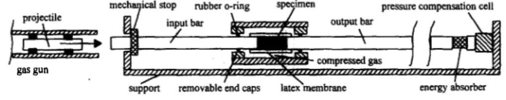
introduced into a cylindrical quasi-static pressure cell. The bars are acting as pistons and are introduced into
the cell through sealing rings. A scheme of the complete set-up is shown in Figure 4. The lateral pressure can
be applied with oil (up to 50 MPa), or with air (up to 10 MPa).
r"F"
gas gun2.2.1.
Sealing problems
Using a significant lateral pressure of oil
(20
MPa) a test without a specimen (bar against bar) has been performed to investigate the influence of seals on waves propagating in the bars. The complete data processing has been applied to the recorded incident and transmitted waves measured in this test. Input and output forces have been calculated. those forces, presented in Fig
ure5,
are not very different. This good agreement proves that the influence of seals can be disregarded.Force
OdU
1582.2.2.
Lateral pressure
Fig. 5. Input and output forces for a confined "bar against bar,. test
4
It seems reasonable to assume that a static confined pressure applied with air will not be significantly affected by the increase in the diameter of the specimen induced by the deformation (in this device, the chamber is
120
mm long and has a diameter of75
mm so that with a40
mm long and40
mm diameter specimen, the volume of the fluid in the chamber is almost10
times the volume of the specimen).The situation is not so clear with oil and it is not sure, because of transient effects in the fluid, that a measurement of the oil pressure during the test at a point in the chamber would give an exact measure of the pressure applied to the specimen. To evaluate this point, tests with oil and with air have been performed, using the same initial confinement pressure and other initial conditions. Results under oil pressure look very much like the ones presented in (Malvern
et al.,
1991)
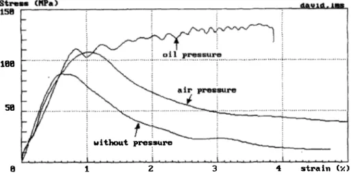
using a very similar device where water lateral pressure was used. When lateral pressure is applied with air, the stress strain relation shows a much lower apparent strain hardening, as presented in Figure6.
The same kind of results have been obtained in tests on sand specimens (Semblat,1994)
showing that oil pressure increases during the test. In that case, for similar tests (same specimen, same speed of loading, same initial lateral pressure), the stress associated with a given strain was minimum for air pressure tests, maximum for oedometric {zero lateral strain) tests, and in-between for oil pressure tests.Consequently, all the test results presented in the
following
to support our model, are obtained under a confined pressure of air, assumed constant duringthe
test and equal to the initial imposed and measured value.188
58
without pre
�
re8 1 z 3 4 strain (:;.)
Fig. 6. -Comparison between different lateral loading conditions.
3. Modelling of a quasi-brittle material
3.1.
BACKGROUND OF THE MODELLING3 . 1.1.
The general caseMany constitutive models to describe the macroscopic behaviour of concrete can be found in the literature
(Cedolin
et al.,1977; Chen and Ting, 1980; Bazant and Bhat, 1976; Bicanic and Zienkiewicz, 1983). Depending
on physical phenomenon observed in different situations, the non linear behaviour of a concrete-like material
is described by three different classes of models. The first class ("a") is associated with uniaxial loading or
loading with a small mean stress. The main physical behaviour involved is micro-cracking. The second class
("b") is associated with significantly multiaxial loading: the mechanical behaviour shows plastic flow. The third
class ("c") is associated with high pressure loading where significant compaction of the material occurs. When
this process is involved, the rate sensitivity is generally neglected, even at very high strain rates like those
found during impact producing shock waves.
For "c" -class models, the compacting process can be modelled by an "equation of state", i.e. a pure spherical
relation between the mean stress and the volumetric strain. When a plastic flow is observed ("b"-class), the
macroscopic behaviour is naturally modelled using a plastic or visco-plastic theory (Pietruszczaks
et al.,1988;
Chen
et al.,1975). Rather sophisticated models are found in this case, using for example a non associated
flow rule (Elwi
et al.,1979; Han
et al.,1985). The addition of a deviatoric behaviour, described by a plastic
model, and of a spherical behaviour has also been proposed (Mariotti
et al.,1994). Other authors associate
damage and plasticity theory (Ulm, 1993). In the case of general plastic behaviour, it is natural to introduce
the rate dependence with the visco-plastic theory (Suaris and Shah, 1984). The more sophisticated models
available for dynamic problems concern loading with medium or high pressures (Holmquist
et al.,1993) where
the sophistication is associated with a great number of parameters (to be identified).
Our approach is for "a" -class models. The micro-cracking can be introduced with damage theory (Mazars,
1984; Kachanov, 1980; Andrieux, 1986). Another approach is based on the study of mechanisms observed at a
microscopic level (Deng
et al.,1994; Kusano
N. et al.,1992). It should be expected that a constitutive law based
on such an approach needs a reduced number of parameters and that it will contribute to the understanding of
the physical response of the material. The rate sensitivity of the concrete and other semi-brittle material has for a long time been a subject for experimental investigations and theoretical modelling in this field.
In any case, when an apparent macroscopic rate sensitivity of the material is observed it raises the question whether it is due to a rheological material behaviour or is a simple consequence of the structural dynamic response of a finite volume dynamically loaded. In the latter case, especially when numerical finite elements' models are used-with elements, as they can be found in civil engineering, that are large compared with local mechanisms due to failure-, the question would remain of how to find a macroscopic rate-sensitive model. This question has already been widely discussed.
On the rheological
side, time dependent effects have been found. It has been proved that the crack velocity cannot exceed the speed of Rayleigh's waves (Bui, 1978; Deng et al., 1994 ). The presence of free water in the open porosity of the concrete could also explain a part of a rheological viscosity (Rossi, 1991 ). The opening of micro-cracks creates motion at a micro-level which could also induce inertial effects at the macro-level (Economou, 1995; Kusanov et al:, 1992).On the macroscopic
side,
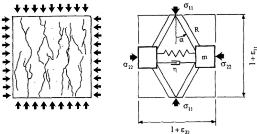
one could expect that a correct transient dynamic calculation of a concrete structure would be sufficient to describe the apparent rate sensitivity response. In recent works (Daudeville, 1996; Le Nard, 1996), it has been observed that a rate effect in the response of a cylindrical sample can be found, through a dynamic (including inertia effects) transient 3D calculation using a model that is not rate sensitive. Nevertheless, the agreement of such calculations with experimental results becomes better when the confining presure increases, showing that the rate sensitivity of a constitutive model is specially needed when lateral extension can occur, as it is the case when the confining pressure is closed to zero.One purpose of the present modelling work is to contribute to the understanding of the basic physical principles involved in the behaviour, using a micro-mechanical model with a small number of parameters. This model is then not intended to provide an exact mechanical description of a specimen in compression and our proposed comparisons between simulations and experiments are only a first step for a general qualification of basic ideas. The domain of validity investigated concerns loading paths of the structure leading to extensions in the material. In this case special attention is focused on the post-peak phase where failure in extension is under development. It is then expected that the response of our model and, in particular, the time sensitivity, will depend on inertia or viscous effects involved in the motion of basic mechanisms.
3.1.2. Construction of the model
In the construction of the model, the following observations concerning the general behaviour of concrete will be kept in mind:
-the damage criterion is a function of the strain in extension (Mazars, 1984), -effects of internal friction are observed in the fractured material (Attia, 1991),
-structural effects like buckling of the fractured material (Janach, 1979) and inertia of micro cracking (Klepaczko, 1988; Klepaczko, 1990) are involved in the dynamic behaviour.
The fractured material is described through a virtual continuum the behaviour of which includes structural effects. Those effects are obtained by introducing a mass in a rheological model, following previous authors (Economou, 1995; Bischoff and Perry, 1991). An analogical scheme, used as a rheologica1 model, is built in two dimensions, as shown in Figure 7.
This model is then to be used when there is at least one direction in extension producing cracks. Consequently, and as mentioned before, the behaviour under high pressure, as described in (Holmquist et al., 1993) is not investigated in this paper.
3.2.
RADIAL LOADING+++++++++
• • • .. .. .. .. .. .. + .....
Fig. 7. -Elementary volume of concrete and analogical rheological model.
c,J
+
The explicit formulation of the behaviour is deduced from the governing equations of the two�dimensional
mechanism. Those equations are written in the principal axes of the stress tensor. The first equation describes
the current state of the geometry of the mechanism (Fig. 7).
(3)
tga
=tgao
1
---+ c22
1
+ e:n
The second and the third ones describe the equilibrium of forces on the mechanism.
(4)
an
=R
(1
+en
1 )
cos
a
cosa
- cosao
(5)
o-22
== o-11tg a
+ a
f
( e22) + Pm i22 +
7J
l
og
(
i
:
02
)
Where the principal strains are named in increasing order
(en
<e22)-
R a stiffness,
Pm
an equivalent specific
mass and
7J
a viscosity coefficient.
a
is a geometric parameter
(ao
is relative to the virgin material) described in Figure 7.
In equation (5), the first term describes a buckling effect, the third an inertial one and the fourth a viscous
one. Function
Pt•
that appears in the second term, will influence the overall evolution of the response of the
model. This function describes an extension process and should depend only on the tensile behaviour of the
material.
Atensile behaviour has been experimentally measured, by (Terrien, 1980). It is described here by an
elastic model complete with damage and friction:
-if
e2m
< c:d<TJ
(.::22)
=E
e22
-if
e2m
> Cdwhere:
ed
is the strain limit of tension,
e2m
= max(e22)b,
is the maximum of the value of
e22
(t)
before the current time.
E
is classical Young's modulus.
When damage has occurred
(c:z
1112
c:d)
,
the term(J.f
is the result of two effects: crf, is a residual strengthafter cracking, for the most part due to bridging in the heterogeneous material, that
is
characterised by a damage parameter as written below, andrJfs is
a stress due to friction in the cracks. If the loading is tensile(cr11
0)the behaviour is directly governed by equation
(5 ).
(6)
(7)
where
<Jjp
=E
(1- �)
czz orafe
=E
(.!!i_)
nc:zz
with
1
< n< 2
C:zm
afs =(-van)/
1-
�d
)sign(izz)
(wbere(a) rnax(O, a))
\
C22
v is classical Poisson' s ratio,
.; is a damage parameter.
n is an empirical power law exponent.
It is important to note that, with such a model, the continuity of the stress is always verified with respect to time (or during the evolution), even when cracking occurs. When softening appears, the size of the strain localisation domain is a consequence of the effects of the equivalent specific mass and the viscosity coefficient in the equations of motion (de Borst,
1993; Zaki, 1995
andZaki, 1996).
For a small and reversible strain this model gives a response very close to classical linear elasticity. It is then easy to obtain relations between coefficients of the model and usual elastic constants:(8)
tgao
= vThe rate sensitivity introduced in
(5)
is associated with the opening of cracks in two different ways: First,r1
is a viscosity coefficient(io
is then a reference strain rate, for instanceio
= w-5/s) that will not play animportant role (see§
4.2.1).-
Second, the time dependence is related to an equivalent densityPm
that describes inertia effects associated with structural movements and a similarity can be found with the buckling of a column (Gary,1983).
This effect will be shown to dominate at high strain rates.This modelling approach can be extended to the
three
dimensional case when there is at least one principalstress in compression. The mechanism is then completed by the superimposition of a second (identical) one, chosen in a perpendicular plane, both planes being parallel to the compressive (loading) stress. Using the same analysis as in the single case
(20),
the model is described by the following equations:(9)
1
+
f:jitg ai
tg ao
---1 +
E"ll<Ju _
R
(
1
+
c:u _1
)
- IT cos ai IT cos ai
cos2 ao
ai
( )
..
I
(iii)
aii
= <Jll+a
f
i
€ii+Pm Eii + 71
og -;with
(i
(10)
2,
3
i -I- j)
O'fi (Eii)
=E (1- �i)
Eii+
(-vO'u)
\1- E�:)
sign
(i22)
with
�i
=1-
(
Ea
)
11and
Eim :::::rnax
(Eii )b
f1m
An important area for this kind of model is the explicit formulation of the behaviour which is suitable for a dynamic computation. In the case of a radial loading, the stress is given by equations depending on the strain, the strain rate, the strain acceleration and damage parameters
;;_ ::::
(
�i)
(11)
The thermodynamic consistency of the model is verified: the reversible energy is close to the one of a pure elastic material with actual moduli depending on damage parameters.
A
specific internal kinetic energy, Pbis
associated to inertial effects by:(12)
i
=2, 3
The dissipated power is due to damage, friction, and viscosity:
(13)
D =Z E
1
Eii
2 ·�
i
+
1. I
Eii
( l
TJ log io +
i
ii
l
(
) /
Ea
))
-vO'u
\1
-Eii
lts positiveness follows from the model construction.
3.3.
THE GENERAL CASE (NON-RADIAL LOADING)i
=2,
3
The model is simple to apply in the case of proportional loadings, frequently found in common dynamic loadings on real structures.
Its extension to general loadings is still theoretically possible (provided that the three principal strains are not in tension). Nevertheless, when the principal axis of the strain tensor varies during the loading, it becomes difficult to describe in a simple way the anisotropy of the damage and its evolution and it is necessary to introduce complementary assumptions. A simple criterion can be found to determine the first direction of the mechanism. For example, when the principal strain
E3,
which is an extension, reaches the limit Ea, it is assumed that the cracks of the corresponding elementary volume are orthogonal to the corresponding direction. One direction of the mechanism is then fixed. The determination of the second direction, chosen orthogonal to the first one, is not so natural. Furthermore, the axes of the mechanism become different to the principal axis of the strain tensor and complementary relations, not provided by the mechanism, are needed between stress and strain components. Following this kind of frame, a theoretical generalisation of the model has been proposed (Bailly,1994).
Knowing that dynamic test results under non radial loading are not generally available, such a generalisation is not developed in this paper.
4. Comparison of experimental results and theoretical predictions
4.1. STATIC TESTS
The parameters of the model are either directly deduced from a traction test, or indirectly derived from a
classical compression test. For the simulations presented in the following, the set of parameters below is used. It is deduced from a compression test.
E
= 32 1010 Pa,
V =0.2,
n1.57,
E:d =w-4.
stress
{Mpa)
&z
5
0
-5
Fig. 8. -Stress-strain relation for the simulation of a quasi-static compressive test.
The response of the model for a typical quasi-static loading is shown in Figure
8.
In that case, a constant low strain-rate of loading is applied(10-4
s-1) with no lateral pressure(o-2 =
0) The compressive strengthfc
is the maximum value of the axial stress (/c =65
MPa).
The behaviour obtained with the model presents theclassical phases of a compression test on concrete:
1.
o-1� 20 MPa (cz � cd),
the behaviour is close to linear elasticity.2.
o-1 >20 MP a
(!
!c),
damage appears and there is a non linear radial expansion but damageis
still not visible on the axial stress-strain curve. The volume change is still negative in this regionand·
becomes positive at abouto- = 0.
75
le·
3.
o-1
�fc,
a very high radial expansion is observed and the failure looks like an unstable phenomenon. The simulation of a confined compressive quasi-static test has been carried out (with the set of previously identified parameters). The triaxial test is divided in two phases: in the first phase, a hydrostatic pressure is applied(o-t
=o-2)
whi
eh
leads to aconfined
state(10 MPa);
in thesecond
phase adeviatoric
lo
ading
is appliedstress (Mpa)
---5
0
-5
Fig. 9. -Stress-strain relation for the simulation of a quasi-static confined compressive test.
(solid line: experiment, dotted line: simulation).
strength of which is about
65
MPa. The results of the simulation are compared with experimental ones in Figure9
showing a good agreement in the ultimate strength (which is about130
MPa).4.2. DYNAMIC COMPRESSION TESTS
The capability of the model to describe quasi-static tests under lateral pressure indicates that the proposed mechanism provides a good description of some bi-axial loading effects. A more important goal is nevertheless to have a model working in the dynamic range.
4.2.1.
Pure compression tests
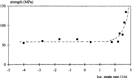
Many results found in the literature show an increase of the maximum stress with the average strain rate. Experimental results presented here have been obtained in a joint research program (Gary and Klepaczko,
1992)
on a large range of strain-rates, see Figure
10.
They show a change in the strain-rate sensitivity of the maximum stress, for a strain-rate about10
s-1, that could be due to inertial effects. Below this value, only a strain rate effect due to the viscosity may be visible. This viscous effect is small and is attributed to the presence of free water in the concrete (Rossi and Boulay,1990;
Rossi,1991).
For high strain rates(£ >100
s-1),
the structuraleffect is very important and becomes the major contribution to the apparent increase of the maximum strength. Parameters used in the model have already been identified with a quasi-static test except the specific mass
Pm·
This last value is now chosen to give the best fit with dry concrete test results. In the simulation, nominal strain-rate is that defined in section
2.1.
The maximum value of the stress as a function of strain-rate is shqwn in Figure10
and compared with experimental points.strength (MPa)
150
�---�100
50
I,
. . . ,..,. / -.----•--- -· ---- . .0 +---+---+---�----+---+---�----�--�
-5
-4 -3-2
-1
0
2
log. strain
rate(1/s)
Fig. 10.
-
The apparent compressive strength function of the strain rate(experimental data from Gary and Klepaczko. 1992).
3
4.2.2.
Dynamic compression tests under lateral pressureAll parameters used in the model are now fixed, a new loading condition is introduced with lateral pressure. The experimental device for confined dynamic compressive tests is described in section
2.
Simulations with the model are performed in the same way as for previous cases. An exampl
e of the axial stress-strain evolution is presented in Figure 11. The model provides a good evaluation of the maximum stress. The effect of the lateral pressure produces a post-peak residual stress which is also correctly described.150 100 50
stress (MPa)
---·--- ---·�--2 3 4 5 strain(1 o-2)
Fig. 1 1.
-
Stress-stmin relations for a confined dynamic compressive test. (solid line: experiment, dotted line: simulation) (confinement pressure= 5 MPa, nominal strain rate= 250 s-1 ).Figure
12
presents results at two different strain rates. Experimental results show that the strain rate has an influence on the maximum stress (apparent strength), as in the unconfined compression tests. It seems that the residual stress (post-peak phase) only depends on the confinement. The model provides good evaluations of those "apparent" and "residual" stresses. At high strain rates (i :;:::i600 s�1
)
, it produces oscillations in the softening phase of the stress-strain curve that are not observed in experimental results. This discrepancy could be due to transient effects in the specimen (propagation of waves through the specimen) which are neglected in the analysis of the test and are not introduced in the modelling. Indeed, stress and strain fields are assumed homogeneous in the model and the experimental average strain-rate used as input data is based on the same hypothesis. In the case of higher velocity impacts, very high strain rates can be locally produced that will not appear in the average strain rate history. The simulation of high velocity tests then requires a transient analysis of the specimen which is not developed in this paper.In Figure 13, the effect of the lateral pressure on the stress-strain curve is presented (with approximately the same axial strain rate for the different tests). The maximum stress and the "residual" stress both depend on the value of the pressure. The model correctly describes those effects.
stress (MP a) stress (Mpa)
150 r---,
108
50
Fig. 12. - Confined compressive test (left hand side) and simulation (right hand side). Influence of the strain rate (confinement pressure 5 MPa).
stress (MPa) stress (Mpa)
158 .---.
100
58
a
Fig. 13.
-
Confined compressive test (left hand side) and simulation (right hand side). fluence of the confinement (e 600 s-1 ) a, 0 MPa; b, 2.5 MPa; 5 MPa; d, 7 M5. Conclusion
Experimental results have been presented for concrete specimens under dynamic compression and quasi-static lateral loading. The original use of air pressure for lateral loading allows for a constant controlled value of this pressure during the test facilitating comparisons between experimental and theoretical results.
This model allows inertia effects to be taken into account by introducing the second time-derivative of the strain in the constitutive relation.
A
rather small number of parameters is needed so that an easy identification of the model is possible. It gives good agreement with experimental results in the dynamic range where it also correctly describes the effect of lateral pressure.Our purpose was to investigate the capability of taking account of inertia effects with the derivative of the strain rate and the model has been constructed to describe the behaviour of concrete when damage has already occurred. Dynamic results being mostly obtained under radial loadings, the use of such a model in a complex 3D loading situation will need further development.
Results presented here are obtained under the assumption of homogeneous stress and strain fields in the specimen, even in the dynamic range, as is commonly done in similar situations. Considering now the specimen as a structure itself, the same model has to be validated in the case of transient loadings. The measure of input and output forces and speeds at both ends of the specimen provides sufficient data to support such calculations (Rota, 1994). The transient simulation of the specimen response in which certain input conditions are prescribed (velocities for instance) provides calculated values of the other quantities (forces for instance) which can be compared with measured-or assumed-values. Results already obtained in this direction (Zaki, 1996) further validate the proposed model.
REFERENCES
ANDRIEUX S., BAMBERGER Y., MARIGO J. J., 1986, Un modele de materiau microfissure pour les betons et les roches, Journal de Mecanique Theorique et Appliquee, 5, n° 3, 471-513.
AITIA A. V., 1991, The Effect of Friction on Simulated Dynamic Fracturing of Rocks, Journal de Physique, colloque C3, 1, 745-750. BAILLY P., 1992, Modelisation des Essais de Compression Dynamiques, GRECO Geometrical scientific report, 97-100.
BAILLY P., 1994, Une modelisation d'un materiau fragile avec prise en compte d'effets dynamiques, Comptes Rendus de l'Academie des Sciences, Paris, 318, 727-732.
BAZANT Z. P., BHAT P. D., 1976, Endochronic Theory of Inelasticity and Failure of Concrete, Journal of the Engineering Mechanics Division, Vol. 102, No EM4, p. 701-722.
BICANIC, ZIENKIEWICZ, 1983, Constitutive model for concrete under dynamic loading, Earthquake Engineering and Structural Dynamics,
11, 689-710.
BISCHOFF P. H., PERRY S. H., 1991, Compressive Behaviour of Concrete at High Strain Rate, Materials and Structures, 24, 425-450. BRAGOV A. M., GRUSHEVSKY G. M., LOMUNOV A. K., 1994, Use of the Kolsky Method for Studying Shear Resistance of Soils, Dymat.
Journal, note, 3, 253-259.
BUI H. D., Mecanique de la rupture fragile, Masson, 1978.
CEDOLIN L., CRUTZEN Y. R. J., Pou S. D., 1977, Triaxial Stress-Strain Relationship for Concrete, Journal of the Engineering Mechanics Division, 103, 423-439.
CHEATAM J. B., 1968, The effect of pressure, temperature, and loading rate on the mechanical properties of rocks, Mechanical Behaviour of rock under Dynamic Loads, Springer, New York, 388-397.
CHEN A. C. T., CHEN W. F., 1975, Constitutive relations for concrete, Proceeding of the American Society of Civil Engineers, vol. 101, EM4, August.
CHEN W., TINGE. C.? 1980, Constitutive Models for Concrete Structures, Journal of the Engineering Mechanics Division, 106, 1-19. CHRIS TENSEN R. J., SWANSOW S. R., BROWN W. S., 1972, Split Hopkinson bar test on rock under confining pressure, Experimental Mechanics,
12, 508-541.
DAVIES R. M., 1948, A critical study of Hopkinson pressure bar, Philosophical Transactions of the Royal Society, A240, 375-457. de BORS T R., 1993, Fundamental issues in finite element analysis of localisation of deformation, Engineering Computations, 10, 99-122.
DENG H., NEMAT-NASSER S., 1994, Dynamic Damage Evolution of solids in compression: Microcracking, Plastic Flow, and Brittle-Ductile Transition, J. of Eng. Mat. and Technology, Trans ASME, 116, 268-289.
DUFFY J., CAMPBELL J. D., HAWLEY R. H., 1 97 1 , On the use of a torsional split Hopkinson bar to study rate effects in 1 100-0 aluminium, Journal of Applied Mechanics, 38, 83-9 1 .
ECONOMOU P., 1995, Evaluation of strain rate dependent model for concrete under tension applications, Material and Structure Modeling in Collision Research, Proceedings of the 9th Dymat technical conference, Munich, Germany, October 1995, Chapter 2.
ELWI A. A., MURRAY D. W., 1 979, A 3D hypoelastic concrete consitutive model, Journal of the Engineering Mechanics Division, vol. 105,
EM4, august.
FORRESTAL M. J., GRADY D. E., SCHULER K. W., 1978, An experimental method to estimate the dynamic fracture strenght of oil shale in the 103 to the 1 04 s-1 strain rate regime, lnternational lournal of Rock Mechanical Mining Sciences and Geomechanical Abstracts, 15, 263-274. GARY G., 1983, Dynamic Buckling of an Elastoplastic Column, International Journal of Impact Engineering, 1, 357-375.
GARY G., KLEPACZKO J. R., 1992, Essai de compression dynamique sur beton, GRECO Geomaterial scientific report, 105-1 18.
GARY G., KLEPACZKO J. R., ZHAO H., 1 992, Corrections for wave dispersion and analysis of small strains with Split Hopkinson Bar, Proceedings of "International Symposium of Impact Engineering ", Sendai', Japon, October 1992, 1, 73-78.
GARY G., KLEPACZKO J. R., ZHAO H., 1993, Application of microcomputers for Wave Dispersion Corrections for Split Hopkinson Pressure Bar, Proceedings of "ACMIRME'93 " International Symposium, Xian, Chine, 54-60.
GARY G., ZHAO H., 1 996, Measurements of the dynamic behaviour of concrete under impact loading, Proceedings of 2nd ISIE'96, Beijing, China, Chinese Journal Mechanics Press, 208-213.
GATUINGT F., DEAUDEVILLE L., 1 996, Simulation d'un essai dynamique avec un modele d'endommagement visqueux, Colloque "GEO ", Aussois, decembre.
GOLDSMITH W., POLIVKA M., YANG T., 1 966, Dynamic behaviour of concrete, Experimental Mechanics, 6, 65-79.
GONG J. C., MALVERN K. E., JENKINS D. A., 1990, Dispersion investigation in the split Hopkinson pressure bar, Journal of Engineering Material Technology, 112, 309-3 14.
GORISSE F., 1982, Les essais mecaniques, Le beton Hydraulique, Paris, Presses de l'Ecole Nationale des Ponts et Chaussees, 379-388. GRADY D. E., K!PP M. E., 1 979, Oil shale fracture and fragmentation at high rates of loading, Proceedings of the 20th U.S. Symposium on
Rock Machining, Austin, 1 19-127.
GREEN H., 1958. The impact testing of concrete, Mechanical properties of non-metallic brittle materials, Ed. Walton W. H., 300-317. HAN D. J., CHEN W. F., 1985, A non uniform hardening plasticity model for concrete materials, Mechanics of materials, 4, 283-302. HARDING J., WooD E. D., CAMPBELL J. D., 1 960, Tensile testing of materials at impact rate of strain, Journal of Mechanical Engineering
Sciences, 2, 88-96.
HOLMQUIST T. J., JOHNSON G. R., CooK W. H., 1993, A computational constitutive model for concrete subjected to large strains, high strain rates, and high pressure, Proceedings of the 14th International Symposium on Ballistics, Quebec, Canada, 26-29 Sept., 591 -600.
HOPKINSON B., 1 914, A Method of measuring the pressure in the deformation of high explosive by impact of bullets, Philosophical Transactions of the Royal Society of London, A213, 437-452.
JANACH W., 1 979, Impact of Steel Cylinder on a Rock Half-Space, The Institute of Physique Conference, 47, 3 3 1 -336.
KACHANOV M., 1980, Continuum model of medium with cracks, Journal of the Engineering Mechanics Division, vol. 106, EMS, october. KLEPACZKO J. R., 1988, On the Role of Microcracking Inertia in Rate Sensitivity of Coal at High Strain Rates, Archives of Mechanics,
Warszawa, 40, 345-358.
KLEPACZKO J. R., 1 990, Behavior of Rock-like Materials at High Strain Rate in Compression, International Journal of Plasticity, 6, 41 5-432. KLEPACZKO J. R., GARY G., BARBERIS P., 199 1 , Behaviour of rock salt in uniaxial compression at medium and high strain rates, Archives
of Mechanics, Warsawa, 43, 499-5 1 7 .
KOLSKY H., 1949, An investigation of mechanical properties of materials at very high rates of loading, Proceedings of the Physical Society London, B62, 676-700.
KOTsovos M. D., 1983, Effect of testing techniques on the post-ultimate behaviour of concrete in compression, Materiaux et Constructions,
91, 3-12.
KUSANO N. et al., 1 992, Impulse local damage analysis of concrete structure by the distinct element method, Nuclear Engineering and Design, 138, 105- 1 1 0.
LE NARD H., ROBIN B., BAILLY P., 1 996, Simulation de la compression dynamique de cylindres en beton, Colloque "GEO", Aussois, decembre. LINDHOLM U. S., 1964, Some experiments with the split Hopkinson pressure bar, Journal of Mechanics and Physics of Solids, 12, 3 1 7-335. LINDHOLM U. S., YEAKLEY L. M., NAGY A., 1 974, The dynamic strength and fracture properties of Dressel basalt, International Journal of
Rock Mechanical Mining Sciences and Geometrical Abstract., 11, 1 8 1 - 1 99.
MALINOWSKI J. Z., KLEPACZKO J. R., 1 986, A unified analytic and numerical approach to specimen behavior in the split Hopkinson pressure bar. International Journal of Mechanical Sciences, 28, 381-39 1 .
MALVERN L . E., JENKINDS D . A., TANG T., McLURE S., 199 1 , Dynamic testing of laterally confined concrete, Micromechanics of failure of quasi brittle materials, Elsevier Applied Science, 343-352.
MARIOm C., THOMAS F., 1994, Loi de comportement ARMOR pour geomateriaux sous sollicitation dynamique, Journal de Physique, IV,
MAZARS J., 1 984, Application de la mecanique de l'endommagement au comportement non lineaire et a la rupture du beton de structur�. These de Doctoral d'Etat es Sciences Phvsiques, Universite de Paris-VI, France.
VAN MIER J. G. M., Multiaxial strain-softening of concrete, Materiaux et Constructions, 111, 1 79-200.
PIETRUSZCZAKS, JLANG J., MJRZA F. A.. 1 988, An elastoplastic constitutive model for concrete, lnt. Joumal of' Solids and Structures, vol. 24,
0° 7, 705-722.
REm S. R., I 992, Response of wood and cellular structures to impact loading, Proceedings 11( "International Symposium of1mpact Engineering ... Sendai', Japon, October I 992, 2, 69 1 -698.
REINHARDT H. W., K6RMELING H. A., ZIELINSKI A. J.. 1 986, The split Hopkinson bar, a versatile tool for the impact testing of concrete,
Materiaux et Constructions, 19, 55-63.
REINHART H. W., Rossr P., Van MIER J. G., 1 990, Joint investigation of concrete at high rates of loading, Materials and Structures, 23, 2 1 3-2 16.
RILEM committee, 1 975. The effect of impact loading on building, Materiaux et Constructions, 8, 1 0 1 - 1 58.
Rossr P.. 1 99 1 , Influence of Cracking in the Presence of Free Water on the Mechanical Behaviour of Concrete, Magazine
11(
Concrete Research, 43, 53-57.Rossr P., 1 994, Dynamic behaviour of concrete: from the material to the structure, Materials and structures, 27, 3 1 9-323.
Rossr P., BoULAY C., 1 990, Influence of Free Water in Concrete on the Cracking Process, Magazine of Concrete Research, 42, 1 43- 1 46.
Rossr P., 1 99 I , Influence of the presence of free water in cracking on the mechanical behaviour of concrete, Magazine of Concrete Research. 43, n° 1 54, March, 53-57.
ROTA L., 1 994, An inverse approach for identification of dynamic constitutive equations, Proceedings
<!l
the second international symposium on inverse problems-ISIP'94/Paris!France, Inverse Problems in Engineering Mechanics, Bui, Tanaka et al., Balkema, Rotterdam.SANDLER I. S., Di MAGGIO F. L., BALAD! G. H., I 976, Generalised Cap model for geological materials, Journal of the Geotechnical
Engineering Division, vol. 1 02, GT7, july 1 976.
SEMBLAT J. F., 1 994, Sols sous sollicitations dynamiques et transitoires : reponse dynamique aux barres de Hopkinson, propagation d'ondes
en milieu centrifuge, These de Doctorat de l 'Ecole Polytechnique, Publication LCPC 1 995.
SEMBLAT J. F., GARY G., LUONG M. P., 1 995, Dynamic response of sand using 3D Hopkinson bar, Proceedings of IS-TOKY0 '95 First International Conference on Earthquake Geotechnical Engineering, Tokyo, November 1 995.
SLUYS L. J., de BoRST R., 1 992, Wave propagation and localisation in rate-dependent cracked medium-Model formulation and one-dimensional example. International Journal of Solids and Structures, 29, 2945-2958.
SUARIS W., SHAH S . , 1 984, Rate sensitive damage theory for brittle solids, Journal of Engineering Mechanics, 110, 985-997.
TANG T., MALVERN L. E., JENKINS D. A., 1 992, Rate effects in uniaxial dynamic compression of concrete, Journal of Engineering Mechanics, 1 18, 1 08- 1 24.
TERRIEN M., 1 980, Emission Acoustique et Comportement Mecanique Post Critique d'un Beton Sollicite en Traction, Bulletin de liaison de,,·
Ponts et Chaussees, 105, 65-72.
TouTLEMONDE F., 1 994, Resistance au choc des structures en beton, These de Doctorat, ENPC, Paris.
ULM F. 1.. 1 993, Un modele d'endommagement plastique : application au beton de structure, These de doctoral de I'Ecole Nationale des
Ponts et Chaussees.
ZHAO H., 1 992, Analyse de l'essai aux barres de Hopkinson, Application a la mesure du comportement dynamique des materiaux, These
de Doctoral, ENPC, Paris.
ZHAO H., GARY G., 1 995, A three dimensional analytical solution of the longitudinal wave propagation in an infinite l inear viscoelastic cylindrical bar. Application to experimental techniques. Journal of Mechanics and Physics of Solids, 43, 1 335-1 348.
ZHAO H., GARY G., 1 996, On the use of SHPB techniques to determine the dynamic behaviour of materials in the range of small strains, International Journal of Solids and Structures. Pergamon press, 33, 3363-3375.
ZHAO H., GARY G., ROTA L., 1 993, Utilisation de la barre de Hopkinson pour !'etude du comportement dynamique des materiaux fragiles,
I I' Congres Franr;ais de Mecanique, Lille-Villeneuve d' Ascq.
ZAKI L., 1 996, Reponse dynamique d'un milieu quasi-fragile. Modelisation et aspects mathematiques. Application a la compression et a la flexion du beton. These de Doctorat, Orleans University, France.
ZAKr L., BAILLY P., 1 995, Comportement dynamique de materiaux Quasi-fragiles, Actes du 12e Congres Franrais de Mecanique, Strasbourg,