HAL Id: hal-00960025
https://hal.archives-ouvertes.fr/hal-00960025
Submitted on 17 Mar 2014HAL is a multi-disciplinary open access
archive for the deposit and dissemination of sci-entific research documents, whether they are pub-lished or not. The documents may come from teaching and research institutions in France or abroad, or from public or private research centers.
L’archive ouverte pluridisciplinaire HAL, est destinée au dépôt et à la diffusion de documents scientifiques de niveau recherche, publiés ou non, émanant des établissements d’enseignement et de recherche français ou étrangers, des laboratoires publics ou privés.
Preliminary Design of Bilio-digestive Anastomosis by
Magnetic Compression.
M Courtaudiere, Nicolas Andreff, S. Koch
To cite this version:
M Courtaudiere, Nicolas Andreff, S. Koch. Preliminary Design of Bilio-digestive Anastomosis by Magnetic Compression.. 7th International Conference on Biomedical electronics and Devices, BIODE-VICES’14., Jan 2014, France. pp.218-223. �hal-00960025�
INTRODUCTION
Currently two treatments are available to treat a biliary obstruction. The first one is a non-invasive treatment: the ERCP (endoscopic retrograde cholangio pancreatography) using a duodenoscope and a guide wire through the obstruction allows to insert a biliary stent and thus to treat the obstruction However if the guide wire can’t be inserted through the tumor, the biliary stent cannot be placed and a cholangitis occurs and kills the patient. The second method is the invasive surgery to skirt the obstruction. For instance, duct-to-duct anastomosis by invasive surgery are performed. As a promising alternative to surgery, anastomosis by magnetic compression is currently practiced for intestinal anastomosis[1][2][3][4][5]. However, the reported
magnetic duct-to-duct compressions seem to require surgical insertion of the magnet placed upstream the obstruction (and may be also a surgical removal) [6].
Figure 1: Anatomic diagram of the gallbladder and the duodenum.
To avoid invasive surgery, the creation of an anastomosis by magnetic compression between the blocked bile duct and the duodenum could be the solution. However, the question of inserting a magnet in the bile duct upstream the obstruction without surgery is left unanswered yet.
Preliminary Design of Bilio-digestive Anastomosis
by Magnetic Compression
M. Courtaudiere1, N. Andreff2, S. Koch3
1Student at ISIFC, Université de Franche-Comté, Besançon, France 2 Femto ST Institute, UFC/CNRS/ENSMM/UTBM, Besançon, France
3 CHU J. Minjoz, Besançon, France
melanie.courtaudiere@edu.univ-fcomte.fr, nicolas.andreff@femto-st.fr, skoch@chu-besancon.fr
Keywords: Magnetic compression, bile duct, duodenum, ferrofluid, obstruction, jaundice.
Abstract: Some experiments have been realized to determine the characteristics of magnets allowing for bilio-digestive anastomosis by magnetic compression using a ferromagnetic gel and a magnet. The attraction distance between the ferromagnetic gel and the magnet was determined experimentally, under several configurations: magnet shape, strength, number and arrangements. Two magnets with a strength of 14 000 Gauss and a diameter of 12,7mm were necessary to attract 0,353mL of ferrofluid contained in a plastic sheath placed at 1cm of the mag -net. So the magnet is able to attract the ferrofluid. However, this procedure needs a large powerful magnet which is not compatible for an immediate use in the human body. Nevertheless, this preliminary result opens promising investigation paths.
Our proposal is to investigate the injection of a biocompatible ferromagnetic gel in the biliary duct and then study its attraction by the magnet placed in the duodenum.
Figure 2: Anatomic diagram of the biliary duct and the duodenum + obstruction and considered treatment.
METHOD
A novel clinical procedure
More precisely, the novel clinical protocol we foresee consists of the injection under EUS (endosonography) of a ferromagnetic gel by a FN with a diameter of 0.9mm (19G) above the obstruction of the bile duct. Then a magnet would be placed in the duodenum with a video endoscope. Removal of the magnet and gel would occur by simple natural elimination in the feces.
Anatomical constraints
Before this protocol can be tested, the choice of materials must be tested in accordance to the anatomical constraints.
Ideally, the magnet would be placed through the operator channel, thus limiting the diameter of the magnet to some 4.2 mm. Nevertheless, using a magnet with a somewhat larger diameter could be enabled by holding over the scope with a nylon wire
[8].
The common bile duct has an internal diameter included between 3mm and 8 mm in normal state (>10mm after cholecystectomy or in case of obstruction). The volume of ferromagnetic gel that needs to be considered must cope with the bile duct lumen.
The bile duct measures about 10cm (hepatic duct and common duct) and the anastomosis can be located only in front of the first duodenum. So the
distance between the gel and the duodenum magnet will be less than 1cm. Therefore, we need to determine the attraction strength of the magnets which are necessary to the attraction of a ferromagnetic gel localized at 1cm.
This is coherent with all the published studies, where the magnets were placed very close from one to another, with a maximal attraction distance between the magnets lower than 20mm. Moreover, the diameter of the different magnets varied between 2mm and 5mm. However, this does not tell much on how this would extend to bilio-digestive anastomosis. Indeed, replacing one magnet by ferromagnetic gel in order to avoid a surgical insertion in the bile duct completely changes the magnetic characteristics of the set-up.
The use of two kinds of magnets is reported: - magnets in Samarium-Cobalt - magnets in Neodymium-Iron-Bore
Both kinds are rare-earth magnets, identical in term of magnetic flow density. Each of them is appropriated for the anastomosis by magnetic compression but the obstructive strength of the magnets in Samarium-Cobalt is higher and so better. The magnets used in previous studies had a strength included between 3000 Gauss (~0.3 Tesla) and 3700 Gauss (~0.37 Tesla). Furthermore, to ensure their biocompatibility, many covering materials can be used, such as chromium, titanium nitride or polycarbonate. Different magnets shapes were used: spherical, cylindrical and ring-shaped. The spherical magnets show a smooth and round surface, thus they can move and roll up.
Experimental set-up and method
The experiments that were set-up consists of the use of off-the-shelf ferrofluid and magnets in various shapes, strengths and configurations.
A ferrofluid is a colloidal solution of ferromagnetic nanoparticles, having a size of 10nm, put in solution in a solvent or in water. The liquid becomes magnetic when an external magnetic field is applied however it keeps its stability colloidal. When the magnetic field is adequate, the ferrofluid is disheveled of points few rigid whose the topology varies in function of the parameters of the field. They are, most frequently, composed of nanoparticles of magnetite (Fe3O4) or of magnesite (γ-Fe2O3), which are both iron oxide. The ferrofluids have an application in many fields especially in medicine and biology (trying of biological groups, contrast substance, cancerology).
The magnets used were made in neodymium iron bore and had the following characteristics, determined thanks to the state of art:
Table 1: The different magnets used in the experiments Magnet Diameter (mm) Afterglow (Gauss) Magnetization Sphere 1 12,7 14 000 N42 Sphere 2 8 12 400 N38 Cylinder 1 5 13 500 N45
Sphere1 Sphere 2 Cylinder 1
Figure 3: Magnets used in the experiments.
The magnets were placed in 3 different configurations: horizontal, vertical and « loop » when it was possible. They were illustrated thereafter:
Figure 4: The 3 magnets in position horizontal.
Figure 5: The 3 magnets in position vertical.
Figure 6: The 3 magnets in position “loop”.
The magnets were used alone, by two or by three. Their simultaneous utilization was always made with magnets which had the same characteristics (there was no mix between the different types of magnets).
To measure the necessary distance for the attraction between the ferrofluid and the magnet, the following assembly was realized thanks to a gauge (Fig. 7). The gauge has a magnetic fixation system so the magnet(s) were simply fixed by magnetization.
Figure 7: Experimental set-up.
To represent the bile duct of the patient it was necessary to use a material which had the same characteristics as the human body. A plastic sheath possessed the matching properties. The ferromagnetic liquid was inserted with a syringe B-D Plastipak (capacity of 1mL) and a needle with a diameter of 0,45mm. The plastic sheath had a diameter of 3mm and a length of 5cm. The quantity of ferrofluid inserted was:
The needle was made of stainless steel which was not magnetic so there was not interaction with the ferrofluid.
Figure 8: Plastic sheath of 3mm filled with ferrofluid.
The experimental protocol was to place the sheath on the gauge base with the magnets far enough from it. Then, the magnets were slowly descended until the sheath was lifted up in the air by the magnetic attraction.
The acquisition of the movement was made by a camera Mikrotron EoSens 4 CXP with a 25mm
Computar objective. When the acquisition was finished, the attraction distance could be calculated. It corresponded at the distance between the base and the end of the plastic sheath, once it had been attracted by the magnet. The distance was directly legible on the screen thanks to the graduation of the gauge (Fig. 9).
Figure 9: Result of an acquisition.
To increase the reliability of the measures, each were realized 5 times, then the mean of the results was calculated.
RESULTS
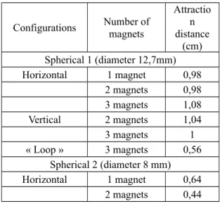
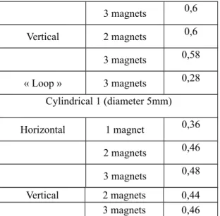
The results are assembled in the following table.
Table 2: The results of the experiments with the 3 magnets. Configurations Number of magnets Attractio n distance (cm) Spherical 1 (diameter 12,7mm) Horizontal 1 magnet 0,98 2 magnets 0,98 3 magnets 1,08 Vertical 2 magnets 1,04 3 magnets 1 « Loop » 3 magnets 0,56 Spherical 2 (diameter 8 mm) Horizontal 1 magnet 0,64 2 magnets 0,44
3 magnets 0,6 Vertical 2 magnets 0,6 3 magnets 0,58 « Loop » 3 magnets 0,28 Cylindrical 1 (diameter 5mm) Horizontal 1 magnet 0,36 2 magnets 0,46 3 magnets 0,48 Vertical 2 magnets 0,44 3 magnets 0,46
For a single spherical magnet, the horizontal and the vertical measure with one magnet is the same, so it appears only once in the table. The measures with the cylindrical magnets have been realized on the “short side”.
Figure 10: The two possible positions for the cylindrical magnets.
The difference of attraction between the horizontal and the vertical position for the same number of magnets was very low.
With the « loop » configuration the attraction length decreased of 50%. This configuration was not efficient, so it will be important to avoid this positioning for the magnets when they will be inserted in the human body.
For the same type of magnet, the attraction distance fluctuated in function of the number of magnet, sometimes the attraction distance is higher with 2 magnets than with 3. This fluctuation was caused by the positioning of the magnets one over the other.
Indeed the magnetization between them could be in different directions, thus it influenced the total properties of the magnet.
These results showed the variability of the attraction in function of the positioning of the magnets. When they will be inserted in the body it will be necessary to care of their orientation.
The utilization of several magnets increased the attraction distance. This increasing stays low. Moreover for the patient, the utilization of many magnets is not recommended for safety reasons (e.g. undesired magnetic compression in the small bowel), unless a specific device allows to keep them together.
DISCUSSION
The bile duct and the duodenum are separated by a distance of 1cm, so an attraction distance higher or equal is necessary. However, the weight of the sheath was measured to 1g, which means that the attraction force is only 10mN at 1cm distance. This might not be enough for starting the compression. Moreover, only the utilization of many spherical magnets with a diameter of 12.7mm and an afterglow of 14 000 Gauss (1.4 Tesla) allows to achieve this value. The diameter of such a magnet is not perfectly adapted for being used in the body because it is both heavy and yet still small enough to pass into the small bowel. The migration of this magnet should be avoided.
The alternative we will study now it the use of a set of weaker magnets (Fig. 11), attached together onto a muco-adhesive patch, in order to increase both the biocompatibility and efficiency of the device.
The patch would be inserted in the duodenum thanks to the operator channel of the endoscope, then it would be placed on the duodenum wall thanks to a self-expandable fully covered metallic stent.
To avoid the attraction of the magnets when the patch is in the operator canal and to allow its extension, the magnets should be oriented in the same direction of polarity (all the north faces are on the same side). To permit the adhesion of the patch on the duodenum wall, the patch could be covered with a muco-adhesive film.
Finally, the ferrofluid could be replaced by a magneto-rheologic fluid. Such fluids are made of lager ferromagnetic particles and thus have better magnetic properties. They are considered to have the drawback of sedimenting, contrary to ferrofluids where nanoparticles stay apart. Nevertheless, this might not necessarily be a concern in our case, if properly handled, because it would improve the removal of all magnetic material from the body at the end of the treatment.
ACKNOWLEDGEMENTS
This work was partly supported by the French ANR Labex ACTION (contract ”ANR-11-LABX-01-01”).
REFERENCES
[1] Uygun, I., Hanifi Okur, M., Cimen, H., Keles, A., Yalcin, O., Ozturk, H., Otcu, S., 2012. Magnetic compression gastrostomy in the rat in PEDIATR SURG INT.
[2] Pichakron, K., Jelin, E., Hirose, S., Curran, P., Jamshidi, R., Stephenson, J., Fechter, R., Strange, M., Harrison, M., 2011. Magnamosis II: Magnetic Compression Anastomosis for Minimally Invasive Gastrojejunostomy and Jejunojejunostomy in ELSEVIER.
[3] Gonzales, D., Douglas, G., Pichakron, K., Kwiat, D., Gallardo, S., Encinas, J., Hirose, S., Harrison, M., 2012. Magnamosis III: delivery of a magnetic compression anastomosis device using minimally invasive endoscopic techniques in JOURNAL OF PEDIATRIC SURGERY.
[4]Mimuro, A., Tsuchida, A., Yamanouchi, E., Itoi, T., Ozawa, T., Ikeda, T., Nakamura, R., Koyanagi,
Y., Nakamura, K., 2003. A novel technique of magnetic compression anastomosis for severe biliary stenosis in GASTROINTESTINAL ENDOSCOPY. [5] Itoi, T., Yamanouchi, E., Ikeuchi, N., Kasuya, K., Iwamoto, H., Tsuchida, A., 2010. Magnetic
Compression Duct-to-duct Anastomosis for Biliary Obstruction in a Patient with Living Donor Liver Transplantation in GUT AND LIVER.
[6] Fan, C., Ma, J., Zhang, H., Gao,R., Li, J. Yu, L., Wu, Z., Lv, Y., 2011. Sutureless Intestinal
Anastomosis with a Novel Device of Magnetic Compression Anastomosis in CHIN MED SCI.
[7] Itoi, T., Kasuya, K., Sofuni, A., Itokawa, F., Tsuchiya, T., Kurihara, T., Ikeuchi, N., Takeuchi, M., Nagano, T., Iwamoto, H., Yamanouchi, E., Shimazu, M., Tsuchida, A., 2010. Magnetic compression anastomosis for biliary obstruction: review and experience at Tokyo Medical University Hospital in HEPATO BILIARY PANCREAT SCI.