HAL Id: hal-02189909
https://hal.archives-ouvertes.fr/hal-02189909
Submitted on 20 Jul 2019
HAL is a multi-disciplinary open access
archive for the deposit and dissemination of
sci-entific research documents, whether they are
pub-lished or not. The documents may come from
teaching and research institutions in France or
abroad, or from public or private research centers.
L’archive ouverte pluridisciplinaire HAL, est
destinée au dépôt et à la diffusion de documents
scientifiques de niveau recherche, publiés ou non,
émanant des établissements d’enseignement et de
recherche français ou étrangers, des laboratoires
publics ou privés.
Interactive Cockpits Applications: Specification,
Prototyping and Validation using a Petri-nets based
Formalism
Arnaud Hamon, Célia Martinie, Philippe Palanque, Eric Barboni, David
Navarre, Adrienne Tankeu-Choitat
To cite this version:
Arnaud Hamon, Célia Martinie, Philippe Palanque, Eric Barboni, David Navarre, et al.. Interactive
Cockpits Applications: Specification, Prototyping and Validation using a Petri-nets based Formalism.
Embedded Real Time Software and Systems (ERTS2012), Feb 2012, Toulouse, France. �hal-02189909�
Interactive Cockpits Applications: Specification, Prototyping
and Validation using a Petri-nets based Formalism
Arnaud Hamon, Célia Martinie, Philippe Palanque, Eric Barboni, David Navarre, Adrienne
Tankeu-Choitat
ICS-IRIT
University Paul Sabatier (Toulouse 3),
118, route de Narbonne, 31062 Toulouse Cedex 4, France
{lastame}@irit.fr
ABSTRACT
The purpose of ARINC 661 specification is to define interfaces to a Cockpit Display System (CDS) which is used in many types of aircrafts cockpits such as A380 from Airbus, B787 from Boeing or Falcon 2000D from Dassault Aviation. ARINC 661 provides precise information for communication protocol between application (called User Applications) and user interface elementary components (called widgets). It also provides a detailed description of the widgets themselves (attributes, events …). However, in ARINC 661, very little information is given about the behaviour of these widgets and about the behaviour of an application made up of a set of such widgets. This paper presents a quick overview of the formal description technique called Interactive Cooperative Objects (ICOs) and its application for modelling the various elements of ARINC 661 specification. This formal description technique defines (in a precise and non-ambiguous way) all the elements of an interactive application compliant with ARINC 661 specification and especially their behavioural aspects which is definitively overlooked in the standard. The application of the formal description technique is shown on an interactive application to be used in an interactive cockpit. This application supports pilots’ activities while cooperating with Air Traffic Controllers (ATC) using a Data-Link (DL) communication technology. Such communication must follow a predefined protocol called CPDLC (Control-Pilot Data Link Communication). Using this application as a case study, we present how ICOs are used for modelling Interactive Widgets, User Applications and User Interface servers (in the ARINC 661 specification context). Lastly, we present briefly how such models can be exploited for verification and validation purposes of interactive cockpits applications.
Keywords
ARINC 661, Formal methods, Interactive Systems
INTRODUCTION
Interactive applications embedded in cockpits, is the current trend of evolution promoted by several aircraft manufacturer both in the field of civil and military systems (Faerber et al. 2000, Marrenbach & Kraiss 2000). With respect to technology currently deployed this evolution might be seen as a small step forward. Reality is very different. Embedding interactive application in civil and military cockpit is expected to provide significant benefits to the pilots by providing them with easier to use and more efficient applications increasing the communication bandwidth between pilots and systems. However, this technological enhancement comes along with
several problems that have to be taken into account with appropriate precautions. Questions such as: what kind of interactive components should be used in a cockpit? How to design such embedded interactive applications? What is the impact of such interaction techniques on the reliability of the application? What is the impact on the certification process? Such questions have been raised since the mid 90s and there is already an ongoing standardization process. ARINC specification 661 (see next section), aims at providing a common ground for building interactive applications in the field of aeronautical industry. However, this standard only deals with part of the issues raised. The aim of this paper is to propose a formal description technique to be used as a complement to ARINC 661 for the specification, design, implementation and validation of interactive application. The paper is structured as follows. Next section introduces ARINC 661 specification to define interfaces for a Cockpit Display System. It presents the content of the specification but also the parts that are left underspecified and that be dealt with precisely in order to build ARINC-661-compliant interactive applications. Section 3 presents the ICO formalism, a formal description technique for the design of safety critical interactive applications. This description technique has already been applied in the field of Air Traffic Control application. Its applicability to cockpit display system and its compatibility with ARINC specification 661 is presented in section 4 by means of a case study. This case study is used in the context of a ground-air data-link communication application embedded in the MCDU (Multifunction Control and Display Unit) equipment. Last section of the paper deals with conclusions and perspectives to this work.
ARINC 661
Purpose and Scope
The purpose of ARINC 661 specification (ARINC 661, 2002) is to define interfaces to a Cockpit Display System (CDS) used in all types of aircraft installations. Among the objectives of this standard we find:
• The minimization of the cost of adding new display function to the cockpit during the life of an aircraft.
• The introduction of interactivity in the cockpit, providing a basis to standardize the Human Machine Interface (HMI) in the cockpit.
ARINC 661 defines two interfaces between the CDS and the aircraft systems to provide a clear separation between them. The first interface is between the avionics equipment and the
display system graphics generators, and the second is a way to define the symbology and its related behavior. The CDS provides graphical and interactive services to user applications (UA) within the flight deck environment. A user application is then defined as a system that has a two way communication with the CDS:
• Transmission of data to the CDS, which can be displayed to the flight deck crew.
• Reception of input (as events) from interactive items managed by the CDS.
In the field of interactive systems engineering, interactive software architectures such as Seeheim (Pfaff 83) or Arch (Gram & Cockton 96) promote a separation of the interactive system in at least three components: presentation part (in charge of presenting information to and receiving input from the users), dialogue part (in charge of the behaviour of the system i.e. describing the available interface elements according to the current state of the application) and functional core (in charge of the non interactive functions of the system). The CDS part may be seen as the presentation part of the whole system, provided to crew members, and the set of UAs may be seen as the merge of both the dialogue and the functional core of this system. ARINC 661 dissociates, on one side, input and output devices (provided by avionics equipment manufacturers) and on the other side the user applications (designed by aircraft manufacturers). Consistency between these two parts is maintained through the communication protocol defined by ARINC specification 661. What may be found in ARINC specification 661 is:
• The definition of the software interface between the CDS and the UAs.
• The expression of airline desires in the form of guidance material. Designers should interpret this standard in terms of the “need” for specific design practices rather than practices that “must” be met under all circumstances.
What may not be found in ARINC 661 is:
• The specification the “look and feel” of any graphical information.
• The description of what must be done to design a CDS.
User Interface Components in ARINC 661
The communication between the CDS and UAs is based on the identification of user interface components hereafter called widgets. ARINC 661 defines a set of 42 widgets that belong to 6 categories. Widgets may be any combination of “container”, “graphical representation” of one or more data, “text string” representations, “interactive”, dedicated to “map management” or may “dynamically move”.
In ARINC 661, widgets are defined by: • one identifier,
• states classified in four levels (visibility, inner state, ability, visual representation),
• a description in six parts (definition section, parameters table, creation structure table, event structure table, run-time modifiable parameter table, specific sections).
The main drawback of this description is the lack of description of the behaviour itself. Even if states are partially described, dynamic aspects such as state changes are informally described.
As stated in ARINC 661, the main paradigm is here based on this observation:
“A UA should not have any direct access to the visual representations. Therefore, visual presentations do not have to be defined within the ARINC 661 interface protocol. Only the ARINC 661 parameter effects on graphical representation should be described in the ARINC 661 interface. The style guide defined by the OEM should describe the “look and feel” and thus, provide necessary information to UAs for their HMI interface design.”
That implies to clearly define the communication between objects (widgets and UAs), and clearly define the impact of state changes on the presentation of these objects.
As ARINC 661 is devoted to be used in aircraft cockpit, the certification problems are raised. Therefore our main contribution is to use an already existing formal description technique (ICO) to precisely raise ambiguities in ARINC 661.
ICO FORMALISM Informal Presentation
The aim of this section is to recalls the main features of the ICO (Interactive Cooperative Objects) formalism that we have proposed for the formal description of interactive system. The formalism will be used for the case studies and performance evaluation in the next sections. We encourage the interested reader to look at (Bastide et al., 95), (Bastide et al., 99) and (Navarre et al., 09) for a complete presentation of this formal description technique.
The Interactive Cooperative Objects (ICOs) formalism is a formal description technique dedicated to the specification of interactive systems (Bastide et al., 98). It uses concepts borrowed from the object-oriented approach (dynamic instantiation, classification, encapsulation, inheritance, client/server relationship) to describe the structural or static aspects of systems, and uses high-level Petri nets (Genrich, 91) to describe their dynamic or behavioural aspects.
ICOs are dedicated to the modeling and the implementation of event-driven interfaces, using several communicating objects to model the system, where both behaviour of objects and communication protocol between objects are described by Petri nets. The formalism made up with both the description technique for the communicating objects and the communication protocol is called the Cooperative Objects formalism (CO and its extension to CORBA COCE (Bastide et al., 2000)).
In the ICO formalism, an object is an entity featuring four components: a cooperative object with user services, a presentation part, and two functions (the activation function and the rendering function) that make the link between the cooperative object and the presentation part.
Cooperative Object (CO) part: a cooperative object models the behaviour of an ICO. It states how the object reacts to external stimuli according to its inner state. This behaviour, called the
Object Control Structure (ObCS) is described by means of high-level Petri net. A CO offers two kinds of services to its environment. The first one, described with CORBA-IDL (OMG, 98), concerns the services (in the programming language terminology) offered to other objects in the environment. The second one, called user services, provides a description of the elementary actions offered to a user, but for which availability depends on the internal state of the cooperative object.
Presentation part: the Presentation of an object states its external appearance. This Presentation is a structured set of widgets organized in a set of windows. Each widget may be a way to interact with the interactive system (user system interaction) and/or a way to display information from this interactive system (system user interaction).
Activation function: the user system interaction (inputs) only takes place through widgets. Each user action on a widget may trigger one of the ICO's user services. The relation between user services and widgets is fully stated by the activation function that associates to each couple (widget, user action) the user service to be triggered.
Rendering function: the system user interaction (outputs) aims at presenting to the user the state changes that occurs in the system. The rendering function maintains the consistency between the internal state of the system and its external appearance by reflecting system states changes.
ICOs are used to provide a formal description of the dynamic behaviour of an interactive application. An ICO specification fully describes the potential interactions that users may have with the application. The specification encompasses both the "input" aspects of the interaction (i.e. how user actions impact on the inner state of the application, and which actions are enabled at any given time) and its "output" aspects (i.e. when and how the application displays information to the user). An ICO specification is fully executable, which gives the possibility to prototype and test an application before it is fully implemented (Navarre et al. 2000). The specification can also be validated using analysis and proof tools developed within the Petri nets community and extended in order to take into account the specificities of the Petri net dialect used in the ICO formal description technique. This formal specification technique has already been applied in the field of Air Traffic Control interactive applications. A case study on this field can be found in (Navarre et al. 2002).
Using ICO in ARINC 661
As written in the description of ARINC 661, the need for precise specification occurs both at widget and UA levels. As shown in the case study (next section) ICO formal description technique can provide support for both levels.
At widget level, ICO must be used to describe the inner behaviour of the widgets and to describe the impact of state changes on their external presentation.
At user application level, ICO must be used to describe the behaviour of the application itself and the impact of state changes in term of widget parameters modification.
Next section shows the application of the formal description technique to a simple application compliant with ARINC 661.
CASE STUDY
In this section we focus on an application based on CPDLC (Controller-Pilot Data Link Communications) (ICAO, 91).
“Voice radio messages between pilots and air traffic controllers are exchanged continuously. The CPDLC system reduces the number of voice messages by using a special electronic link for routine messages. These messages are digitally displayed on a computer screen in the cockpit. Shifting routine transmissions from voice to data link communications frees up voice frequencies, reduces delays and potential misunderstandings”.
The application we propose to model allows the pilot to reply to clearances sent by the air traffic controller (ATC). The pilot may select a clearance and then provide an answer to that particular clearance. ICAO CPDLC provides precise syntax for communication between pilots and ATC. Indeed, depending on the type of the clearance sent, the possible answers are predefined. For instance:
• For a clearance of the type “CLIMB AND MAINTAIN FL330”, that means the pilot is requested to reach flight level 330, the possible answers are “WILCO”, if the pilot accepts the request or “UNABLE”, if he does not.
• For a clearance of the type “AT FL330 REPORT”, the pilot answers “ROGER” when the requested flight level is reached.
For space reasons we only present in this paper an application featuring few widgets and supporting few tasks. However, the specification covers the entire application both at the widgets and the User Application levels. As the User Application exploits information from the widgets, next section deals with the widget level.
Specification of widgets
In this section we first start by recalling the definition of widgets in ARINC 661 and then show how ICO can be fruitfully used to formally represent their detailed behaviour. As written in the section “Widgets in ARINC 661”, a widget is defined with an identifier (widget type, widget identifier and widget parent), states (informal description of the relationship between these states) and a six other description parts, detailed hereafter.
1. Definition section. This section provides general information on the widget such as the categories it belongs to, a functional description of its behaviour and restrictions (if any) with respect to ARINC 661 principles. For instance, the definition section of the ARINC 661 PushButton is:
Categories:
Graphical representation, Interactive, Text string.
Description:
A PushButton widget is a momentary switched button, which enables a crew member to launch an action. A PushButton has only one inner state, so there is no need for an inner state parameter.
Restriction:
None.
2. Parameters table. This table (not presented here for space reasons) provides the list of the widget parameters divided into
two categories (commonly used parameters and specific parameters).
Example of such parameters are: The X position of the widget reference position, Ability of the widget to be activated, …). 3. Creation structure table. This table (not presented here for space reasons) presents the parameters required for the instantiation of the widget crossed with their type, size and restrictions on value (if any).
4. Event structure table. This table presents the event notification structure (see Table 1 for the PushButton one). It
describes the parameters that may be hold by the events.
Event structure Size (bits) Value/Description
EventId 16 A661_EVT_SELECTION
Table 1 –PushButton event structure
5. Run-time modifiable parameter table. This table presents the sets of parameters that may be changed at run-time. Table 2
presents the runtime modifiable parameters table of the PushButton.
Parameter Type Size Parameter Ident Type of structure
Enable Uchar 8 A661_ENABLE …
Visible Uchar 8 A661_VISIBLE … LabelString String {32}+ A661_STRING … StyleSet Ushort 16 A661_STYLE_SET …
Table 2 –PushButton Runtime Modifiable Parameters
6. Specific sections. This section presents additional
information to complete the widget definition if necessary. This information may be additional type definition or dedicated data structures.
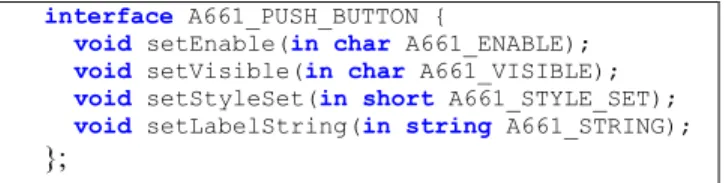
7. Additions to ARINC 661 description. The main drawback of this description is the lack of specification of state changes and their impact on the presentation of the widget. In order to be able to build reliable and certifiable interactive software a precise and unambiguous specification is required. We exploit here the ICO formal description technique presented above. As stated earlier, the behaviour of a widget is made up with a CORBA-IDL software interface, as shown by Figure 2, and a high-level Petri net, as shown in Figure 1.
interface A661_PUSH_BUTTON {
void setEnable(in char A661_ENABLE); void setVisible(in char A661_VISIBLE); void setStyleSet(in short A661_STYLE_SET); void setLabelString(in string A661_STRING);
};
Figure 2 - Corba-IDL software interface for ARINC 661 PushButton
The Corba-IDL software interface defines what services the concerned object provides. For the description of ARINC 661 widgets, this software interface defines the run-time modifiable parameters: one definition of a “set” method for one run-time modifiable parameter. For instance, the ARINC 661 PushButton provides a run-time modifiable parameter, called Enable of the type “char”, as shown by Table 2. In its
IDL definition, this parameter is represented by the method “void setEnable(in char A661_ENABLE)”.
In the High-level Petri net model in Figure 1 the complete and
unambiguous description of the widget is given. Places (depicted as ellipses) represent the state variables and the distribution of tokens (small grayed-out circles) in the places represent the current state of the model. State changes occur through the "firing" of transitions (depicted as rectangles) that
remove tokens from the input places and deposit tokens in the output. At firing time the values of tokens may be changed (according to the code of the transition). Widget parameters are held by tokens in places. Depending of the repartition and value of these tokens, special transitions (called synchronized transitions) may be fired, and when fired, these transitions raise an event (those described in the corresponding ARINC specification). Therefore, by specifying the widget behaviour, we clearly define the conditions under which a widget raises an event.
The second element of the ICO description is the definition of the activation and rendering functions in order to model the impact of state changes on the external presentation of the widget. Compliantly with ARINC 661, we do not describe here the “look and feel” of the widget, but show what must be represented. Indeed, the important element is what information has to be presented to the pilot and when to present it.
Table 3 shows an excerpt of the rendering method of the
PushButton. For instance, it describes that when a token enters the place Enabled, the PushButton must be shown as enabled.
ObCS Item Event Rendering method Place LabelString Token <x> enters Display <x> Place Enabled Token enters Show as enabled Place Enabled Token exit Show as disabled
Table 3 – Excerpt of PushButton rendering function Specification of the application
The application we focus on takes place in a MCDU
(Multifunction Control and Display Unit) as the one proposed by Thales Avionics (a high resolution 6in x 8in liquid crystal display). It is a one page application (see Figure 4 a) for
instance) dedicated to the handling of the ATC clearances. This application is made up with a ListBox that contains the clearances received, and 5 PushButtons (one to answer “WILCO” to the selected clearance, one for “UNABLE”, one for “ROGER”, one for “MONITOR” and one to request a voice contact). Figure 4 shows possible graphical
representation of this application, depending on crew actions.
(a)
(b)
Figure 4 - Possible graphical representation of the considered User Application: (a) no clearances are selected, (b) a clearance
type (wilco/unable) is selected
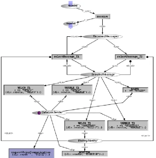
The main recommendation of ARINC 661 about User Application description is to respect the communication protocol between UAs and widgets. As described above, UA may only modify widgets through their parameters, and widgets impacts on UAs through the raising of events. The ICO behavioural description presented in Figure 3 goes beyond
by providing a complete description of the behaviour of such application while remaining compliant with ARINC 661 recommendations.
Figure 3 presents the behaviour of the considered User
Application, for which several synchronized transitions are linked to widgets. For instance, the transitions called
WILCO_T1 and WILCO_T2 (that represents the user service WILCO) will be fired when the event A661_EVT_SELECTION
from the PushButton Button_Wilco occurs. This relationship is described by the activation function presented in Table 4.
Widget Event Rendering Method User service List_Clearances A661_EVT_ SEL_ENTR Y_CHANGE setClearancesEnable selectMessage Button_Wilco A661_EVT8 SELECTION setBWilcoEnable WILCO Button_Unable A661_EVT8 SELECTION setBUnableEnable UNABLE Button_Roger A661_EVT8 SELECTION setBRogerEnable ROGER Button_Monitor A661_EVT8 SELECTION setBMonitorEnable MONITOR Button_Voice A661_EVT8 SELECTION setBVoiceEnable requestVoice Communication
Table 4 - Activation function of the User Application
Figure 5 shows the information flow (compliant with ARINC
communication protocol for cockpit display systems) starting from user actions on widgets and finishing with the reply to a received clearance. Elements taking part in this information flow are:
• data link transmitter/emitter, • CDS,
• activation function, rendering function and behaviour of the listBox,
• activation function, rendering function and behaviour of the pushbutton,
• activation function, rendering function and behaviour of the user application.
On this diagram, user clicks on the listbox to select a clearance and then clicks the PushButton WILCO to send her answer to the controller.
The activation function uses rendering method to represents the enabling and disabling of widgets. For instance,
Button_Wilco and the user service WILCO are linked. When
the user service becomes enabled or disabled, the method called setBWilcoEnabled is called. When called, this method modifies the run-time modifiable parameter Enable of the corresponding PushButton that implies the change of the aspect of this button.
Figure 5 - Sequence diagram to describe a clearance selection followed by a reply WILCO to that clearance
As explained in the ICO description part, the rendering function provides a link between state changes of the interactive system described and presentation changes. As states of a system modeled with Petri Nets are represented by the distribution of tokens, presentations changes are linked to tokens moves. This relationship is represented by the rendering function, for which Table 5 gives an example.
ObCS Item Event Rendering method Place ReceivedMessages Token <t, m> enters Show Place ReceivedMessages Token <t, m> exits Show Place SelectedMessage Token <t, m> enters ShowSelected
Table 5 - Rendering function of the User Application
For instance, this rendering function shows that when a token enters or exits place ReceivedMessages, rendering method
Show is called. A description of this method, in a pseudo
coding language) may be the following one: void Show (Marking mark, token tok) {
list.setLabelString(convert mark to A661_StringArray); } where labelString is a run-time modifiable parameter of ARINC 661 listBox. DataLink emitter / transmitter CDS ListBox User Application B RF AF AF B RF ButtonWilco B RF AF Clearance Sent User Select User Click Legend:
AF: Activation function B : Behaviour RF: Rendering Function event_click user_select A661_EVT_SEL_CHANGE setBWilcoEnable setEnable(A661_TRUE) showEnabled event_click user_click A661_EVT_SELECTION sendClearance(“WILCO”) setBWilcoEnable setEnable(A661_FALSE) showDisabled show(marking) List.setStringLabel(markingToArray) show(A661_STRING_ARRAY)
CONCLUSION AND PERSPECTIVES
This paper has presented the use of a formal description technique for describing interactive components in ARINC specification 661. Beyond that, we have shown that this formal description technique is also adequate for interactive applications embedding such interactive components. One of the advantages of using the ICO formal description technique is that it provides additional benefits with respect to other notations such as statecharts as proposed in (Sherry et al. 2002). Thanks to its Petri nets basis the ICO notations makes it possible to model behaviours featuring an infinite number of states (as states are modeled by a distribution of tokens in the places of the Petri nets). Another advantage of ICOs is that they allow designers to use verification techniques at design time as this has been presented in (Navarre et al. 2002). These verification techniques are of great help for certification purposes.
We have recently extended ICO with fault-tolerant mechanisms to improve resilience of interactive when natural faults are occurring (Tankeu-Choitat et al. 2011). This has been done by exploiting the COM/MON architecture and coupling it with the modeling capability offered by ICOs. We are currently developing techniques for providing support to certification processes by allowing verification of compatibility between the behavioural description of the interactive application and task model describing nominal or unexpected pilots behavior (Barboni et al 2010). Support is also provided through the verification of interactive system safety and liveness properties such as the fact that whatever state the system is in there is always at least one interactive element available.
ACKNOWLEDGEMENTS
This work is partly funded by Airbus under the contract CIFRE PBO D08028747-788/2008 and R&T CNES (National Space Studies Center) Tortuga R-S08/BS-0003-029. Special thanks to Yannick Deleris for his support.
REFERENCES
ARINC, ARINC 661 specification: Cockpit Display System
Interfaces To User Systems, Prepared by AIRLINES
ELECTRONIC ENGINEERING COMMITTEE, Published by AERONAUTICAL RADIO, INC, april 22, 2002.
Barboni Eric, Ladry Jean-François, Navarre David, Palanque Philippe, Winckler Marco Antonio. Beyond Modelling: An Integrated Environment Supporting Co-Execution of Tasks and Systems Models (regular paper). In : ACM SIGCHI conference Engineering Interactive Computing Systems (EICS 2010), Berlin, Allemagne, 19/06/2010-23/06/2010, ACM SIGCHI, p. 143-152, 2010.
Barboni Eric, Conversy Stéphane, Navarre David & Palanque Philippe. Model-Based Engineering of Widgets, User Applications and Servers Compliant with ARINC 661 Specification. Proceedings of the 13th conference on Design Specification and Verification of Interactive Systems (DSVIS 2006), Dublin, Ireland, July 2006, Lecture Notes in Computer Science, Springer Verlag. p25-38
Bastide, Rémi, and Palanque, Philippe. A Petri-Net Based
Environment for the Design of Event-Driven Interfaces . 16th
International Conference on Applications and Theory of Petri Nets, ICATPN'95, Torino, Italy. Giorgio De Michelis, and Michel Diaz, Volume editors. Lecture Notes in Computer Science, no. 935. Springer (1995) 66-83.
Bastide, Rémi, and Palanque, Philippe. A Visual and Formal
Glue Between Application and Interaction. Journal of Visual
Language and Computing 10, no. 3 (1999)
Bastide, Rémi, Palanque, Philippe, Le, Duc-Hoa and Muñoz, Jaime. Integrating Rendering Specifications into a Formalism
for the Design of Interactive Systems. in 5th Eurographics
Workshop on Design, Specification and Verification of Interactive Systems, DSV-IS'98, Abingdon, U. K. Springer-Verlag (1998)
Bastide, Rémi, Sy, Ousmane, Palanque, Philippe and Navarre, David. Formal Specification of CORBA Services: Experience
and Lessons Learned. ACM Conference on Object-Oriented
Programming, Systems, Languages, and Applications (OOPSLA'2000), Minneapolis, Minnesota USA. ACM Press (2000)
Faerber R. Vogl T. & Hartley D. Advanced Graphical User Interface for Next Generation Flight Management Systems. In proceedings of HCI Aero 2000, pp. 107-112.
Gram, Christian; Cockton, Gilbert, Editors. Design principles for interactive software. Chapman et Hall ed.1995.
Genrich, H. J. Predicate/Transitions Nets. High-Levels Petri Nets: Theory and Application . K. Jensen and G. Rozenberg (Eds.)Berlin: Springer Verlag (1991) pp. 3-43.
ICAO, Guidance Material on CNS/ATM Operations in the
Asia/Pacific Region, http://www.icao.org, International Civil
Aviation Organization, DOC 4444 PANS/RAC, 1991.
Marrenbach J. & Kraiss K-F. Advanced Flight Management System: A New Design and Evaluation Results. In proceedings of HCI Aero 2000, pp. 101-106.
Navarre, David, Palanque, Philippe, Bastide, Rémi and Sy, Ousmane. Structuring Interactive Systems Specifications for
Executability and Prototypability. 7th Eurographics Workshop
on Design, Specification and Verification of Interactive Systems, DSV-IS'2000, Limerick, Ireland. Lecture Notes in Computer Science.
Navarre, David; Palanque, Philippe & Bastide, Rémi. Reconciling Safety and Usability Concerns through Formal Specification-based Development Process HCI-Aero'02 MIT, USA, 23-25 October, 2002.
Navarre David, Palanque Philippe, Ladry Jean-François, Barboni Eric. ICOs: a Model-Based User Interface Description Technique dedicated to Interactive Systems Addressing Usability, Reliability and Scalability. Transactions on Computer-Human Interaction, ACM SIGCHI, Vol. 16 N. 4, p. 1-56, 2009
OMG. The Common Object Request Broker: Architecture and Specification. In CORBA IIOP 2.2.Framingham 1998.
User Interface Management Systems, Eurographics Seminar, Seeheim, 1983. Gunther Ptaff, editor. Springer Verlag, 1983. Sy, Ousmane, Bastide, Rémi, Palanque, Philippe, Le, Duc-Hoa and Navarre, David. PetShop: a CASE Tool for the Petri Net
International Conference on Applications and Theory of Petri Nets, ICATPN'99.
Sherry L., Polson P., Feary M. & Palmer E. When Does the MCDU Interface Work Well? Lessons Learned for the Design of New Flightdeck User-Interface. In proceedings of HCI Aero 2002, AAAI Press, pp. 180-186.
Tankeu-Choitat Adrienne, Fabre Jean-Charles, Palanque Philippe, Navarre David, Deleris Yannick, Fayolas Camille. Self-Checking Components for Dependable Interactive Cockpits using Formal Description Techniques (regular paper). 17th Pacific Rim Dependable Computing Conference (PRDC 2011), Pasadena, US, IEEE, 12-15th December 2011.