HAL Id: hal-00545132
https://hal.archives-ouvertes.fr/hal-00545132
Submitted on 9 Dec 2010
HAL is a multi-disciplinary open access
archive for the deposit and dissemination of
sci-entific research documents, whether they are
pub-lished or not. The documents may come from
teaching and research institutions in France or
abroad, or from public or private research centers.
L’archive ouverte pluridisciplinaire HAL, est
destinée au dépôt et à la diffusion de documents
scientifiques de niveau recherche, publiés ou non,
émanant des établissements d’enseignement et de
recherche français ou étrangers, des laboratoires
publics ou privés.
Guiding strategies for the assembly of micro-components
subjected to planar pull-off-force.
Kanty Rabenorosoa, Cédric Clévy, Micky Rakotondrabe, Philippe Lutz
To cite this version:
Kanty Rabenorosoa, Cédric Clévy, Micky Rakotondrabe, Philippe Lutz.
Guiding strategies for
the assembly of micro-components subjected to planar pull-off-force.. ASME2010 International
Design Engineering Technical Conferences & Computers and Information in Engineering Conference
-IDETC/CIE2010?, Aug 2010, Montréal, Québec, Canada. 7 p. / DETC2010-29213. �hal-00545132�
Guiding Strategies for the Assembly of
Micro-Components Subjected to Planar Pull-Off
Force
Kanty Rabenorosoa, C´edric Cl´evy, Micky Rakotondrabe and Philippe Lutz
FEMTO-ST Inst., UMR CNRS 6174 - UFC / ENSMM / UTBM Automatic Control and Micro-Mechatronic Systems department
25000 Besancon France
Email: rkanty, cclevy, mrakoton, plutz @femto-st.fr
Abstract— During micro-assembly processes, planar contacts often appear (between two manipulated components, one manip-ulated component and its gripping tool or substrate). Adhesion forces being predominant at the microscale, such contacts have important consequences on assembly strategies. One of these adhesion forces is the pull-off force which is the necessary force to break a contact. This article focuses on the measurement of pull-off force of micrometric planar contacts (50x50 µm2)
and shows that it can be in the range of several hundreds of microNewtons. Consequences of this pull-off force on assembly strategy, especially guiding tasks, are then introduced. A strategy based on a force study is applied on teleoperated assembly sequences and validates the proposed guiding strategy. The study also enables to establish design rules that are specific for the microscale and that can be applied to the field of MOEMS assembly.
I. INTRODUCTION
Microsystems constitute a key issue for numerous appli-cation fields such as in telecommuniappli-cation, medical field or sensor technologies [1]. Despite recent and huge progresses among microfabrication processes, there are still great limi-tations due to numerous processes incompatibilities and diffi-culties in their standardization. To overcome such diffidiffi-culties, one solution is to use micromanipulation systems to assemble elementary components each of them being derived from a dedicated microfabrication process [2][3]. Thus, complicated MOEMS comprising several components from various and incompatible processes can be fabricated.
The field of micromanipulation and micro-assembly also knows fast and important progresses during the last decade [4]. Nevertheless, the assembly of two components with a size between several tens to several hundreds of micrometers still remains a great challenge especially in a final goal of automated cycles [5]. Indeed, micro-assembly requires:
• - the use of active materials which often have non linear behaviors,
• - the compensation of the influence of environmental
disturbances (vibration, temperature...),
• - the development of very sensitive and small sensors,
• - the use of control laws adapted to systems with a very low signal to noise ratio,
• - the understanding of physical phenomenon to know the influence of surface forces (pull-off, capillary,...). Among these requirements, the paper will focus, as a first step, on the measurement of pull-off force (force to apply to separate two surfaces) for planar contacts [6]. Indeed, pull-off force is generally studied and quantified for punctual or linear contacts and at the nanoscale rather than at the microscale [7][8]. In fact, very few studies have been done to characterize pull-off force at the microscale despite its influence. The lack of suitable force sensors and applications are probably the two main causes. Surface contacts yet cur-rently happen during micro-assembly processes, their control (notably relative positioning) constitute an important challenge [9]. So, this paper will introduce in the second section the measurement set up enabling the characterization of pull-off force for planar contacts. Experimental results for 50x50 µm2 will be given. Results obtained through these measurements will be compared to manipulation forces that often happens during micromanipulation processes. A special focus will be done on micromanipulation systems based on microgrippers because they represent the most common class of gripping principles used at the microscale [10]. Indeed, they are flexible (manipulation of a wide variety of components), they enable a good control of the gripping and holding step, and the manipulation forces, they ensure a good stability and they offer the possibility to control the release step of components in most cases.
Section 3 will so conduct to the study of the influence of pull-off force for planar contacts happening during mi-cromanipulation tasks and among them guiding tasks. Micro-assembly strategies will be defined and experimentations will be presented.
II. MEASUREMENT OF PULL-OFF FORCE This section deals with the measurement of pull-off force for planar contacts in the range of several tens or hundreds of µm2. Pull-off force happens when two surfaces are in contact
and when it is required to separate them. It corresponds to the force that has to be applied to separate both of these surfaces. It is caused by surface forces that generate a sticking effect [11]. Pull-off force is present at any scale but its influence is predominant at the microscale where surface forces become larger than volumic forces. Few studies have been done to characterize pull-off force for planar contacts at the microscale making difficult to evaluate their amplitude, repeatability and influent parameters. Therefore, increasing the knowledge about this force is a great interest as well for understanding physical phenomenon as to control micro-assembly systems [12][13][14].
A. Measurement set-up
To evaluate pull-off force between two planar surfaces, it is required to control the orientation between these two surfaces very precisely (otherwise the planar contact is not guaranteed). Once both surfaces relatively parallel, it is necessary to gener-ate a very precise translation between them along their normal vector.
To measure pull-off force, it is also necessary to use adapted force sensors. In our case, we decided to use FT-S270 type force sensor from the Femto-Tools company1. It enables a
one directional measurement in the range of 2 mN with a resolution of 0.4 µN . These characteristics are well adapted to the measurements of planar pull-off force contrary to AFM (Atomic Force Microscope) or surface force apparatus. These latter setups are more adapted to nanoscale studies and for punctual or linear contacts [15].
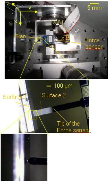
Fig. 1 displays the set up developed to measure the pull-off force between two planar surfaces. Both of these surfaces are made of silicon and the contact area is 50x50 µm2. Surfaces resulting from DRIE machining are used because they are one of the most common ways to produce microcomponents in a aim of micro-assembly. Surface 1 is made of a wafer part fixed on a system able to generate very precise rotation around (A,x) axis. Rotators used in this set-up are SR-3610-S type from Smaract company2. They are based on piezoelectric
components and enable motions with a resolution of 3 µ◦. Surface 2 is the tip part of the force sensor, itself mounted on a 4 DOF (Degrees Of Freedom) nanopositioning system (1 rotation + 3 translations). A rotator (same as previously introduced) permits to orientate both surfaces around an axis defined by (B,z). A P-611.3 nanocube device from Physik Instrumente3 enables 3D translational motions with a stroke
of 100 µm and a resolution of 1 nm. It is used to modify the relative positioning between the tip of the force sensor and the plan.
B. Measurement procedure
This 5 motorized DOF nanopositioning system (3 transla-tions x-y-z + 2 rotatransla-tions Rx-Rz) is used to quantify the pull-off force that appear between surface 1 and 2. To obtain reliable
1www.femtotools.com 2www.smaract.de
3www.physikinstrumente.com
Fig. 1. SET-UP FOR MEASURING PULL-OFF FORCE: A FORCE
SENSOR IS MOUNTED ON A XYZ NANOMETRIC STAGE. TWO RO-TATIONS ARE POSSIBLE (A,X) AND (B,Z).
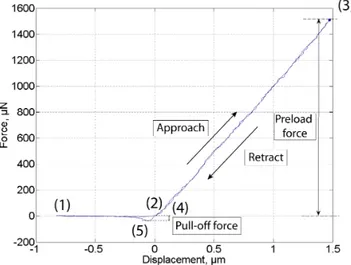
and repeatable measurements, a precise procedure has to be used. First, both surfaces should be cleaned. In the present case a pyranha (mixture based on sulphuric acid and hydrogen peroxide) is used to clean the surfaces. Then, both surfaces are relatively positioned (manual micropositioning stages). Finally approach/retract motions are generated using the y axis. A relative angle between both surfaces can be applied using one of both rotary stages. Fig. 2 shows a typical curve of approach retract that are obtained. This experimental result displays several steps:
• - step (1): there is no contact between both surfaces,
• - step (1) to (2): an approach motion is generated, • - step (2): a contact appears between both surfaces, • - step (2) to (3): the motion along y generates a
• - step (3): stop of the motion along y, the final value of the preload force is obtained,
• - step (3) to (4): a moving back motion along y is generated causing a retract relative motion,
• - step (4): the force between both surfaces is canceled but the contact between both surfaces is still present,
• - step (4) to (5): the moving back motion continues,
a negative force happens between both surfaces due to “sticking effects”,
• - step (5): the contact between both surfaces is suddenly broken, enabling the quantification of the pull-off force,
• - step (5) to (1): a retract motion continues without any contact between both surfaces.
Fig. 2. APPROACH/RETRACT CURVE SHOWING A PULL-OFF FORCE OF 20 µN BETWEEN 2 SURFACES OF 50X50 µM2.
C. Experimental results
Numerous measurements showed that temperature, hygrom-etry, preload force and approach/retract speed have few in-fluence on the amplitude of the pull-off force. During ex-periments, these parameters variation range was respectively between 24 to 28◦C, 35 and 45%, 400 to 1200 nm/s and 50 to 1200 µN and caused a variation of the measured pull-off force smaller than 10 %. Several experiments have also been done at different location of the substrate but once again no large variation have been observed.
The main influent parameter observed is the relative angle between both surfaces. In our case, several successive mea-surements have been done with successive small variations of one angle between both surfaces. The angle variation is studied in a range of −4◦to 4◦and measurements showing the influence of the relative angular positioning of both surfaces are obtained. Fig. 3 displays this influence. These measure-ments show that the pull-off force is strongly dependent to the relative orientation between both surfaces. More details about experimental conditions, measurements and comparison with conventional models can be obtained in [16]. Pull-off force can
reach forces up to 200 µN (value decreasing rapidly when the relative orientation of both plan varies) which is not negligible during manipulation of microcomponents. Indeed, the weight force of a 200x800x1000 µm3silicon component is 4 µN and the gripping force to apply for it’s holding by a microgripper has to be in the range of 20 µN . Thus, pull-off force can strongly affect micromanipulation and micro-assembly tasks. This study also suggests that force sensors combined with visual servoing constitutes a promising solution for automated micro-assembly.
Fig. 3. INFLUENCE OF THE RELATIVE ORIENTATION BETWEEN
BOTH PLANAR SURFACE ON PULL-OFF FORCE.
III. INFLUENCE OF PULL-OFF FORCE ON GUIDING TASKS
In this section, consequences of pull-off force during micro-assembly tasks are studied. The previous section showed that pull-off force between two planar surfaces of 50x50 µm3 can be up to 200 µN . Such value is in the same order than micromanipulation forces. Therefore pull-off force is non-negligible in micromanipulation and micro-assembly contexts. As a result, they must be taken into account during micro-assembly processes to guarantee the control of microcompo-nents positioning.
A. Guiding tasks
Several kinds of micro-assembly tasks generate planar con-tacts and are therefore subject to pull-off force, among them insertion and guiding tasks. In this paper a special focus will be done on guiding tasks because they generate pull-off force in only one direction which facilitate our analysis and study [17]. Moreover guiding tasks are common and require a very good control of the position of the component to obtain good quality assembled MOEMS. Micro-Optical Benches (microspectrom-eters, optical monomode fiber alignment, sensors...) notably reconfigurable free space ones can be assembled. Previous works deal with such problematics [18][19].
This papers focuses on guiding tasks based on active mi-crogripping systems. Fig. 4 shows an example of a guiding task that is based on a micromirror fixed on a substrate
(left part of the figure) thanks to two small springs and a rail. The left hand side of the figure shows the same mirror and a microgripper that enables its manipulation and guiding into the rail. To succeed such pick and place tasks, the two tips of the microgipper grip the mirror at point A and B respectively and the gripping motion warps the flexible springs of the mirror enabling motions along X (axis of the guiding). Successive steps of gripping, guiding, releasing thus enable to guarantee the good positioning and/or the reconfigurability of the assembled system.
Fig. 4. MICROMIRROR FIXED ON A SUBSTRATE (LEFT FIGURE)
AND MICROGRIPPER (RIGHT FIGURE) USED FOR IT’S MANIPULA-TION AND GUIDING INTO THE RAIL.
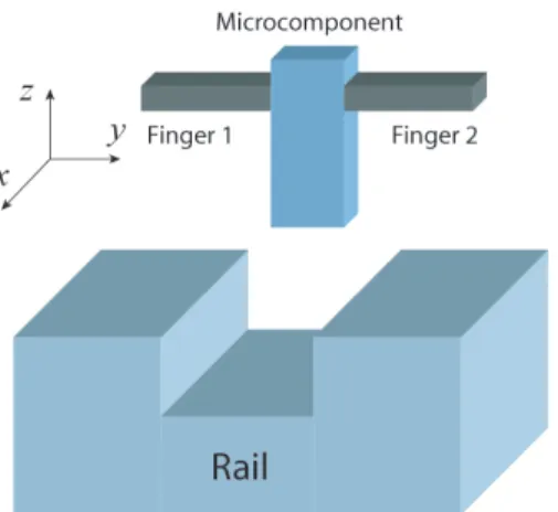
Generally, a guiding tasks consists in a microcomponent hold by the microgripper and a relative motion applied be-tween the substrate (that includes a rail) and the manipulated component. It can be schematized by Fig. 5. The final objective consists in positioning the microcomponent along x before releasing it in the rail (generally a fixing system enables to hold this position). During this guiding task, contacts between the rail and the component often happen. They are source of a contact force along x and y and sometimes along z.
Fig. 5. SCHEME OF A GUIDING TASK: A COMPONENT IS HOLD BY A MICROGRIPPER AND A RELATIVE MOTION BETWEEN SUBSTRATE AND COMPONENT IS GENERATED.
B. Guiding strategy
At the macroscale, guiding strategies generally consist in establishing a contact between the component and the rail and rubbing along the side of the rail by controlling the contact
force. This is generally done through open loop control using compliant elements or through closed loop control based on force sensors. This general principle is possible due to a good stability of the component when held by the gripper. Moreover components are not generally fragile in regard with the robot compliance. Such strategies are extremely difficult to achieve at the microscale. Indeed, scale effects decrease a lot the stability of the held component (surface forces becomes predominant in regard with volumic forces) and components as well as micromanipulators are very fragile.
For example when a contact between the microcomponent and the rail appears, a Fx force also appears. This force
can generate the bending of the component if the following equation is not validated [17]:
Fx≤
4 · Fy· µ · R
3 · l
where Fy is the gripping force to hold the component, µ
is the friction coefficient, R the equivalent radius of the contact surface between the component and the gripper and l the distance between the applied force Fxand center of the
rotation of the component. At the microscale, we can consider Fy= 1000µN , µ = 0.3, l = 500µm and R = 25µm giving a
maximum Fxforce before bending of 20 µN . This force being
so small that it is extremely difficult to guide a component into a rail without causing its rotation between the fingers of the microgripper. Moreover, technical reasons (microfabrication capabilities as well as limitations of the free space) do not allow to generate guiding motions along an axis perpendicular to the microgripper. It is therefore not possible to change the configuration of the guiding, so specific strategies must be used at the microscale. Among them, it is necessary to add sensors on both fingers of the microgripper where one is used for guiding tasks, a second one is useful for gripping tasks.
To make possible the guiding of a component into the rail without causing its rotation and so its possible loss, it is also necessary to:
• 1 - limit the guiding speed along x,
• 2 - stop the motion when a contact is detected,
• 3 - move along y in order to remove the contact,
• 4 - move again along x when the contact is removed. This strategy is specific at the microscale because sliding with contact (usually practiced a the macroscale) is not adapt-able at the microscale due to unsuitadapt-able compliance. Fig 6 illustrates these two approaches. One of the main difficulties of the microscale strategies lies in step 3 due to the presence of pull-off force. Indeed, during this step, a planar contact between the component and the gripper is established and a motion along the normal axis of the planar contact has to be done. Section 2 shows that the pull-off force can reach 200 µN which is in the range of contact and applied forces. When the contact between both surfaces is canceled, a vibration of the component can happen and generate an overshoot of the position in the rail (along y). If the axial play (δ = d1− d2
see Fig. 6) of the rail is not sufficient, then, the amplitude of this overshoot can generate a contact of the component with
Fig. 6. GUIDING STRATEGIES DEPENDING ON THE CONSIDERED SCALE.
the opposite surface. Again due to pull-off force, this means that the component can adhere to the other side of the rail. So, the axial play between the rail and the component has to be well designed to fit with the stability of the manipulator in order to guarantee the guiding. This play is mainly linked to the maximum amplitude of the pull-off force and the stiffness of the micromanipulator.
C. Experimental validation
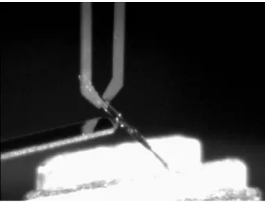
This section introduces an experimental set-up used to show the influence of pull-off force during guiding tasks. A FT-G100 microgripper from FemtoTools is used. It enables the manip-ulation of components of 10 to 100 µm in size components. It has 2 fingers, one working as an actuator, the other as a sensor, both being based on electrostatic principles. Forces in the range of 50 µN are sensed. A silicon microcomponent is held by this gripper and a FT-S540 force sensing probe is used to apply a lateral force on it (see Fig. 7).
As explained in section 3.2, a guiding strategy requires to stop the guiding motion when a contact between the ma-nipulated component and the environment appears. Thus, the proposed set-up enables to observe very precisely phenomenon happening during guiding steps especially ones consisting in
Fig. 7. SET-UP USED TO SHOW THE INFLUENCE OF PLANAR PULL-OFF FORCE DURING MICRO-ASSEMBLY STEPS: A FORCE SENSING PROBE APPLYING A LATERAL FORCE ON A SILICON COMPONENT HOLD BY A MICROGRIPPER.
removing the contact. Fig. 8 shows the measured gripping force (measured with the force sensor of the microgripper) and the measured contact force applied on the component (with the force sensing probe). During these experiments, a relative motion along the force sensing probe is generated using the nanocube nanopositioning system. In these experiments a grip-ping force of 77 µN is applied to hold the microcomponent. This force is disturbed when a contact happens between the probe and the component. When the probe is retracted, a pull-off force of 2 µN clearly appears and generates the vibration of the component. In this experiment, a displacement of 6.6 µm of the probe is necessary to cancel the pull-of force.
Fig. 8. EXPERIMENTAL RESULTS SHOWING THE PRESENCE
OF PULL-OFF FORCE: EXTERNAL APPLIED FORCE APPLIED ON THE COMPONENT AND GRIPPING FORCE EVOLUTIONS ARE DIS-PLAYED.
IV. CONCLUSION
This paper introduces a measurement set-up used to char-acterize pull-off force for planar contacts at the microscale. It shows that pull-off force can reach 200 µN for 50x50 µm2 planar contacts making it greatly influent for
applica-tions like micromanipulation or micro-assembly tasks. The study establishes that the relative orientation of both planar surfaces is the most influent parameters and it’s influence has been characterized. The consequence of pull-off force during guiding tasks (at the microscale) has also been studied and experimentally validated. It shows that approaches currently used at the macroscale (holding of a contact and control of contact force through compliance) are not yet valid. Indeed the presence of pull-off force would generate the loss of the manipulated object in most cases. To guarantee the success of a guiding tasks, microforce sensors have to be used and a strategy based on contact removing has priority in front of moving forward motions. Pull-off force also induces specific design rules notably for plays required to succeed in micro-assembly operations. Future works will deal with the automa-tion of guiding tasks based on hybrid force/posiautoma-tion control applied to MOEMS assembly.
V. ACKNOWLEDGMENT
These works have been partially funded by the French region Franche-Comte under the MIAAMI project. We would like to acknowledge Patrick Rougeot, Michael Gauthier and David Guibert for discussions and help.
REFERENCES
[1] Tolfree, D., and Jackson, M. J., 2006. Commercializing Micro-Nanotechnology Products. CRC Press.
[2] Das, A., Zhang, P., Lee, W. H., Stephanou, H., and Popa, D., 2007. “µ3 : Multiscale, deterministic micro-nano assembly system for construction of on-wafer microrobots”. IEEE International Conference on Robotics and Automation, pp. 461–466.
[3] Dechev, N., Ren, L., Liu, W., Cleghorn, W. L., and Mills, J. K., 2006. “Development of a 6 degree of freedom roboticmicromanipulator for use in 3d mems microassembly”. In IEEE International Conference on Robotics and Automation.
[4] Brussel, H. V., Peirs, J., Reynaerts, D., Delchambre, A., Reinhart, G., Roth, N., Weck, M., and Zussman, E., 2000. “Assembly of microsystems”. Annals of the CIRP, 49(2), pp. 451–472.
[5] Tamadazte B., Arnould T., D. S. L. F. P. N. M. E., 2009. “Real-time vision-based microassembly of 3d mems”. In IEEE/ASME International Conference on Advanced Intelligent Mechatronics.
[6] Lambert, P., and R´egnier, S., 2006. “Surface and contact forces models within the framework of microassembly”. Journal of Micromechatronics, 3, p. 123157.
[7] Drummond, C., and Richetti, P., 2007. Fundamentals of Friction and Wear. Springer Berlin Heidelberg, ch. Surface Forces Apparatus in Nanotribology, pp. 15–33.
[8] Leckband, D., 2008. Handbook of Molecular Force Spectroscopy. Springer US, ch. Surface Force Apparatus Measurements of Molecular Forces in Biological Adhesion, pp. 1–22.
[9] Fearing, R. S., 1995. “Survey of sticking effects for micro parts handling”. In International workshop on Intelligent Robots and Systems. [10] Cl´evy, C., Hubert, A., and Chaillet, N., 2008. “Flexible micro-assembly system equiped with an automated tool changer”. Journal of micro-nano mechatronics,4(1), pp. 59–72.
[11] Gauthier, M., R´egnier, S., Rougeot, P., and Chaillet, N., 2006. “Forces analysis for micromanipulations in dry and liquid media”. Journal of Micromechatronics,3, pp. 389 – 413.
[12] Savia, M., Koivo, H., and Zhou, Q., 2006. “Evaluation of adhesion forces between arbitrary objects for micromanipulation”. Journal of Micromechatronics,3, pp. 221 – 238.
[13] Ando, Y., 2008. “Effect of contact geometry on the pull-off force evalu-ated under high-vacuum and humid atmospheric conditions”. Langmuir, 24, pp. 1418–1424.
[14] Alvo, S., Lambert, P., Gauthier, M., and R´egnier, S., 2009. “Adhesion model for micromanipulation based on van der Waals forces”. Journal of Adhesion Science Technology,To appear.
[15] Butt, H., Cappella, B., and Kappl, M., 2005. “Force measurements with the atomic force microscope: Technique, interpretation and appli-cations”. Surface Science Reports, 59, p. 1152.
[16] Rabenorosoa, K., Cl´evy, C., Lutz, P., Gauthier, M., and Rougeot, P., 2009. “Measurement setup of pull-off force for planar contact at the microscale”. Micro Nano Letters, 4, pp. 148 –154.
[17] Rabenorosoa, K., Clevy, C., and Lutz, P., 2010. “Active force control for robotic micro-assembly: Application to guiding tasks”. In IEEE International Conference on Robotics and Automation.
[18] Rabenorosoa, K., Das, A. N., Murthy, R., Cl´evy, C., Popa, D., and Lutz, P., 2009. “Precise motion control of a piezoelectric microgripper for microspectrometer assembly”. In ASME’09 International Design Engineering Technical Conferences (IDETC’09) & Computers and Information in Engineering Conference (CIE’09)., San Diego, United States.
[19] Rabenorosoa, K., Cl´evy, C., Lutz, P., Bargiel, S., and Gorecki, C., 2009. “A micro-assembly station used for 3d reconfigurable hybrid moems assembly”. In IEEE International Symposium on Assembly and Manufacturing.