Département de génie civil
ASSESSMENT OF THE LONG-TERM
PERFORMANCE OF GFRP BARS SUBJECTED TO
DIFFERENT ENVIRONMENTAL EXPOSURES
UNDER HIGH SUSTAINED LOADS
ÉVALUATION DE LA PERFORMANCE À LONG TERME
DE BARRES D’ARMATURE EN PRFV SOUMISES À
DIFFÉRENTES CONDITIONS ENVIRONNEMENTALES
SOUS CHARGES DE TRACTION SOUTENUES ÉLEVÉES
Thèse de doctorat
Spécialité : génie civil
Yasin ESMAEILI HESAR
Sherbrooke (Québec) Canada
janvier 2021
MEMBRES DU JURY
Professeur Brahim Benmokrane Directeur de thèse
Professeur John Newhook Co-directeur
Professeur Mathieu Robert Rapporteur et examinateur
Professeur P. Vijay Examinateur
Dr. Patrice Cousin Examinateur
ABSTRACT
The long-term performance of glass fiber reinforced polymer (GFRP) bars subjected to high sustained loads and aggressive environmental conditions is not entirely clear and very conservative limits are imposed by available FRP design guidelines and codes. A two-phase (Phase I and Phase II) experimental program was designed to address this issue.
Phase I included an experimental investigation and statistical approach to assess the long-term performance and to delong-termine a safe creep-rupture strength value for glass fiber-reinforced polymer (GFRP) bars subjected to different types of environmental exposure. The study sample consisted of 160 bars of various sizes (10 mm, 12 mm, and two types of 15 mm) subjected to different levels of environmental conditioning (unconditioned and exposed to an alkaline solution at 23°C and 60°C) and a range of sustained load levels (40% to 90% of the ultimate tensile strength). The test results were analyzed with Weibull statistical analysis to determine the mean and characteristic creep-rupture strengths, and consequently, a safe design value was calculated. Limitations and variations of the strength degradation model for the life-span prediction was assessed. The impact of sustained load on strength reduction was more pronounced than the combined effect of the alkaline solution and high temperature. The GFRP bars with smaller diameters were more susceptible to creep rupture than the larger ones, while the conditioning had more effect on the bars with larger diameters than the smaller ones.
In Phase II, a set of experiments was conducted to assess the flexural behavior of concrete beams reinforced with GFRP bars subjected to a high sustained flexural load after 10 years of natural aging. The experimental program consisted of eight rectangular concrete beams measuring 250 × 250 × 2000 mm. All beams were reinforced with sand coated GFRP bars. Four beams were subjected to a high sustained load of up to 40% of the ultimate tensile capacity of their GFRP bars with simultaneous exposure to aggressive natural weathering (temperatures ranging from -25℃ to 35℃) for 10 years. The remaining four were stored in the laboratory and treated as control specimens without any loading. The conditioned beams were tested up to failure in a four-point bending setup. The results were compared in terms of load–displacement behavior, ultimate strength, displacement capacity, failure modes, and cracking pattern. In addition, the microstructure of the GFRP bars was studied to evaluate the physical changes of the bars, and their bond condition with surrounding concrete at different stress levels. The findings indicate a strength deterioration of only 16% for this early generation of GFRP bars under harsh natural conditioning and high sustained loads for 10 years. On the other hand, the bond between the concrete and GFRP bars as well as the glass transition temperature, infrared spectra and interlaminar shear strength of the GFRP bars remained unaffected. Finally, analytical approaches were implemented to predict the load–displacement behavior and crack widths of the tested beams.
Keywords: Creep rupture strength; GFRP bar; Durability; Environmental conditioning;
Sustained load; Environmental reduction factor; Design codes; Natural weathering; High sustained stress; Failure mode; Bond behavior; Deflection; Non-destructive testing.
RÉSUMÉ
La performance à long terme des barres en polymère renforcé de fibres de verre (PRFV) soumises à des charges soutenues élevées et à des conditions environnementales agressives n'est pas tout à fait clairement définie et des limites sévères sont imposées par les guides de conception disponibles. Un programme expérimental en deux phases est conçu pour étudier cette question. Dans la phase I, la résistance à la rupture par fluage des barres de PRFV exposées à différentes conditions environnementales est évaluée pour la nouvelle génération de barres. La phase II examine le comportement en flexion de poutres en béton ayant subi un vieillissement naturel et qui ont été renforcées avec la génération précédente de barres de PRFV. La première phase est réalisée en laboratoire et la seconde phase est une étude sur le terrain.
La première série d'expériences est réalisée sur 170 barres et englobe une variété de diamètres de barres (10 mm, 12 mm et deux types de 15 mm), de conditionnement environnemental (non conditionné et exposé à une solution alcaline à 23 °C et 60 °C) et de charges soutenues imposées (40 à 90 % de la résistance ultime à la traction des barres). Les résultats des essais ont été analysés à l’aide d’une analyse statistique de Weibull afin de déterminer les résistances moyennes et les résistances caractéristiques de ruptures par fluage et par conséquent, une valeur sûre pour le dimensionnement a été calculée. Les limites et les variations du modèle de dégradation de la résistance pour la prédiction de la durée de vie ont été discutées. En outre, la microstructure des barres de PRFV non rompues a été
étudiée pour évaluer les changements physiques des barres. Les résultats de l'étude montrent que le taux de dégradation est prolongé pour des niveaux de charges soutenues plus faibles. L'impact d'une charge soutenue sur la réduction de la résistance est plus prononcé que l'effet couplé d'une solution alcaline et d'une température élevée. Les facteurs de réduction de la rupture par fluage (Cc) prescrits par les codes de conception actuels sont conservateurs pour
les barres de PRFV dans cette étude. Un facteur de réduction environnemental égal à 1,0 peut être utilisé avec les limites de rupture par fluage spécifiées par les codes actuels pour les barres de PRFV noyées dans du béton, non en contact avec le sol et non exposées aux intempéries.
La deuxième série d'expériences a examiné le comportement en flexion de poutres en béton renforcées par des barres de PRFV et soumises à une charge soutenue élevée de flexion après 10 ans de vieillissement naturel. Le programme expérimental comprenait huit poutres rectangulaires en béton mesurant 250 x 250 x 2000 mm. Toutes les poutres ont été renforcées avec des barres de PRFV revêtues de sable. Quatre poutres ont été soumises à une charge élevée soutenue allant jusqu'à 40 % de la résistance ultime en traction des barres de PRFV, avec une exposition simultanée à un vieillissement naturel agressif (températures allant de -25℃ à 35℃) pendant 10 ans. Les quatre autres poutres ont été entreposées au laboratoire comme spécimens témoins sans aucune charge. Les poutres conditionnées ont été testées en flexion quatre points jusqu'à la rupture. Les résultats ont été comparés en termes de comportement charge-déplacement, de résistance ultime, de capacité de déplacement, de modes de rupture et de patron de fissuration. De plus, la microstructure des barres de PRFV a été étudiée pour évaluer les changements physiques des barres et leur adhérence avec le
béton environnant à différents niveaux de contrainte. Les résultats indiquent une détérioration de la résistance de seulement 16 % pour cette première génération de barres de PRFV, dans des conditions naturelles difficiles et sous des charges élevées soutenues
pendant 10 ans.En revanche, l'adhérence entre le béton et les barres de PRFV, ainsi que la
température de transition vitreuse, les spectres infrarouges et la résistance au cisaillement interlaminaire des barres de PRFV n'ont pas été affectés. Enfin, des approches analytiques ont été mises en œuvre pour prédire le comportement charge-déplacement et l’ouverture des fissures des poutres testées.
Mots-clés : Résistance à la rupture par fluage, barre de PRFV, durabilité, conditionnement
environnemental, charge soutenue, facteur de réduction environnemental, codes de conception, intempéries naturelles, contrainte soutenue élevée, mode de rupture, adhérence, flèche, essais non destructifs.
ACKNOWLEDGMENTS
I would like to sincerely thank my supervisor, Professor Brahim Benmokrane and my co-supervisor Professor John Newhook for initially believing in me and giving me the opportunity to perform this Ph.D. Their advice and guidance throughout the study period have been invaluable. Working with them has been inspirational for me and certainly, I have learnt a lot from them.
I am also very grateful to Dr. Khaled Ahmed MMohamed and Dr. Abolfazl Eslami for their constant support, continuous encouragement, consulting, and guidance throughout the Ph.D.
I am also I am also very grateful to the members of jury: Professor Mathieu Robert, Professor P. Vijay and Dr. Patrice Cousin for their time in reviewing my thesis.
My sincere gratitude goes to the Natural Science and Engineering Research Council of Canada (NSERC), the Network of Centre of Excellence (NCE) of Canada, the NSERC Research Chair in Innovative FRP Reinforcement for Sustainable Concrete Infrastructures, the Tier-1 Canada Research Chair in Composite Materials for Civil structures, and the University of Sherbrooke Research Centre on Composite Materials (CRUSMaC) from where the project received its financial support.
I would also like to thank all my colleagues and friends at the University of Sherbrooke for their support friendliness streamlined during the period of Ph.D. I wish to express my gratitude to the technical staff of the Center for Material Characterization (CCM) and the
materials and structural laboratory at the University of Sherbrooke and Dalhousie University.
Last but certainly not least, I would like to say a special thank you to all my family members, who were patient and helped me to complete this research work.
TABLE OF CONTENTS
ABSTRACT ... II RÉSUMÉ ... IV ACKNOWLEDGMENT ... VII TABLE OF CONTENTS ... IX LIST OF TABLES ... XVLIST OF FIGURES ... XVII
INTRODUCTION ... 1
STATEMENT OF THE PROBLEM ... 1
MOTIVATION OF THE RESEARCH ... 3
OBJECTIVES AND SCOPE ... 4
OUTLINE OF THE DISSERTATION ... 6
LITERATURE REVIEW ... 8
GENERAL ... 8
CREEP ... 10
AGGRESSIVE ENVIRONMENTAL CONDITIONS ... 12
Resin ... 14
Fiber ... 14
Fiber/Matrix Interface ... 16
The Synergic Effect of Sustained Load and Aggressive Environment... 17
Accelerated Aging Tests of GFRP Bars ... 19
Performance of GFRP Bars Under Natural Aging ... 20
Micro-Structural and Physicochemical Analyses ... 22
Design Code Provisions... 23
ASSESSMENT OF CREEP RUPTURE AND LONG-TERM PERFORMANCE OF GFRP BARS SUBJECTED TO DIFFERENT ENVIRONMENTAL EXPOSURE CONDITIONS UNDER HIGH SUSTAINED LOADS 26 ABSTRACT ... 27 INTRODUCTION ... 28 EXPERIMENTAL INVESTIGATION ... 31 Material Properties ... 31 Testing scheme ... 33
Loading protocol and test setup ... 34
TEST RESULTS... 38
DATA ANALYSIS METHODOLOGY ... 41
Statistical Distributions ... 42
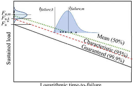
Creep rupture curves ... 44
Safety factor ... 46
ANALYSES AND DISCUSSIONS ... 47
Conditioning Group A ... 48
Conditioning Group B ... 51
Conditioning Group C ... 55
CONCLUSION ... 58
PERFORMANCE OF GFRP-REINFORCED CONCRETE BEAMS SUBJECTED TO HIGH SUSTAINED LOAD AND NATURAL AGING FOR 10 YEARS 62 ABSTRACT ... 63
INTRODUCTION ... 64
Accelerated Aging Tests of GFRP Bars ... 65
Performance of GFRP Bars Under Natural Aging ... 67
Review of Code Provisions ... 70
EXPERIMENTAL PROGRAM ... 71
Description of Test Specimens ... 73
Material Properties ... 75
Application of Sustained Load ... 76
Test Setup and Instrumentation ... 80
EXPERIMENTAL RESULTS AND DISCUSSION ... 81
Moment-Deflection Response ... 83
Bond Interface ... 85
Differential Scanning Calorimetry ... 90
FTIR Analysis ... 92
Interlaminar Shear Strength ... 93
ANALYTICAL EVALUATION ... 96
Deflection ... 96
Crack Width ... 98
CONCLUSIONS ... 100
GENERAL CONCLUSIONS AND RECOMMENDATIONS ... 104
CONCLUSIONS ... 105
Assessment of Creep Rupture Strength of GFRP Bars Subjected to Different Environmental Exposures under Sustained Loads... 106
Performance of GFRP-RC Beams Subjected to High Sustained Load and Natural Aging for 10 Years 108
RECOMMENDATIONS FOR FUTURE WORK ... 109 RÉSUMÉ ... 110
CONCLUSIONS ... 111
Évaluation de la résistance à la rupture par fluage des barres de PRFV soumises à différentes expositions environnementales et charges soutenues... 112
Performance des poutres en béton armé de PRFV soumises à une charge élevée et à un vieillissement naturel pendant 10 ans ... 114
RECOMMANDATIONS POUR LES TRAVAUX FUTURS... 115
LIST OF TABLES
Table 3-1. Physical and mechanical properties of the specimens. ... 32
Table 3-2. Load level and environmental conditioning of the tested GFRP for creep rupture ... 34
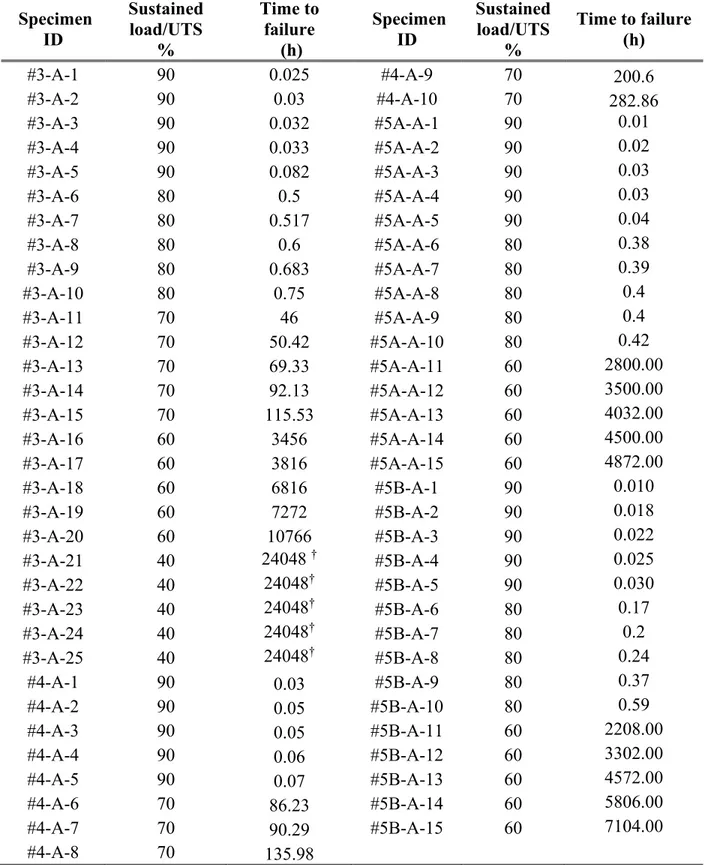
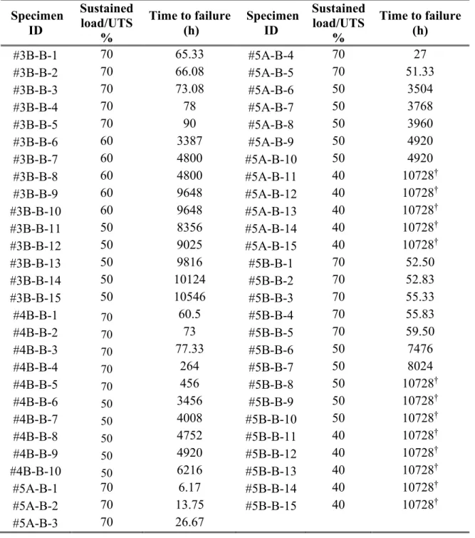
Table 3-3. Creep rupture test results for bar exposed to conditioning Group A. ... 39
Table 3-4. Creep rupture test results of bars exposed to conditioning Group B. ... 40
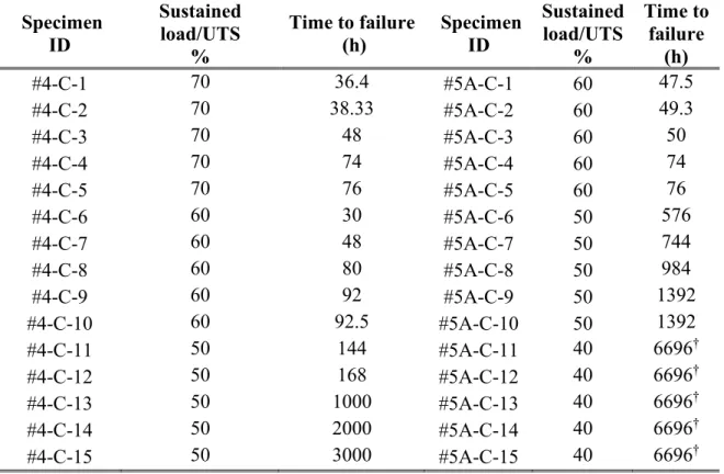
Table 3-5. Creep rupture test results of bars exposed to conditioning Group C ... 41
Table 3-6. Estimated average and guaranteed creep rupture strengths for the tested GFRP bars. ... 58
Table 4-1. Mechanical properties of the longitudinal GFRP reinforcement and the stirrups ... 76
Table 4-2. The size of initial cracks ... 78
Table 4-3. Values and variations in the flexural response of the beams reinforced with GFRP bars before and after conditioning ... 85
Table 4-5. Results of the horizontal shear test performed on the GFRP bars extracted from different stress levels ... 96
LIST OF FIGURES
Fig. 2-1 A thin layer formed around the fiber - "etching phenomenon"(Yilmaz 1992) ... 15
Fig. 2-2 Small pits appear on the surface of fiber as a result of corrosive reaction and out-migration of silicon atoms from fiber structure (Helbling et al. 2006) ... 16
Fig. 2-3 Coupled effect of sustained load and moisture absorption (Wu et al. 2014) ... 18
Fig. 2-4 Effect of applied stress and failure mechanism on time-to-failure (schematically) (Nkurunziza et al. 2005) ... 18
Fig. 3-1. GFRP bars used for creep rupture tests. ... 32
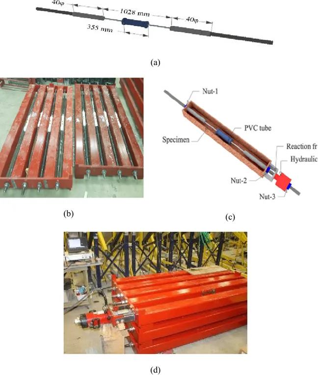
Fig. 3-2 .Loading and conditioning system used for Specimens: a) dimensions and overview of the GFRP specimens b) testing frame, c) device for sustained load application, d) readjustment of sustained load level, in an inspection session, using extensimeter and data acquisition system. ... 36
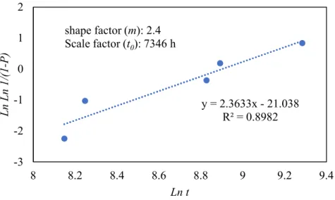
Fig. 3-3. Weibull distribution parameters for a #3 bar subjected to Group A conditioning at 60% sustained load. ... 43
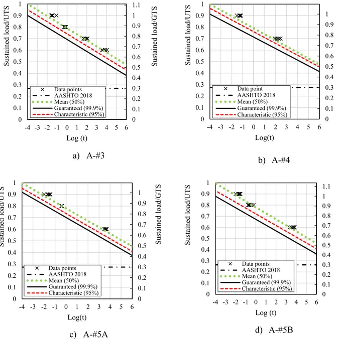
Fig. 3-5. Sustained load versus logarithmic time-to-failure, for a) bar #3, b) bar #4, c) bar #5A and d) bar #5B, subjected to conditioning type A. ... 49
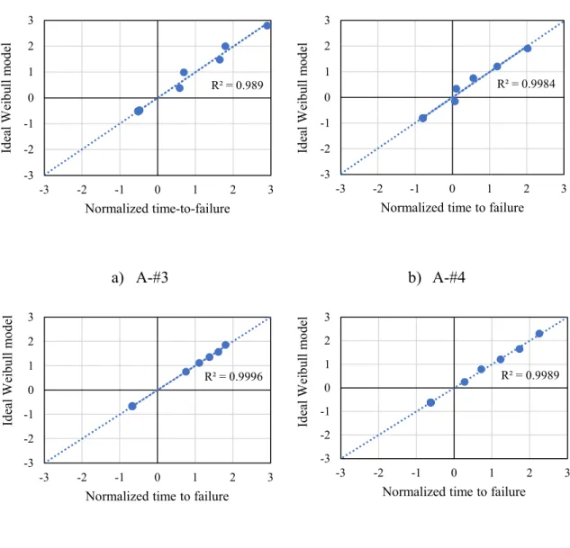
Fig. 3-6. Actual time to failure fitting to Weibull model for a) bar #3, b) bar #4, c) bar #5A, d) bar #5B, subjected to conditioning type A ... 50
Fig. 3-7. Sustained load versus logarithmic time-to-failure, for a) bar #3, b) bar #4, c) bar #5A and d) bar #5B, subjected to conditioning type B. ... 53
Fig. 3-8. Actual time to failure fitting to Weibull model for a) bar #3, b) bar #4, c) bar #5A, d) bar #5B, subjected to conditioning type B. ... 54
Fig. 3-9. Sustained load versus logarithmic time-to-failure, for a) bar #4, b) bar #5A, subjected to conditioning type C. ... 56
Fig. 3-10. Actual time to failure fitting to Weibull model for a) bar #4, b) bar #5A, subjected to conditioning type C. ... 56
Fig. 4-1. The variation in temperature extremities and snowfall at the Halifax international airport’s climatological monitoring station (2008–2018) (The official website of the Government of Canada 2019) ... 73
Fig. 4-2. Geometric and reinforcement details of the test specimens (all dimensions are in mm) ... 74
Fig. 4-4. Relationship between torque and applied load for the long-term stressing frames ... 78
Fig. 4-5. a) the beams under sustained load and natural weather conditioning (December 2008); b) the beams under sustained load and natural weather conditioning (October 2009); c) number of cracks formed along the length of a conditioned beam; d) a close-up photo of a crack ... 79
Fig. 4-6. A specimen under loading (dimensions are in mm) ... 80
Fig. 4-7. Typical failure of the unconditioned beams ... 81
Fig. 4-8. Cracking patterns of the conditioned beams (C1, C2, and C3) ... 82
Fig. 4-9. Failure mode of GFRP bars in an aged beam ... 83
Fig. 4-10. Load–deflection curves for the unconditioned and conditioned beams reinforced with GFRP bars ... 84
Fig. 4-11. The moment diagram of the beams and positions of the different stress levels (all dimensions are in mm) ... 86
Fig. 4-12. Illustration of drilled samples ... 86
Fig. 4-13. Images taken by optical microscopy of the specimens at different stress levels 88
Fig. 4-14. Images taken with SEM of the specimens at different stress levels at 80 times magnification ... 89
Fig. 4-15. A typical calorimetry curve indicating 100% cure ratio of the GFRP bar ... 92
Fig. 4-16. FTIR spectra of the unconditioned and conditioned GFRP bars at different stress levels ... 93
Fig. 4-17. Interlaminar shear test setup and mode of failure of the specimens extracted from different stress levels along the length of the beams (U4, C4) ... 95
Fig. 4-18. Comparison of the deflection values obtained from experimental tests with those predicted by ACI440.1R (ACI 2015) model for the conditioned beams ... 98
Fig. 4-19. Comparison of the crack widths of the unconditioned beams (calculated values) and the conditioned beams (experimental values) ... 99
INTRODUCTION
Statement of the problem
When a new product is introduced to the market by a manufacturer, one of the main concerns is how to ensure the customers that what they buy is something durable and the performance of the product won’t fade away. Can the life cycle of the product be predicted? Is it necessary we wait for several years to examine its service life performance or might there be other solutions? To answer these questions durability science suggests several techniques and methods of conducting experiments in order to anticipate behavior of the new product over its life cycle in a shorter period of time.
Because of the long time period required for natural conditioning of materials to occur, this kind of experiment is considered as an impractical approach to evaluate durability. For this reason, the idea of accelerated aging tests as a feasible, yet accurate method to investigate the life cycle of a material, predominates in the literature. This testing method is carried out based on vulnerable characteristic of composite polymers exposed to high temperatures (artificial aging). This can be considered as a treatment of FRP composite at elevated temperatures along with other artificially made environmental conditions (e.g. high humidity, freeze-thaw cycles, wet-dry cycles, seawater, de-icing salt effect, alkalinity, etc.) so as to accelerate the changes in the properties of that material.
Over the past years, a great number of studies (Vijay 1999; S. Debaiky 2006; Chen 2006; Robert et al. 2009; Huang 2010; Davalos et al. 2011; Zh. Dong 2016, Arczewska 2018) have justified the durability behavior of FRP bars subjected to different environmental conditions using the accelerated aging test method. However, a few studies investigated their long-term durability of these material in real-life conditions. Thus, fully exploiting this technology is still limited due to several remaining unknowns and issues related to its durability in actual conditions. To overcome this issue and broaden the knowledge of engineers on the long-term performance of GFRP material, different approaches have been adopted by engineers over the years. Besides aforementioned accelerated aging, Non-destructive Evaluation (NDE) of the existing structures is also reasonable option to acquire more information and anticipate life cycle of FRP bars. Non-Destructive tests, as a complementary data source for durability studies of FRP bars, have been extensively implemented by other researchers (Oakley, and Proctor 1981, Nkurunziza et al. 2005, Mufti et al. 2007, Robert et al. 2009, Wu et al. 2014, El-Hassan and El Maaddawy 2019). The method is comprised of a group of analysis techniques (microscopy and/or physicochemical analyses) to evaluate the properties of structural systems and components, without causing damage to them.
This research project aims at investigating the durability of GFRP bars in structural and micro structural scales. The experimental program included the two common experimental environments: 1- laboratory based (accelerated aging) conditions in which the creep strength of GFRP bars is studied under different environmental exposures; and, 2- Real-life environmental (natural aging) conditions. A field investigation in which retained flexural strength of the beams reinforced with GFRP bars is studied. The creep specimens were designed to satisfy requirements of ASTM D7337 (ASTM 2019) and the beam specimens
were designed based on the Canadian Highway Bridge Design Code CHBDC CSA S6 (CSA 2019). The outputs of this research will contribute to extend the use of GFRP-RC structural components, which is an innovative solution to overcome the corrosion problems and improve the product durability. The findings of this study are expected to support the idea of increasing in service capacity of GFRP bars, by design codes, in respect with creep strength, also reassuring for the design engineers of the durability performance of the internally used GFRP bars.
Motivation of the Research
Motivations behind this study can be summarized as:
According to the clause 7.1.2.2, CSA S806 (CSA 2012), only 25% of the ultimate tensile capacity of GFRP reinforcing bars is used for serviceability limit state purposes. Similarly, the ACI 440.1R (ACI 2015) requires that the creep rupture strength be 20% of the design strength of GFRP bars. Nevertheless, advances made in manufacturing techniques have raised the hope to utilize more capacity of the GFRP bars for serviceability limit-state predictions.
The creep rupture strength of GFRP is well known to affect by concrete alkalinity and environmental exposure; however, such an effect has not been quantified to ensure the safe service-life performance of structures and highlight the potential of relaxing the over-conservative assumptions of the current code provisions.
Only a few studies have been carried out on existing in-service structures, and those that exist are based on non-destructive tests or solely considers environmental conditioning
effect without considering the deteriorating effect of sustained load. More experimental data for naturally aged GFRP RC structural components is required, so that the design code technical committees, engaged in developing standards and code provisions, can rely on more realistic data.
It is important to understand what percentage of the total degradation of GFRP bar, after conditioning, is because of the effect of sustained load and what is the contribution of environmental conditioning. In addition, the environmental coefficients (CE) suggested by ACI440.1R (ACI 2015) is to be verified by experiments.
The advancements of new generations of GFRP bars compared with old generations in terms of quality needs to be investigated. So that the design code provisions can be updated as per the-state-of-the-art.
Objectives and Scope
The objectives of the study are as follows:
The Phase I, a total of 160 GFRP bars have been tested for creep strength with varieties of bar sizes and types, different conditioning status, and a wide range of imposed sustained stress levels. The stress levels were defined by testing another 20 GFRP bars from the same types and sizes for longitudinal tensile properties. The objective of the study was to assess the long-term performance and creep-rupture strength for GFRP bars subjected to different environmental exposures. The Phase I of study also aims to assess the appropriateness of the
term × given by the ACI 440.1R (ACI 2015) and AASHTO LRFD (AASHTO 2018), and the long-term creep rupture limit specified by the Canadian Standards. A statistical analysis has been conducted to extrapolate a safe value of creep-rupture strength for conditioned and unconditioned GFRP bars. The extensive testing program devised for this project can provide detailed answers to many aspects of the creep-rupture problem of GFRP bars.
In Phase II, with the aim of increasing the serviceability limit state, the specimens in this study were loaded to 40% of the ultimate tensile strength of their GFRP bars and while exposed to harsh natural environmental conditioning for 10 years. This level of sustained stress is almost twice the threshold allowed in CSA S806 (CSA 2012), CSA S6 (CSA 2019), and ACI 440.1R (ACI 2015). It should be noted that the design codes tend to restrict GFRP bar capacity based on guaranteed tensile strength, but the sustained load applied in this study was a proportion (40%) of the ultimate tensile strength. A sustained load equal to 40% of the ultimate tensile strength is equivalent to 47% of the guaranteed tensile strength. Thus, the actual sustained stress level is 1.9 times higher than the allowable stress level for GFRP bars in CSA S806 (CSA 2012), CSA S6 (CSA 2019), and 2.4 times higher than threshold specified in ACI 440.1R (ACI 2015).
In order to achieve the objectives of this phase, two sets of tests were carried out: (1) destructive testing in which the structural flexural behavior of the beams up to failure point was evaluated using a four point bending setup, and (2) non-destructive testing in which physiochemical changes in the GFRP bar properties due to the likelihood of degradation were examined on the microstructural scale. The specimens were eventually loaded to
failure, offering an advantage over field studies which are normally carried out with non-destructive techniques.
The data obtained from the experiments were then used for analytical purposes and are discussed in terms of flexural responses of the GFRP RC beams before and after exposure to environmental conditions. Moreover, the accuracy of the existing provisions and models in the codes were verified based on the properties of the degraded GFRP bars. The outcomes can provide a detailed understanding on the durability performance of GFRP RC beams, and crucial information on increasing the serviceability limit state thresholds specified in design guidelines.
Outline of the Dissertation
This dissertation consists of five chapters; the following is a brief description of each chapter’s content:
Chapter 1 defines the problem, presents the main objectives, the motivations of the research, and provides an outline of the thesis with a brief description of each chapter.
Chapter 2 presents a review of literature on relevant work related to durability of GFRP bars. The review includes the creep and flexural behaviour of GFRP bars and covers the available field studies and in-lab research projects.
Chapter 3 presents the first paper in this dissertation entitled “Assessment of Creep Rupture Strength and Long-Term Performance of GFRP bars Subjected to Different Environmental Exposures under High-Sustained Loads”. This chapter provides an investigation of design creep strength and environmental coefficient factor of GFRP
bars through performing creep testing on 160 bar specimens exposed to: a) normal laboratory conditions, b) immersed in alkaline solution with normal laboratory conditions at 23˚C, and c) immersed in alkaline solution with elevated temperature of 60˚C. A sustained load ranging from 40% to 90% UTS was applied on the specimens. The effect of conditioning and sustained load on creep strength investigated individually. A reliable design creep strength value was derived from test data and the results were compared with the current design codes limits.
Chapter 4 presents the second paper in this dissertation entitled “Performance of GFRP-Reinforced Concrete Beams Subjected to High Sustained Load and Natural Aging for 10 Years”. This chapter investigates the flexural behavior of eight RC beams (four unconditioned and four conditioned beams) constructed using early generation of GFRP bars. The beams were exposed to the combined effect of natural environmental conditioning and high sustained bending stress (40% of the ultimate tensile strength of the GFRP bars) for 10 years. Destructive and non-destructive testing were performed on the bar properties and the likelihood of degradation was investigated.
Chapter 5 presents the summary, conclusions based on the test results, and recommendation for future research work.
LITERATURE REVIEW
General
This chapter mainly reviews previous relevant studies into the durability of GFRP bars exposed to different environmental conditions and sustained load. The present durability study is mainly focused on the creep rupture behaviour of GFRP bars and the flexural behaviour of the beams reinforced with GFRP bars. The review attempts to address the degradation mechanisms, the effective parameters in the degradation process, most vulnerable areas of the bars against chemical attacks. The degradative effect of sustained load and conditioning is discussed individually and together. Furthermore, this chapter covers previous filed studies and laboratory-based studies also elaborates the difference between exposure to aggressive laboratory conditions and natural weathering. Design provisions of GFRP bars codes and guidelines are also presented in respect with creep rupture serviceability limit state and environmental coefficient factor in this chapter.
It is known that the long-term behavior of steel bars in corrosive environment is always accompanied by ruinous problems. This deteriorating effect of corrosion on steel would reduce the stiffness and strength of concrete structures (Wang et al. 2012). Undoubtedly, degradation of reinforcing bars entails massive repair and maintenance costs. For this reason, seeking possible alternatives for reinforcement of concrete structures appears to be a legitimate thought. Various solutions have been investigated so for, including galvanized
coating, electro-static-spray fusion bonded (powder resin) coating, polymer-impregnated concrete, epoxy coatings, alloyed steel bars, and glass FRP reinforcing bars [ACI440.1R (ACI 2015)].
Investigations on applicability of GFRP reinforcing bars in the field of civil engineering dates back to 1950s (ISIS Canada, 2007). However, they were not commercially available up until late 1970s. Corrosion-resistant feature of GFRP bars along with other advantages such as high-strength to weight ratio, electrically non-conductivity, transparency to the magnetic fields and radio frequencies, etc. have increased applicability of this material in construction industry [ACI440.1R (ACI 2015)]. Consequently, in the past decades, the studies investigating internally used FRP reinforcement have been noticeably boosted in the literature.
Today, the GFRP bars are broadly used in constructions subjected to aggressive media due to its low-cost manufacturing and can withstand better than steel bars when exposed to the combination of humidity, high temperature, and chloride. This condition is common in marine structures, bridges, and parking garages and wherever de-icing slat and chloride ions are in abundance. This environment reduces alkalinity of concrete, and leads to degradation of embedded steel bars, and this, in turn, results in concrete deterioration and overall stiffness reduction of the structure [ACI440.1R (ACI 2015)].
Past research attempts (Benmokrane et al. 2002a; Tobbi et al. 2012) to understand the applicability of GFRP bars in structures have revealed many important facts about their inherent features. Today, the short-term behavior of this structural material (features such as stiffness, bending strength, axial behavior, shear strength, bonding, and so forth) are almost
well known. Nonetheless, the long-term performance of GFRP bars still requires more research [ACI440.1R (ACI 2015)]. Particularly, their behavior under the combined effect of natural weathering and sustained stresses has received scant attention in the literature. The related durability problems of GFRP bars are commonly addressed by either laboratory accelerated aging studies (Ali et al. 2018; Park et al. 2014) or field investigations (Mufti et al. 2007; Gooranorimi and Nanni 2017; Benmokrane et al. 2018).
Despite three decades of extensive research on GFRP bars, still the subject requires supportive data and detailed studies. The everyday technological advances require the standards and the engineers to get updated with the-state-of-the-art. The variety of manufacturers, manufacturing techniques, different combination of constituent materials, sizing, shape and surface coating, fiber content, etc. are the parameters that play role in the quality of the final production. Therefore, more research is required to reach universal unity.
Creep
Creep is a time-dependent deformation that terminates in rupture when accumulated creep strains result in a deformation exceeding the design limits. Creep rupture takes place for all structural materials; however, with different intensity based on the material properties. GFRP bars experience considerable time-dependent deformation when subjected to a sustained load [ACI440.1R (ACI 2015)]. Researchers indicated that a sustained load corresponding to 40% of the Ultimate Tensile Strength (UTS) would cause a creep strain on GFRP bars of 10% from the initial tensile strain for 950 days of endurance time (Can et al.
2017). At relatively higher sustained load levels, the creep elongation is accompanied by cumulative creep failure.
The early generations of GFRP bars showed 45% UTS creep strength at an extrapolated 50-year endurance time (Renaud and Greenwood 2000; Seki et al. 1997; Yamaguchi et al. 1997). However, due to insufficient material information and lack of standard test methods, the creep-rupture stress level of internal GFRP reinforcement at serviceability is strictly limited by design codes and guides [ACI440.1R (ACI 2015); CSA S806 (CSA 2012)]. Today, standard testing methods are available to the form of material specifications issued by ASTM. The requirements of ASTM D7337 (ASTM 2019) provide detailed instructions in respect with creep testing procedures.
In a more recent study, Benmokrane et al. (2019) evaluated the creep rupture strength of a collected database of 204 creep-rupture tests conducted following the requirements of ASTM D7337 (ASTM 2019). The authors extrapolated a creep-rupture strength at 106 h (114 years) of 50.7% of the average UTS. Similar results were also shown by Weber (2005) for GFRP bars with three different bars sizes of 8, 16, and 25 mm. Rossini et al. (2019) performed a refined analysis to creep-rupture data handling of two types of GFRP bars (with 13 mm diameter) and predicted a safe value for design purposes of more than 39% UTS. However, all these studies were conducted on unconditioned GFRP bars, while the presence of sufficiently adverse environmental conditions such as high temperature and high alkalinity could adversely decrease creep rupture endurance time of GFRP bars [ACI440.1R (ACI 2015)].
Very limited studies addressed the effect of environmental conditions on the creep rupture behavior of GFRP bars. Renaud and Greenwood (2000) examined the creep rupture performance of small-sized GFRP bars (6.35 mm diameter) exposed to several environments at ambient temperature and elevated temperature of 60°C. The early generation of GFRP bars resulted in a 50-years average creep rupture strength of 45.9% UTS for the reference sample, reduced to 24% and 18.8% when conditioned in cement extract (pH = 12.6) at ambient temperature and 60°C, respectively. In a more recent study, Keller et al. (2017) investigated the creep rupture strength of GFRP bars with size #5 exposed to moist concrete (pH > 13.0) at 60°C and extrapolated an average 106-h creep rupture strength of 29.7% UTS.
Aggressive environmental conditions
Despite exhibiting good corrosion resistance, long-term exposure of GFRP bars to aggressive environments could reduce their creep strength (Dejke and Tepfers 2001; Shi et al. 2017). Davalos et al. (2012) studied the behavior of GFRP bars with E-glass and vinyl ester resin embedded in a saturated concrete at 10°C and subjected to low levels of sustained loading (corresponding to 1100-1300 με - tensile strain). The findings showed that the GFRP bars could maintain 38% of their tensile strength after 50 years. Robert and Benmokrane (2013) investigated the behaviour of GFRP bars embedded in concrete designed to simulate the alkaline environment of saturated concrete. Different exposure temperatures were implemented, moderate temperature of 23°C, 40°C, and 50°C, and warm, humid application environment of 70°C. The authors predicted a long-term tensile strength retention of GFRP bars of 77% for mean annual temperature of 10°C. Similar results were also reported by Ali et al, (2018) when aging GFRP bare bars in an alkaline solution for 1000, 3000, and 5000
hours at different elevated temperature of 22°C, 40°C, and 60°C. Benmokrane et al. (2020) predicted tensile-strength retention equal to 85% UTS after 100 years for GFRP bars with vinyl ester resin subjected to an alkaline solution at 10°C. These discrepancies make design codes take conservative measures in defining safety factors for GFRP RC structures exposed to different environmental conditions.
It should be noted that the most significant deterioration of GFRP rebars as reported by many researchers was caused by the alkaline environment (Chen el al. 2006, Al-Salloum et al. 2013, D'Antino et al. 2018, Manalo et al. 2020). The alkaline solution could damage glass fibres. The ingression of alkaline solution can also degrade the fibre/matrix interface, reducing the stress transfer between fibres and consequently reducing the tensile strength. Nevertheless, the laboratory conditioning could be too severe and exposing GFRP bars to a high alkaline solution at high temperatures would not accurately represent real-life scenarios. Studies on the durability of GFRP bars exposed to natural environment (Mufti et al. 2007, Gooranorimi and Nanni 2017, Benmokrane et al. 2018) reported no degradation of GFRP bars after up to 15 years in service.
Degradation Mechanism in GFRP Bars
The internal concrete environment has high alkalinity and moisture. Depending on the type of cement and the design mixture used for concrete, pH level within concrete varies between 10.5 and 13.5 (neglecting the effect of carbonation). This alkalinity is a result of moisture uptake and hydration process in concrete, which causes growth of hydration products
with the sustained stresses applied during in-service conditions, are the major threats of durability performance of GFRP bars.
The degradation can begin at any of three major components of GFRP bars: a) fibers; b) matrix and; c) the fiber/matrix interface. Depend on different combination of constituent materials (fiber, resin, sizing chemistry, additives and fillers) different mechanisms of degradation might occur. The items discussed below elaborate more on the possible degradation scenarios of FRP bars (Dong et al. 2017).
Resin
Vinyl ester resin matrix is prone to degradation by hydrolysis when hydroxyl ions (OH )/water, present in concrete pore solution, diffuse inside. Water molecules act as a
plasticizer, resulting a swelling stress, which in turn can cause matrix cracking and fiber/matrix de-bonding. That is why it is important to use fully cured resins in GFRP reinforcing bars, as they contain less voids, holes, cracks and imperfections compared to under-cured resins. Therefore, fully cured resins more efficiently can protect the fibers from penetration of hydroxyl ions. Vinyl-ester and epoxy resins have shown low permeability and high resistance to alkaline attack and are quite tough in resisting micro-crack development. On the contrary, polyester resins are not recommended at all for this purpose.
Fiber
The fibers damage occurs due to chemical attack on the glass fibers by the alkaline environment (Yilmaz 1992). The diffusion of alkali ions in fiber structure cause leaching of Si and Na from fiber and dissolution of these atoms. This chemical reaction occurs due to
the breaking of Si-O-Si structure by hydroxyl ions (Eq. 1). In other words, the ingress of water hydrolyzes Si-0-Si bonds and is accompanied by inward diffusion of Ca ions arising from the cement, while sodium and silicon from the fiber migrate outward into the adjacent concrete paste. This phenomenon can be also observed by scanning electron microscopy (SEM) photomicrograph in two general forms: a) the formation of a thin layer (shell) around the fibers, known as “etching” (see Fig. 2-1); b) the formation of pits or notches on the surface of fibers (see Fig. 2-2). The consequence of degradation on fibers would be reduced flexibility, and deteriorated mechanical properties (Yilmaz et al. 1991).
≡ Si − O − Si ≡ + OH → Si − OH + O − Si ≡ (1)
Fig. 2-2 Small pits appear on the surface of fiber as a result of corrosive reaction and out-migration of silicon atoms from fiber structure (Helbling et al. 2006)
Fiber/Matrix Interface
Fiber/matrix interface is the weakest link in the system can be degraded easily. Numerous studies on degradation mechanism of FRP bars, all agree that the bond between fiber and resin is the most critical and vulnerable region to corrosion. Any damage in this area reduces the tensile strength of the FRP bar (Davalos et al. 2012), because the load transfer from matrix to fibers would not function properly.
It is also worth mentioning that for the bars embedded in concrete, the interface of concrete and the FRP bar also matters and should be considered as a potential degradation region.
Based on three degradation mechanisms discussed above, it can be concluded that improving the permeability features of the resin as well as improving the hydrolytic stability of the fiber/ matrix interface, can improve the durability of FRP bar (Davalos et al. 2012).
The Synergic Effect of Sustained Load and Aggressive
Environment
Benmokrane et al. (2002) investigated corrosion of GFRP bars embedded in moist concrete under different stress levels. Based on this research three types of corrosion mechanisms had been identified: 1-diffusion dominated corrosion, 2-crack-propogation-dominated corrosion, 3-stress dominated corrosion. This study tends to divide sustained stress into three separate levels: a) low stress levels (perhaps below 20% of ultimate tensile load), b) moderate stress level (e.g. 20% to 40%) c) high stress levels (above 40%). According to this classification the corrosion condition of fiber/matrix interface of GFRP bars embedded in moist concrete under different stress levels falls under each of these categories. For the stress levels below 20% resin, the stress is not sufficient to expand the voids and the micro-cracks of the matrix, so no direct attack on the interface takes place. In other words, the hydroxyl ions are only able to penetrate to the fiber/matrix interface by diffusion. For the moderate stress levels (20-40%), the stress is able to extend and expand the micro-cracks and voids of the resin. The more stress is applied the more micro-cracks appear in the resin. This allows alkaline environment of concrete attack the fiber/matrix interface directly. The degree of crack propagation is a critical factor for the residual tensile strength. Therefore, this phase is named crack-propagation-dominated stage. At last, for the stress levels above 40%, creep characteristics of the GFRP bars brings the bars to rupture after a period of time even without contact with corrosive medium. However, the alkaline environment shortens the time needed for the bar failure. It should be noted that the findings of Benmokrane et al. (2002) attributed to earlier generations of GFRP bars and should not be taken valid for the newer generations.
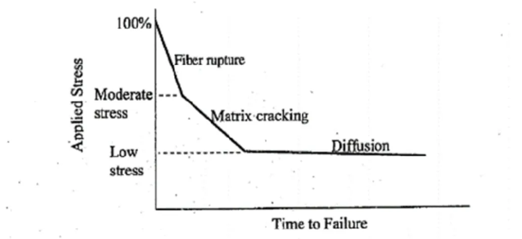
The synergetic effect of sustained load and moisture is shown in Fig. 2-3. The figure points out accelerating effect of sustained stress on corrosion. Sustained load widens the micro-cracks and the voids of resin matrix, and this allows easier penetration of the hydroxyls to the resin matrix. Consequently, accelerates erosion of the fibers/ matrix bond. Fig. 2-4 refers to the schematic correlation between applied stress/conditions and time-to-failure for GFRP bars in general.
Fig. 2-3 Coupled effect of sustained load and moisture absorption (Wu et al. 2014)
Fig. 2-4 Effect of applied stress and failure mechanism on time-to-failure (schematically) (Nkurunziza et al. 2005)
Accelerated Aging Tests of GFRP Bars
Accelerated aging tests have been widely used in durability studies due to their simplicity in establishing the life span of the GFRP bars. In this method, the alkaline solutions represent concrete pore water and the elevated temperature yields accelerated aging. He et al. (2017) conducted accelerated durability tests on GFRP reinforcement embedded in concrete beams. The bars were extracted from the beams immersed in alkaline solution at 60°C and subjected to sustained loads (20% and 40% of ultimate bending strength). After 18 months exposure to alkaline solution, the bars retained tensile strength of about 80% and 75% for the bars subjected to sustained loads of less than 20% and 40% of ultimate bending strength, respectively. Debonding of glass fibers and matrix has also been reported for GFRP bars under a sustained load equal to 40% of their ultimate bending strength. At the same time, no significant evidence of degradation was observed for sustained flexural loads of less than 20% of bar ultimate bending moment. Moreover, the authors stated that the degree of degradation could be more pronounced at the interface of the glass fibers and resin matrix. Ali et al. (2018) predicted tensile-strength retention of 85% and 75% after 200 years for GFRP bars with vinyl ester resin subjected to an alkaline solution at 10°C and 30°C, respectively. Park et al. (2014) studied the flexural behavior of 36 beams reinforced with either GFRP or steel bars subjected to the combined effect of sustained load and accelerated-aging conditions (i.e., 47°C and 80% relative humidity) for 300 days. Their experimental outcomes indicated different rates of degradation for different types of GFRP bars under artificial aggressive environments. The studies confirmed, however, that one advantage of
using GFRP bars in concrete is that they are not subjected to corrosion unlike the conventional steel reinforcement.
In contrast, some contradictory outcomes have also been reported based on the findings of accelerated tests conducted on GFRP RC structures. For instance, Davalos et al. (2012) studied the behavior of GFRP bars with E-glass and vinyl ester resin embedded in a saturated concrete at 10°C and subjected to relatively low levels of sustained loading (1100-1300 με - tensile strain). They indicated that the GFRP bars could maintain 38% of their tensile strength after 50 years. This would lead to the conclusion that GFRP bars should not be used in concrete. This paradox might be due to the variety of constituent materials in GFRP bars and the available processing techniques. These uncertainties; however, have a massive influence on the safety margin of the design process forcing engineers to adopt high safety factors for GFRP RC structures exposed to different environmental conditions.
Performance of GFRP Bars Under Natural Aging
Unlike accelerated-aging tests, natural aging is a very slow process as the properties of GFRP reinforcement are less affected by natural weathering than accelerated-aging conditions (Bakis et al. 2005; Micelli and Nanni 2004; Mufti et al. 2007; Gooranorimi and Nanni 2017; Benmokrane et al. 2018). Since the results obtained from the natural weathering conditions are more realistic and reliable than that from accelerated aging tests, conducting field studies is crucial to validate design code provisions. In an attempt, Trejo et al. (2011) studied 160 actual field-conditioned GFRP bars embedded in unsaturated cracked concrete for seven years to evaluate the effects of environmental degradation. Their results indicated lower rates
of strength deterioration compared to data available for the accelerated exposure. No sustained load was imposed on the bars, however, over seven years of exposure. In another study, Gooranorimi and Nanni (2017) performed a field study to evaluate the long-term durability conditions of GFRP bars in a 15-year old bridge (Sierra de la Cruz Bridge in Texas, USA). The durability of the GFRP bars embedded in the concrete deck and exposed to the natural environmental conditions was evaluated through a series of microstructural tests. The test results showed that the GFRP bars were in good condition even after 15 years. Nonetheless, due to limitation in obtaining data for the control specimens, the results of interlaminar shear tests were inconclusive.
Mukherjee and Arwikar (2005, 2006) conducted a comprehensive study comparing the performance of GFRP bars under accelerated aging and natural weathering in a tropical environment. The specimens for the accelerated aging test were immersed in tanks containing water at 60°C for 3, 6, and 12 months.The conditioning time of the naturally aged specimens was 18 or 30 months. In addition, 50% of the ultimate load was imposed on the beams as a sustained load. The outcomes were discussed on the structural (Mukherjee and Arwikar 2006), and microstructural (Mukherjee and Arwikar 2005) scales. Failure of the control beams was associated with the design-intended flexural-compression mode. On the other hand, the conditioned beams failed with reinforcement rupture and withstood higher loads. The tests on constituent materials showed that the concrete gained substantial strength due to conditioning in the tank at 60°C. The testing of reinforcing bars taken from the conditioned beams also revealed that the bars experienced strength drops of about 42%, 56%, and 65% with 3, 6, and 12 months of accelerated aging, respectively. Even given natural weathering, strength reductions of about 35% and 39% were observed after 18 and
30 months, respectively. The increase in concrete strength and decrease in reinforcing-bar strength shifted the failure mode from concrete crushing to reinforcement rupture. Moreover, although the resin matrix was made of vinyl ester, the extrapolated life span showed that the GFRP bars would lose 65% of their strength over a service life of 32 years. The microstructural observations also verified the degradation. The authors stated, however, that the SEM analysis points to bubbles and microcracks in the matrix that could have formed during the manufacturing process. Bubbles and microcracks facilitate the diffusion of moisture and alkaline solution.
He et al. (2013) conducted a durability investigation on E-glass reinforced vinyl-ester bars. The bars were conditioned in concrete beams for three years. During conditioning, the specimens were subjected to a sustained load equal to 11% of the ultimate tensile strength of the GFRP bars combined with different environments, including ambient indoor laboratory, natural outdoor weathering in central Pennsylvania, a high alkaline aqueous solution at 60°C, and alternating 17°C dry freeze and room-temperature water immersion. Based on the results, the tensile strength decreased by 28% for the artificially aggressive environments, while it remained unchanged for the indoor and outdoor conditioning. An extrapolation to 50 years predicted a residual strength of 50% of the ultimate strength for the former condition.
Micro-Structural and Physicochemical Analyses
Microstructural and physicochemical analyses, or so called “non-destructive tests”, are widely used in durability studies nowadays. They can provide invaluable information for
engineers and manufacturers. Microstructural tests such as Scanning Electron Microscopy (SEM), fiber volume content, water absorption, penetration, Fourier Transform Infrared Spectroscopy (FTIR), Xray test (XRF), Differential Scanning Calorimetry (DSC) and so on are useful in evaluating the long-term performance. These testing techniques are essential part of quality control/assurance process of FRP rod production lines, and are of high importance for the industrial manufacturers (Benmokrane et al. 2002).
Design Code Provisions
ACI440.1R (ACI 2015) and AASHTO LRFD (AASHTO 2018) require that material properties provided by FRP manufactures be considered as raw properties that do not include the deteriorating effect of long-term environmental exposure. The specification requires
using environmental reduction factors (CE) to reduce the material properties used in design
equations, based on the type and level of environmental exposure. The CE factor for GFRP
reinforced concrete components not exposed to earth and weather suggested by ACI440.1R (ACI 2015) is 0.8 and for the members exposed to earth and weather is 0.7. According to the concept of environmental reduction factor, the design creep strength, ∗, defined by ACI440.1R (ACI 2015) and AASHTO LRFD (AASHTO 2018) should be determined as
∗ = . . ∗
where ∗ is guaranteed ultimate tensile strength of GFRP bars and is the creep
knock-down factor (Rossini et al. 2019). The current edition of ACI440.1R (ACI 2015) specifies a creep rupture reduction factor equals to 0.2, leading to a creep-rupture tensile strength
corresponding to 0.16 or 0.14 of ∗ for elements not exposed or exposed to earth and weather, respectively. The second edition of AASHTO LRFD (AASHTO 2018), however, relaxed creep rupture reduction factor to 0.3 benefiting from the adoption of the standardized creep rupture test method, and the recent advancements in GFRP manufacturing process and material constituents. However, by using the environmental reduction factor accompanied with , the creep-rutpure tensile strength is reduced to 0.24 or 0.21 for elements not exposed or exposed to earth and weather, respectively.
Canadian Standards are pursuing a different strategy in this respect [CSA S806 (CSA 2012);
CSA S6 (CSA 2019)]. Canadian design code uses resistance factor to account for
uncertainties of material (including but not limited to environment-induced effects). In other
words, CSA S806 (CSA 2012) and CSA S6 (CSA 2019) recommend resistance factors, ,
equal to 0.75 and 0.65, respectively, for internally reinforced FRP structures where the effect of environment is taken in this coefficient. However, the resistance factors do not apply to serviceability limit states such as creep.
ASSESSMENT OF CREEP RUPTURE
AND LONG-TERM PERFORMANCE OF GFRP
BARS SUBJECTED TO DIFFERENT
ENVIRONMENTAL EXPOSURE CONDITIONS
UNDER HIGH SUSTAINED LOADS
Authors and affiliations:
Yasin Esmaeili,1 Khaled Mohamed,2 John Newhook,3 Brahim Benmokrane4*
1PhD candidate, Department of Civil Engineering, University of Sherbrooke,
Sherbrooke, QC, Canada, J1K 2R1, E-mail: [email protected]
2Postdoctoral Fellow, Department of Civil Engineering, University of Sherbrooke,
Sherbrooke, QC, Canada, J1K 2R1, E-mail: [email protected]
3Professor, Faculty of Engineering, Dalhousie University, Sexton Campus, Halifax, NS,
Canada, B3H 4R2, E-mail: [email protected]
4Professor of Civil Engineering, Tier-1 Canada Research Chair of Advanced Composite
Materials for Civil Structures and Senior NSERC Research Chair in Innovative FRP Reinforcement for Sustainable Concrete Infrastructure, Department of Civil Engineering, University of Sherbrooke, Sherbrooke, QC, Canada, J1K 2R1, Phone:
(819) 571-6923; E-mail: [email protected] (*Corresponding
Journal Title and Paper Status:
Submitted to Journal of Construction and Building Materials in January 02, 2021.
Contribution to the Thesis:
The long-term creep rupture strength of GFRP bars is well known to be affected by environmental exposure, such as concrete alkalinity and earth or weather. However, no investigation has reported such an effect. Consequently, code provisions conservatively assumed a long-term reduction of the GFRP bars creep rupture strength based on the committee consensus, and recommended future research to assess the stipulated reductions. The current study assesses and quantifies the effect of creep rupture strength of GFRP bars exposed to the alkaline solution at ambient and elevated temperature.
Abstract
This paper presents an experimental investigation and statistical approach to assess the long-term performance and to delong-termine a safe creep-rupture strength value for glass fiber-reinforced polymer (GFRP) bars subjected to different types of environmental exposure. The study sample consisted of 160 bars of various sizes (10 mm, 12 mm, and two types of 15 mm) subjected to different levels of environmental conditioning (unconditioned and exposed to an alkaline solution at 23°C and 60°C) and a range of sustained load levels (40% to 90% of the ultimate tensile strength). The test results were analyzed with Weibull statistical analysis to determine the mean and characteristic creep-rupture strengths, and consequently, a safe design value was calculated. Limitations and variations of the strength degradation model for the life-span prediction are discussed. The impact of sustained load on strength reduction was more pronounced than the combined effect of the alkaline solution and high
temperature. The GFRP bars with smaller diameters were more susceptible to creep rupture than the larger ones, while the conditioning had more effect on the bars with larger diameters than the smaller ones. The creep-rupture reduction factors prescribed in current design codes are conservative for the GFRP bars in this study.
Author keywords: Creep-rupture strength; GFRP bar; durability; environmental
conditioning; sustained load; environmental reduction factor; design codes.
Introduction
Creep is a time-dependent deformation that terminates in rupture when the accumulated creep strains result in deformation exceeding the design limits. Creep rupture occurs in all structural materials, although the intensity varies according to material properties. Glass fiber-reinforced polymer (GFRP) bars experience considerable time-dependent deformation when subjected to sustained load (ACI 440.1R [ACI 2015]). Researchers have indicated that a sustained load corresponding to 40% of the ultimate tensile strength (UTS) would cause 10% creep strain in GFRP bars from the initial tensile strain for 950 days of endurance time (Can et al. 2017). At relatively higher sustained load levels, creep elongation is accompanied by cumulative creep failure.
The early generations of GFRP bars showed 45% UTS creep strength at an extrapolated 50-year endurance time (Greenwood 2002, Seki et al. 1997, Yamaguchi et al. 1997). Due to insufficient material information and lack of standard test methods, however, the creep-rupture stress level of internal GFRP reinforcement at serviceability is strictly limited by design codes and guides (ACI 440.1R [ACI 2015], CSA S806 [CSA 2012]). Today, standard
testing methods are available in the form of material specifications issued by ASTM. The requirements of ASTM D7337 (ASTM 2019) provide detailed instructions with respect to creep testing procedures.
In a more recent study, Benmokrane et al. (2019) evaluated the creep-rupture strength of a collected database of 204 creep-rupture tests conducted according to the requirements of ASTM D7337 (ASTM 2019). The authors extrapolated a creep-rupture strength of 50.7% of the average UTS at 106 h (114 years). Weber (2005) presented similar results for GFRP bars of three different sizes (8, 16, and 25 mm). Rossini et al. (2019) performed a refined analysis of creep-rupture data for two types of GFRP bars (13 mm in diameter) and predicted a safe value for design purposes of more than 39% UTS. All these studies, however, were conducted on unconditioned GFRP bars, while the presence of sufficiently adverse environmental conditions—such as high temperature and high alkalinity—could irreversibly decrease the creep-rupture endurance time of GFRP bars (ACI 440.1R [ACI 2015]).
Very limited studies have addressed the effect of environmental conditions on the creep-rupture behavior of GFRP bars. Renaud and Greenwood (2005) examined the creep-creep-rupture performance of small GFRP bars (6.35 mm in diameter) exposed to several environments at ambient temperature and a high temperature of 60°C. This early generation of GFRP bars had a 50-year average creep-rupture strength of 45.9% UTS for the reference sample, which decreased to 24% and 18.8% when conditioned in cement extract (pH = 12.6) at ambient temperature and 60°C, respectively. In a more recent study, Keller et al. (2017) investigated the creep-rupture strength of #5 GFRP bars exposed to moist concrete (pH > 13.0) at 60°C
To account for the effect of environmental exposure on the creep-rupture strength of GFRP, ACI 440.1R (ACI 2015) and AASHTO LRFD (AASHTO 2018) require that the design-creep strength be multiplied by an environmental reduction factor (CE) to reduce the material
properties used in design equations, based on the type and level of environmental exposure.
The CE factor for GFRP-reinforced concrete components not exposed to earth and weather
suggested by ACI 440.1R (ACI 2015) and AASHTO LRFD (AASHTO 2018) is 0.8; the value for members exposed to earth and weather is 0.7. Canadian standards are pursuing a different strategy in this respect (CSA S806 [CSA 2012], CSA S6 [CSA 2019]). The Canadian design code uses a resistance factor φf to account for material uncertainties
(including but not limited to environmentally induced effects). These resistance factors do not, however, apply to serviceability limit states such as creep.
In this study, a total of 160 GFRP bars were tested for creep strength of various bar sizes and types under different conditioning types and a wide range of imposed sustained stress levels. The stress levels were defined by testing another 20 GFRP bars of the same types and sizes for longitudinal tensile properties. Few studies have been investigated the effect of creep rupture under harsh environmental exposure conditions on the long-term behavior of GFRP bars. The objective of this study was to assess the creep-rupture strength of GFRP bars subjected to severe environmental exposure throughout a comprehensive experimental investigation. A statistical analysis was conducted to extrapolate a safe value of creep-rupture strength for the conditioned and unconditioned GFRP bars. The extensive testing program devised for this project can provide detailed answers to many aspects of the creep-rupture problem of GFRP bars.
Experimental Investigation
Material Properties
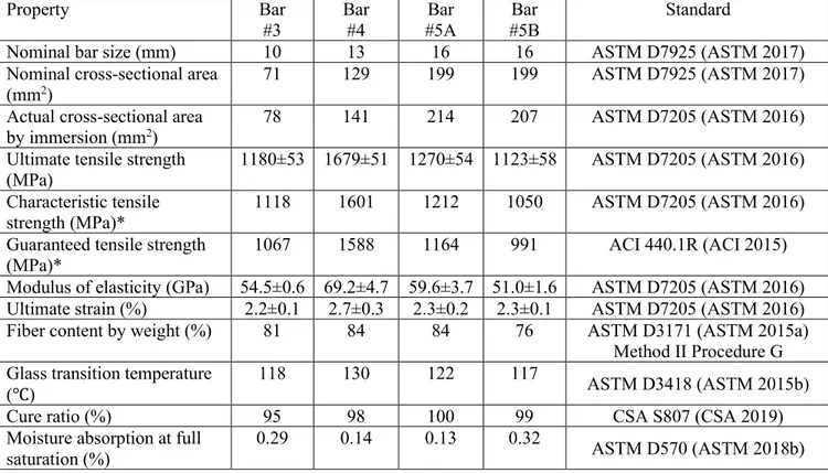
The creep rupture test specimens included three different bar sizes #3, #4 and #5 (diameters of 10 mm, 13 mm, and 16 mm, respectively). Two types of #5 GFRP bars were used in this study with different constituent materials and fiber contents. Type A was sand coated with a helically wrapped surface, while Type B was helically grooved, as shown in Fig. 3-1. On the other hand, the #3 and #4 GFRP bars had a smooth surface. The bars were manufactured according to a pultrusion process and were comprised of vinyl-ester resin and E-CR glass fibers meeting the requirements of ASTM D578 (ASTM 2018). The physical and mechanical properties of the specimens and the pertained testing method are presented in Table 3-1. The properties in Table 3-1 were measured for five different replicates cut from the bars based on the test requirement. Generally, the physical and mechanical properties of the GFRP bars were following the requirements of ASTM D7957 (ASTM 2017) and CSA S807 (CSA 2019b) specifications. Table 3-1 shows that the GFRP had various tensile strength and modulus, ranging between 1123-1670 MPa and 51-69.2 GPa, respectively.
Fig. 3-1. GFRP bars used for creep rupture tests.
Table 3-1. Physical and mechanical properties of the specimens.
Property Bar #3 Bar #4 Bar #5A Bar #5B Standard
Nominal bar size (mm) 10 13 16 16 ASTM D7925 (ASTM 2017)
Nominal cross-sectional area
(mm2)
71 129 199 199 ASTM D7925 (ASTM 2017)
Actual cross-sectional area
by immersion (mm2)
78 141 214 207 ASTM D7205 (ASTM 2016)
Ultimate tensile strength (MPa)
1180±53 1679±51 1270±54 1123±58 ASTM D7205 (ASTM 2016)
Characteristic tensile strength (MPa)*
1118 1601 1212 1050 ASTM D7205 (ASTM 2016)
Guaranteed tensile strength (MPa)*
1067 1588 1164 991 ACI 440.1R (ACI 2015)
Modulus of elasticity (GPa) 54.5±0.6 69.2±4.7 59.6±3.7 51.0±1.6 ASTM D7205 (ASTM 2016)
Ultimate strain (%) 2.2±0.1 2.7±0.3 2.3±0.2 2.3±0.1 ASTM D7205 (ASTM 2016)
Fiber content by weight (%) 81 84 84 76 ASTM D3171 (ASTM 2015a)
Method II Procedure G Glass transition temperature
(℃)
118 130 122 117
ASTM D3418 (ASTM 2015b)
Cure ratio (%) 95 98 100 99 CSA S807 (CSA 2019)
Moisture absorption at full saturation (%)
0.29 0.14 0.13 0.32
ASTM D570 (ASTM 2018b) Note: Tensile properties were calculated based on the nominal cross-sectional area.
* The characteristic and guaranteed tensile strengths were calculated using normal distribution based on probability of 0.05% and 0.001%, respectively.