Arts et Métiers ParisTech - Campus de Lille
2016-ENAM-0020
École doctorale n° 432 : Science des Métiers de l’ingénieur
présentée et soutenue publiquement par
Juliette MORIN
le jeudi 17 Novembre 2016
Coordination des moyens de réglage de la tension à l’interface réseaux de
transport et de distribution, évolution du réglage temps réel de la tension
dans les réseaux de distribution
-
Joint TSO-TSO voltage and reactive power control at HV/MV systems
interface and development of real-time Volt Var Control of distribution
networks
Doctorat ParisTech
T H È S E
pour obtenir le grade de docteur délivré par
l’École Nationale Supérieure d'Arts et Métiers
Spécialité “ Génie Electrique ”
Directeur de thèse : Xavier GUILLAUD
Co-encadrement de la thèse : Frédéric COLAS, Jean-Yves DIEULOT, Sébastien GRENARD
T
H
È
S
E
JuryM. Thierry VAN CUTSEM, Professeur, FNRS, Université de Liège Président M. Mario PAOLONE, Professeur, DESL, Ecole Polytechnique Fédérale de Lausanne Rapporteur M. Yvon BESANGER, Professeur, G2ELAB, Institut Polytechnique de Grenoble Rapporteur
M. Xavier GUILLAUD, Professeur, L2EP, Ecole Centrale de Lille Examinateur M. Frédéric COLAS, Ingénieur-Docteur, L2EP, Arts et Métiers ParisTech Examinateur M. Jean-Yves DIEULOT, Professeur, CRISTAL, Université de Lille I Examinateur M. Sébastien GRENARD, Ingénieur-Docteur, Enedis Examinateur M. Hervé LEFEBVRE, Ingénieur-Docteur, RTE Invité
Acronyms . . . viii
Acknowledgements . . . 1
General introduction . . . 3
A Voltage Control in Distribution Networks and Reactive Power Exchange at the Trans-mission and Distribution System Interface . . . 7
I Existing control and structure of electricity power system networks . . . 8
I.1 Public Electricity Distribution Networks . . . 10
I.1.1 General structure of electricity power systems . . . 10
I.1.2 Public electricity distribution networks in France . . . 11
I.1.3 Distribution and Transmission system operators . . . 13
I.2 Current practices of Voltage Control and Reactive Power Management in Distribution and Transmission Grids . . . 14
I.2.1 Control strategy at the distribution level . . . 14
I.2.2 Control strategy at the transmission/distribution system interface in France . . . 20
I.2.3 Control strategy at the transmission level in France . . . 20
Bibliography . . . 22
II Recent technical and regulatory transformation of distribution networks: a need for a new solution . . . 24
II.1 Issues raised by the recent developments in the distribution grid and the new regulatory standards . . . 26
II.1.1 Consequences of distribution networks transformation . . . 26
II.1.2 Definition of a new regulatory framework: Demand and Connec-tion Grid Codes . . . 28
II.2 New drivers and technological limitations for voltage control and reactive power exchange management in distribution networks . . . 31
II.2.1 New opportunities raised by the DGs: a reactive power modulation 31 II.2.2 Smart and active grid developments: real-time voltage control op-portunities in MV networks . . . 32
Bibliography . . . 33
III Motivation and position of the works . . . 35
III.1 Simulation architecture, tools and data . . . 39
III.1.1 Simulations overview . . . 39
III.1.3 Presentation of the systems to be studied . . . 40
III.2 Steady-state consequences of changes in distribution networks : a case study 43 III.2.1 Evolution of reactive power flows at the HV/MV interface . . . 43
III.2.2 Consequences of high reactive power flowing from MV grids . . . 46
III.3 Conclusion: relevance of real-time solution based on a greater TSO-DSO coordination . . . 51
Bibliography . . . 51
Conclusion on Part A: Relevance of real-time control strategy and a greater TSO-DSO coordination . . . 53
B Real-time Volt Var Control in Active Distribution Networks with HV-MV Reactive Power Exchange limitation . . . 54
IV Review on real-time VVC for distribution networks . . . 55
IV.1 Survey on VVC centralized control structures to manage HV/MV reactive power exchanges . . . 56
IV.1.1 Relevance of coordinated structure compared to local control strate-gies . . . 58
IV.1.2 Standard methods for coordinated voltage control . . . 60
IV.1.3 Present technical possibilities of distribution networks regarding real-time coordinated VVC . . . 65
IV.2 Introducing two usual real-time VVC schemes compliant with industrial re-quirements . . . 70
IV.2.1 A semi-coordinated rule-based voltage control: R-VVC . . . 70
IV.2.2 A coordinated optimization-based voltage control: O-VVC . . . . 73
IV.3 Conclusion . . . 75
Bibliography . . . 76
V Definition of a real-time predictive VVC with a reactive power exchange limitation 80 V.1 Predictive control strategy of voltage and reactive power exchange between HV and MV grids . . . 82
V.1.1 MPC control strategy: the MPC-VVC . . . 83
V.1.2 Networks and actuators modeling . . . 86
V.1.3 Resolution and constraints infeasibility issues . . . 87
V.1.4 MPC tuning . . . 90
V.2 Embedding the OLTC nonlinearities into the predictive VVC . . . 91
V.2.1 OLTC voltage reference generation from optimal tap changes . . . 91
V.2.2 Irrelevance of the continuous OLTC approximation . . . 92
V.2.3 Correct tap change mechanism using a discrete resolution . . . 94
V.2.4 Conclusion . . . 95
V.3 Simulation results on the three-feeder 20 kV network under external and parametric uncertainties . . . 96
V.3.1 Method to assess the performance of the MPC-VVC: robustness studies . . . 96
V.3.2 Simulation overview to illustrate the performance of the predictive VVC strategy . . . 99
V.3.3 Application of the proposed robustness study method to the
three-feeders 20kV grid . . . 102
V.3.4 Conclusion and recommendations . . . 109
V.4 Adequacy of the predictive VVC for a real 20 kV grid . . . 111
V.4.1 Case study: a severe perturbation on the HV grid . . . 111
V.4.2 Conclusion: a method suitable for large scale distribution grids . . 111
Bibliography . . . 112
VI Comparison of the predictive VVC performances compared to other standard methods115 VI.1 A qualitative comparison of VVC schemes . . . 117
VI.2 A quantitative comparison of VVC schemes on a case study . . . 119
VI.2.1 Case study and simulations without real-time VVC . . . 119
VI.2.2 Illustration of results with real-time VVC schemes . . . 121
VI.2.3 Comparison of simulations results from constraints enforcement and costs points of view . . . 125
VI.3 Conclusion . . . 127
Conclusion on Part B: A predictive real-time VVC to correct MV voltages and control HV/MV reactive power flows . . . 128
C Coordinated reactive power management in a medium scale system . . . 130
VII A DSO-TSO coordinated reactive power management scheme in a medium scale system to support TSO operations . . . 131
VII.1 Introduction . . . 132
VII.2 How distribution systems may support TSO operations through reactive power133 VII.2.1 Theoretical consequences of MV reactive power exports on HV and EHV voltages . . . 133
VII.2.2 Illustration of worst-case situations on the medium scale system . 135 VII.2.3 Needs for joint TSO-DSO analysis and dynamic simulations on medium scale systems . . . 139
VII.3 Simulation tool overview for joint DSO-TSO reactive power management . 142 VII.3.1 A joint TSO-DSO coordination: needs and requirements . . . 142
VII.3.2 Simulations and practical aspects . . . 143
VII.4 A rule-based algorithm for reactive power management within a HV system 145 VII.4.1 Enhancing control strategy through a TSO-DSO coordination in case of a HV line outage . . . 145
VII.4.2 Comparison of results with and without the proposed reactive power support . . . 147
VII.4.3 Focus on the behavior of a low short-circuit power grid . . . 150
VII.4.4 Conclusion: Motivation for an OPF based coordination . . . 152
Bibliography . . . 153
VIII Derivation of an optimal reactive power flow in a HV grid considering support from MV grids . . . 155
VIII.1 Definition of an Optimal power Flow for the DSO-TSO coordination . . . . 157
VIII.1.1 OPF strategies for HV reactive power management . . . 157
VIII.1.3 Resolution and infeasibility cases . . . 161
VIII.2 Assessment of the performances of the proposed OPF through static simula-tions . . . 163
VIII.2.1 Simulations overview . . . 163
VIII.2.2 Recommendation for the definition of a relevant cost function . . . 165
VIII.3 Association of the OPF-based coordinated reactive power management and the predictive VVC of distribution networks . . . 168
VIII.3.1 Joint TSO-DSO coordination . . . 168
VIII.3.2 Case study . . . 168
VIII.3.3 Coordination of MV grids to support the HV voltages . . . 169
VIII.3.4 Coordination of MV grids to support the HV voltages with EHV/HV reactive power limitation . . . 172
VIII.3.5 Conclusion Performances of the OPF management and the MPV-VVC . . . 174
VIII.3.6 Perspectives: Possible enhancements of the OPF strategy . . . 175
Bibliography . . . 176
Conclusion on Part C: recommendation for a joint DSO-TSO real-time reactive power management . . . 177
General Conclusion . . . 179
Appendices . . . 186
Appendix A: Simplified three feeders 20 kV grid . . . 186
Appendix B: Medium scale system . . . 191
I.1 General structure of power systems . . . 9
I.2 Voltage levels in France . . . 11
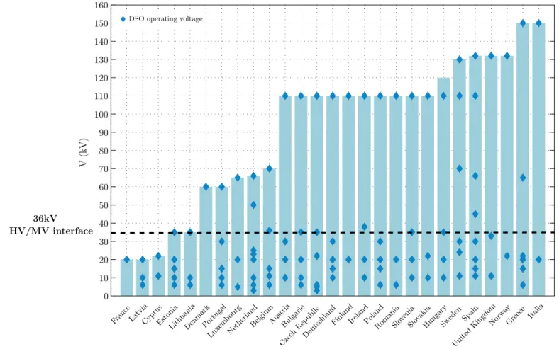
I.3 Comparison of the DSO operating voltages and TSO-DSO interfaces in Europe 12 I.4 Present voltage and reactive power control strategy in French Distribution System . . . 14
I.5 Evolution of the voltages along a distribution feeder without significant pro-duction . . . 15
I.6 Inner control (AVR, Automatic Voltage Regulator) of the OLTC . . . 16
I.7 Evolution of the voltage profile with a CVR scheme . . . 19
I.8 Structure of the three level voltage control in the French transmission system 21 II.1 Location of MV network evolutions and their consequences . . . 25
II.2 Schematic diagram of the DCC requirements regarding reactive power flows at the distribution/transmission system interface . . . 29
II.3 One-line diagram of a simplified system to illustrate the reactive power sup-port from DGs . . . 32
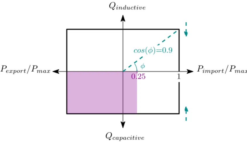
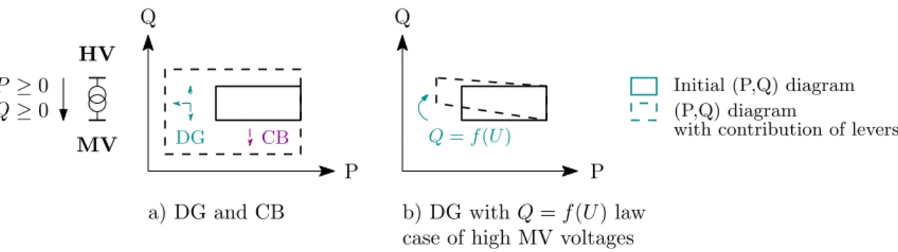
II.4 Schematic (P,Q) diagram of DG connected to the MV network . . . 32
III.1 Proposed evolution of traditional voltage and reactive control strategy in dis-tribution network . . . 37
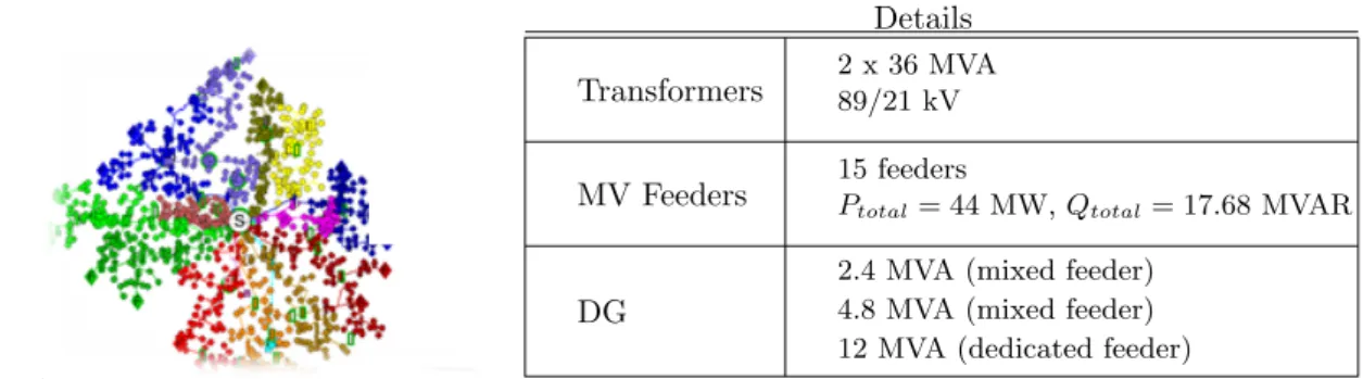
III.2 Schematic of the medium-scale system . . . 39
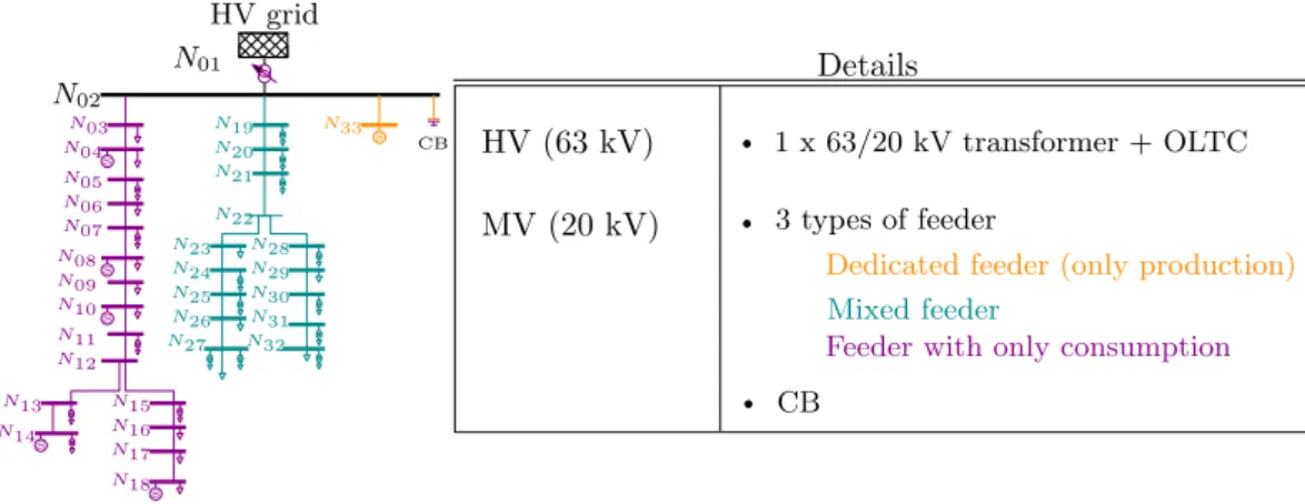
III.3 Presentation of the real french 20 kV grid used in simulations . . . 41
III.4 Presentation of the simplified 20 kV grid used in simulations . . . 42
III.5 Detail of the medium scale system used in simulations: several MV grids connected to a HV grid . . . 43
III.6 Origins of reactive power at the HV/MV grids interface . . . 44
III.7 Origins of reactive power flows at GSP . . . 45
III.8 Coarse evaluation of the DG and CB influence on the (P,Q) diagram of a given substation . . . 47
III.9 10-minutes (P,Q) points of the anonymous substation for summer time . . . 48
III.10 Maximum reactive power from MV to HV networks before OLTC saturation 50 IV.1 From uncoordinated (local) to coordinated control structures . . . 58
IV.2 MPC receding horizon principle . . . 64
IV.4 The OLTC voltage reference rule . . . 71
IV.5 Principle of the Q = f(U) rules . . . 72
IV.6 The reactive power rule . . . 72
IV.7 Control structure of the proposed optimization-based VVC strategy . . . 73
V.1 Schematic of the proposed MPC control structure . . . 83
V.2 Illustration of the exponential convergence for several values of α and β = 0.0001 . . . 85
V.3 Integration of the OLTC actions within the prediction horizon at t = t0 . . . 86
V.4 Three-bus simplified network . . . 92
V.5 Results and control, continuous approximation . . . 93
V.6 Results and control, discrete model . . . 94
V.7 Parametric uncertainties (blue) and external disturbances (magenta) that can affect the VVC controler . . . 97
V.8 Assumptions regarding the (P,Q) diagram of DGs . . . 100
V.9 Production profile for robustness assessment . . . 101
V.10 Loading profile for robustness assessment . . . 101
V.11 Visualization of a noisy voltage measurement . . . 102
V.12 Results and control action, case A, MPC1 . . . 103
V.13 Results and control action, case A, MPC2 . . . 104
V.14 Comparison of DGs reactive power output and DG reactive power reference, case A, MPC1 . . . 105
V.15 Comparison of DGs reactive power output and DG reactive power reference, case A, MPC2 . . . 106
V.16 Results and control action, case B, MPC1 . . . 107
V.17 Results and control action, case B, MPC2 . . . 108
V.18 Comparison of DGs reactive power output and DG reactive power reference, case B, MPC1 . . . 109
V.19 Results and control actions in the 20 kV grid in case of a large HV disturbance 112 VI.1 Results without a VVC . . . 120
VI.2 Results with R-VVC . . . 121
VI.3 Results with O-VVC . . . 123
VI.4 Results with MPC-VVC . . . 124
VI.5 Distribution on the MV voltage constraint violation depending on the control algorithm . . . 126
VI.6 Distribution on the tanHV→MV constraint violation depending on the control algorithm . . . 127
VII.1 Two nodes lines . . . 134
VII.2 High reactive power flowing upwards at EHV/HV interface . . . 135
VII.3 Evolution of the reactive power at EHV/HV interface depending on the load-ing and production scale . . . 137
VII.4 Evolution of the maximal HV voltage depending on the loading and
produc-tion scale . . . 137
VII.5 Practical realization of the dynamic simulations . . . 143
VII.6 State-flow of the proposed reactive power support . . . 145
VII.7 Schematic of the proposed control . . . 146
VII.8 Comparison of the evolution of HV voltages, Case A solid lines and Case B in dotted lines . . . 148
VII.9 Comparison of the evolution of the reactive power flowing through HV/MV transformer at HV side, Case A solid lines and Case B in dotted lines . . . . 148
VII.10 Simulation results for the MV grid downstream T7, case A . . . 151
VII.11 Simulation results for the MV grid downstream T7, case B . . . 152
VIII.1 Schematic of the proposed OPF control strategy . . . 158
VIII.2 Illustration of Iron and Joule losses inside a transformer . . . 161
VIII.3 Principle of the hierarchical relaxation for the OPF resolution . . . 162
VIII.4 Principle of the OPF strategy . . . 163
VIII.5 Total amount of reactive power requested depending on the OPF problem definition . . . 165
VIII.6 Active losses within the medium-scale system depending on the OPF problem definition . . . 166
VIII.7 Association of the OPF strategy with the VVC of distribution grids . . . 168
VIII.8 Evolution of the HV voltages with the association of the OPF-based reactive power strategy and the predictive VVC of distribution grids . . . 169
VIII.9 Evolution of the HV/MV reactive power exchange with the association of the OPF-based reactive power strategy and the predictive VVC of distribution grids170 VIII.10 Focus on the results of the MV grid downstream T2 . . . 171
VIII.11 Evolution of the HV voltages with the proposed reactive power management considering a EHV/HV reactive power limitation . . . 173
VIII.12 Evolution of the reactive power flows within the HV system with the proposed reactive power management considering a EHV/HV reactive power limitation 173 VIII.13 Focus on the results of the MV grid downstream T2 to illustrate the issue of inappropriate tap operations . . . 174
VIII.14 One-Line Diagram of the 3 feeders MV grid . . . 186
VIII.15 Medium scale system combining HV grid and several MV networks, visual-ization of the real 20 kV network topology . . . 191
ADA Advanced Distribution Automation. AVR Automatic Voltage Regulation. CB Capacitor Bank.
CVR Conservation Voltage Reduction. DCC Demand and Connection Code. DG Distributed Generation.
DMS Distribution Management System. DNCC Distribution Network Control Center. DSE Distributed State Estimator.
DSO Distribution System Operator. EHV Extra High Voltage.
Enedis ex ERDF (Electricité Réseau de Distribution France), a French DSO. GSP Grid Supply Point.
HV High Voltage. LV Low Voltage.
MPC Model Predictive Control. MV Medium Voltage.
NLTC No Load Tap Changer. OLTC On Load Tap Changer.
TSO Transmission System Operator. VVC Volt Var Control.
A l’heure où j’écris ces lignes, l’ultime étape de la thèse, je réalise plus clairement que ces travaux sont la somme de contributions diverses et auraient été bien moins aboutis sans toute l’aide que j’ai reçue.
Je voudrais remercier chaleureusement toutes les personnes qui m’ont aidée et soutenue durant ces trois dernières années.
Tout d’abord, je tiens à exprimer ma sincère reconnaissance et mon respect à l’ensemble des membres du jury. Je suis en particulier honorée qu’Yvon Bésanger et Mario Paolone aient accepté d’être les rapporteurs du manuscrit. Je vous remercie pour vos remarques constructives et votre lecture attentive qui a permis d’améliorer le mémoire de thèse ainsi que la présentation des travaux; merci également pour les échanges et commentaires intéressants que nous avons eu lors de la soutenance.
J’adresse également mes remerciements àHervé Lefebvre pour sa présence et ses remarques lors de la soutenance.
Je voudrais ensuite remercier chaleureusementThierry Van Cutsem qui m’a fait l’honneur de présider le jury. Je lui suis par ailleurs redevable pour ses conseils et ses contributions pré-cieuses quant à l’orientation des travaux durant ces trois années, ainsi que ses commentaires et remarques sur le mémoire de thèse.
J’adresse toute ma gratitude àXavier Guillaud, mon directeur de thèse qui m’a fait confi-ance tout au long de la thèse. J’ai vraiment bénéficié de tes conseils notamment pour améliorer la valorisation et la communication des travaux, et j’ai pu apprécié tes qualités pédagogiques et scientifiques.
Je remercie chaleureusementJean-Yves Dieulot dont j’ai particulièrement apprécié les remar-ques et tous les conseils prodigués. Je te suis très reconnaissante pour ton soutien et ton in-vestissement dans mes travaux, ton souci du détail et ta tenacité.
Je voudrais également exprimer ma reconnaissance àSébastien Grenard. Merci pour ton im-plication dans le suivi et l’encadrement des travaux. Merci pour ta disponibilité, et tous tes conseils scientifiques et professionnels. J’ai beaucoup appris du fonctionnement des réseaux de distribution grâce à ton expertise.
Je suis particulièrement reconnaissance à Frédéric Colas sans qui ces travaux seraient bien moins aboutis qu’ils ne le sont aujourd’hui. Merci pour ton encadrement quotidien, tes conseils et ton soutien dans les moments les plus difficiles de la thèse.
Je souhaite également remercierEnedis de m’avoir accueillie à plusieurs reprises au sein du département Politiques et Stratégies, en particulier Jacques Merley, François Blanquet, Pierre
Mallet. Je remercie Michel Albert qui m’a aidée à éclaircir mon projet professionnel. Merci également à Guillaume Pelton, Leticia De Alvaro, François Beauné et toutes les personnes d’Enedis qui m’ont beaucoup apporté sur le fonctionnement des réseaux de distribution et le rôle du gestionnaire.
Au cours de ces trois années de thèse, j’ai eu la chance de rencontrer et de côtoyer les membres des laboratoires LSIS, L2EP, LML, le personnel d’AMVALOR et de l’ENSAM de Lille, les coureurs du jeudi midi... Je voudrais tous les remercier de m’avoir apporté ce cadre de travail chaleureux et enrichissant.
Merci à Pierre, Franck, Nadim, Gil, Pierre, Joris, Manu, Shabab, Julian, David, Tiago, Hus-sein, Thomas, Quentin, Gabriel, Axel, Swan, Jérôme et toute la bande... Vous êtes devenus de vrais amis et je suis déjà nostalgique de ces moments partagés.
Merci également à Héloïse pour tes conseils et tes encouragements, je te suis reconnaissante d’avoir partagé avec moi ton expérience qui m’a aidée à éclaircir mon projet professionnel. Merci à Petros Aristidiou pour ses conseils scientifiques et son aide pour la prise en main de l’outil RAMSES.
Merci à toutes les personnes qui m’ont soutenue et aidée et que je ne peux citer toutes individuellement. Un merci spécial à Elisabeth pour son amitié, ses encouragements et les dîners du mercredi soir.
Mes derniers remerciements vont à ma famille pour tous les moments de bonheur et de partage qui m’ont permis de mener à bien ce projet. Je remercie du fond du cœur mes grand-parents, mes frères Camille et Jean, mes sœurs Adèle et Claire et leur famille qui sont une source de joie et dont le soutien est sans faille. Merci en particulier à mes parents qui m’ont toujours témoigné leur confiance et leur amour et ont su rendre plus faciles ces dernières années.
Thesis Context and abstract
This PhD work has been conducted within the Laboratory of Electrical Engineering and Power Electronics (L2EP) of Lille and in partnership with the major French DSO, Enedis. The objectives defined by Enedis were to quantify how the evolution of the distribution system may impact the voltage control and reactive power management, and more specifically at the interface of High Voltage (HV) and Medium Voltage (MV) systems. Then, several solutions could be proposed and compared to enhance the coordination of voltage control at the HV/MV interface.
Distribution networks are nowadays undergoing major changes that put into question the relevance of traditional voltage control and reactive power management schemes of the electri-cal power system. These changes are namely the massive insertion of Distributed Generation (DG), the replacement of overhead lines by underground cables and the evolution of the load. As a result, distribution networks are prone to an increase of voltage profiles and a change in reactive power flows leading in some situations to reactive power flowing upwards at the dis-tribution/transmission system interface. These flows may impact voltage control and reactive power management strategies on both MV (Medium Voltage) and High Voltage (HV) networks. The coupling between HV and MV systems is thus strengthened: the coupling is more erratic, variable and hardly predictable. Along with this technical evolution, any new distribution system will have to comply with the new regulatory framework defined by the European Grid Codes. More specificaly, in the Demand and Connection code, any new distribution system should be able to restrain the reactive power flowing upwards HV grid at low consumption.
To cope with the new operational concerns and the regulatory framework, there is a need to define new strategies at the interface between transmission and distribution systems. In this work, a strategy based on an evolution of the real-time Volt Var Control (VVC) in distribution system and an increased coordination between Transmission and Distribution System Operators (TSO, DSO) has been developed. With regard to all the aforementioned evolutions, the real-time VVC scheme should be enhanced in order to reach a twofold objective: to improve control of reactive power exchanges between HV and MV grids while maintaining a suitable MV voltage profiles. To this end, three VVC schemes have been developed and compared: a rule-based method, an optimization based method and a Model Predictive Control (MPC) method. These schemes take advantage of the MV network control actions by adjusting in a coordinated manner
the reference of On Load Tap Changer (OLTC), the reactive power of DGs and the number of activated step of Capacitor Banks. The main contribution of the works lies in the definition of the predictive scheme. In short, this scheme is merging MPC with the OLTC inner control algorithm and embeds all of the OLTC nonlinearities. Hence, fundamental modifications of the existing control devices and operating processes are avoided while the minimization of tap change occurrence (and thus the control cost) is accurately limited.
Then, the relevance of a TSO-DSO coordinated reactive power management scheme to main-tain HV voltage and control HV reactive power flows has been further discussed for a medium-scale system, that is a system which encompasses several distribution grids connected to a HV grid. Thus, it is possible to study and take into account both DSO and TSO needs, requirements and constraints. An Optimal Power Flow based strategy has been developed to reach such a coordination that yields the optimal reactive power limitation at the HV/MV interfaces to be enforced. The association of the proposed coordinated management with the real-time VVCs of distribution networks has been more particularly studied.
Thesis organization
The thesis is divided in three parts, split into two or three chapters.
PART A is entitled “Voltage Control in Distribution Networks and Reactive Power Exchange at the Transmission and Distribution System Interface”.
CHAPTER I is dedicated to a general background on electrical power systems and more
specifically on the presentation of the traditional voltage control and reactive power man-agement in the distribution system. The French situation is more particularly explained. The transmission network control schemes are briefly introduced.
CHAPTER II deals with the undergoing changes of distribution systems. The interest of
developing new voltage control strategies for MV network and at the HV/MV systems interface is assessed. Then, the opportunities as well as the technological limitations for voltage control and reactive power management are further discussed.
CHAPTER III gives the motivations as well as the position of our work. In short, the
strat-egy developed is based on an enhancement of the real-time Volt Var Control of distribution networks and on an increased coordination between both Transmission and Distribution System Operators. The scientific approach as well as the tools and networks considered are also detailed in this last chapter of Part A.
PART B is dedicated to the design of an original real-time Volt Var Control for distribution network. Such a control must be compliant with present industrial requirements and able to en-force a suitable MV voltage profile with an appropriate reactive power exchange at the HV/MV system interface.
CHAPTER IV consists of a survey on the real-time VVC of distribution networks. In this
Chapter, the relevance of using centralized strategies based on Model Predictive Control is more specifically assessed. Two standards methods, viz. a rule-based and a one-step ahead optimization based methods, are introduced in this chapter for comparative purposes.
CHAPTER V underlines the methodology used for the design of an original predictive
Volt Var Control. In order to asses the performances of such a control, a robustness study has been designed and performed.
CHAPTER VI gives the results of a comparison based on dynamic simulations of the
proposed predictive controller with the two standard methods introduced in Chapter IV. The results corroborates the relevance of selecting a MPC method for the design of a real-time VVC.
PART C handles the design of joint TSO-DSO reactive power management based on a reactive power support from MV grids.
CHAPTER VII discusses the interest of such a support from the TSO point of view. The
need to perform dynamic simulations, on a a medium scale system combining several MV grids connected to the same HV system is stated.
CHAPTER VIII aims to propose a joint TSO-DSO reactive power management based on
an Optimal Power Flow method. This management addresses the voltage and reactive power requirements of the TSO while considering the limitations of MV grids. The asso-ciation of such coordination with the real-time predictive VVC of distribution networks is studied through dynamic simulations on a medium scale system.
Thesis contribution
The main contributions of this work lie in the design of a real-time VVC for MV grids and a joint DSO-TSO reactive power management.
Regarding the real-time VVC for MV grids, the key-features of the proposed approach are: • To propose a coordination of many actuators for voltage regulation and reactive power
exchange at TSO/DSO interface;
• To show the relevance of considering MPC-based methods for the design of the control law and proposal of methods to assess the performances of such a control;
• To guarantee the minimization of tap changes during all life of the OLTC since the crite-rion is explicitly considered in the cost function;
• To keep and consider the classical OLTC inner control to avoid fundamental modifications of the existing control devices and operating process.
On the other hand, for the joint reactive power management, there are some points that should be more specifically considered. Due to the cross interactions between MV and HV grids, a coordination among these grids should be considered to develop an appropriate and ef-ficient reactive and voltage control at the interface between HV and MV systems. In our work, the TSO was assumed to be responsible for this coordination that is yet jointly designed with the DSO. A control located within the Transmission Network Control Center was proposed. Since the control was designed for a specific system and under specific circumstances, the re-sults are not to be generalized. However, these rere-sults enable to draw conclusions and give
recommendations for the design of a suitable TSO/DSO coordination. As a reminder, such a co-ordination should tackle the voltage and reactive power concerns at TSO/DSO systems interface while using a support from MV grids:
• Connections and network planning studies should be jointly performed by TSO and DSO to ensure that the objectives of the control are relevant and achievable;
• Real-time management of reactive power within a HV grid should result from a optimum of reactive power resources of TSO and DSO. Optimal Power Flow based solutions are of interest to handle the design of such a solution;
• Dynamic simulations should be performed on a medium scale system in order to take into account the true behavior of MV and HV grids and their own control;
• Relevant information to be exchanged by TSO and DSO should be identified. More espe-cially the real-time reactive power reserve at the interface should be exchanged between the TSO and the DSO.
A general conclusion summarizes the main recommendations and opens the work towards new research studies.
Thesis publications
Conference publications• J.Morin, F.Colas, X. Guillaud, and S. Grenard, “Determination and origins of a reactive power flows in HV/MV substations”, in 23rdInternational Conference and Exhibition on
Electricity Distribution (CIRED 2015), Lyon, 2015.
• J.Morin, F.Colas, X. Guillaud, S. Grenard and J.Y. Dieulot, “Rules based voltage control for distributions networks combined with TSO-DSO reactive power exchange manage-ment”, in IEEE Eindhoven Powertech, Eindhoven, 2015.
• J.Morin, F.Colas, X. Guillaud, S. Grenard and J.Y. Dieulot, “Coordinated predictive con-trol in active distribution networks with HV/MV reactive power constraint”, in IEEE PES Innovative Smart Grid Technologies (ISGT) Europe, 2016, Accepted for an oral presenta-tion.
Journal publications
Submitted:
• J.Morin, F.Colas, X. Guillaud, S. Grenard and J.Y. Dieulot, “Embedding OLTC nonlin-earities in predictive Volt Var Control for active distribution networks”, Electrical Power System Research, Submitted in May 2016, accepted for publication.
• J.Morin, F.Colas, X. Guillaud, S. Grenard and J.Y. Dieulot, “Coordinated predictive con-trol of active distribution networks to help transmission system in emergency situation”, Sustainable Energy Grids and Networks, Submitted in July 2016, under review.
Voltage Control in Distribution
Networks and Reactive Power
Exchange at the Transmission and
Existing control and structure of
electricity power system networks
Introduction
Voltage control is of paramount importance to ensure a secure and reliable operation of the electrical power system. This control aims to maintain the voltage level within an acceptable voltage range in compliance with normative requirements. Indeed excessive voltages can be harmful for the networks components and equipment while low voltages may lead to equipment malfunctions. This can be achieved by properly managing the reactive power especially in trans-mission system. Transtrans-mission System Operator (TSO) and Distribution System Operator (DSO) are more specifically responsible for voltage control for their own network.
The scope of this chapter is to recall the traditional voltage control and reactive power man-agement strategy in the electrical system, more especially in the distribution system and at the interface between transmission and distribution grids. After a brief description of the power system and the role of system operators (See section I.1), the traditional control strategies are presented in section I.2.
Transmission Substransmission HV/MV substation EHV/HV substation MV/LV substation Distribution Transformer OLTC transformer Autotransformer Feeder 36kV 1kV
I.1 Public Electricity Distribution Networks
I.1.1 General structure of electricity power systemsElectrical power systems are traditionally divided into three main layers that are operated at different voltage levels [1] as illustrated in Figure I.1:
• Transmission at Extra High Voltage (EHV) level; • Subtransmission system at High Voltage (HV) level;
• Distribution system at Medium Voltage (MV) and Low Voltage (LV) levels;
According to the European standardisation bodies, the HV level is above 36 kV while MV is in [1 − 36] kV and LV below 1 kV. Figure I.3 gives the voltage level of European MV networks. The EHV grid is the backbone of the electrical system and hosts most of the large power plant units such as nuclear power, hydroelectric or fossil plants. The EHV grid is a long-distance bulk network connected to the HV grid through EHV/HV stations where the voltage is stepped up by transformers.
The role of the subtransmission system is to convey the electricity from the transmission to the distribution systems and to major industrial loads. Usually, transmission and subtransmission networks are associated, and the transmission system term encompasses both transmission and subtransmission grids.
The HV power is converted in the HV/MV substations corresponding to physical boundaries between the subtransmission and distribution systems. At the final stage of the electricity net-works, the distribution grids are designed to deliver electricity to the end users. Generally, the distribution systems are subdivided into two levels: MV and LV grids. Medium size industrial loads and distributed generators are connected to the MV level, while downstream MV/LV sub-stations, commercial and residential consumers are connected to the LV feeders as well as small distributed generators.
The French MV distribution grid is made of 2 240 HV/MV substations, 1.3 million kilome-ters of lines and underground cables, and 751 000 MV/LV substations1. In addition to these
physical elements, there are 30 Distribution Network Control Centers in France responsible for the secure operation of a given regional area and hosting the distribution management tools (such as Distribution Management System (DMS), Advanced Distribution Automation (ADA), Distributed State Estimator (DSE)...). 232 636 production sites are connected to the distribution system.
As in most of European countries, French distribution grids are organized as rings but oper-ated as radial networks. The radial structure is indeed optimal for maintenance purposes, fault detection and eases protection strategies.
I.1.2 Public electricity distribution networks in France 400V 20kV 225kV 400kV LV MV HV EHV Distribution Transmission 90kV 63kV
Figure I.2: Voltage levels in France
In France, most of the distribution networks are owned by the local authority. The MV network supplies the voltage at 20kV, while the LV networks supplies the voltage at 400V as given by Figure I.2.
A classical MV distribution network consists of:
• HV/MV substations that generally include several transformers with On Load Tap Changer, and in some of them, a Capacitor Bank (CB) is connected to the MV busbar of the HV/MV substations;
• MV customers, such as small industrial loads, the MV/LV substations or DGs, if the maximal active power is below 12 MW2;
• MV feeders (namely the overhead lines and underground cables), that can be further clas-sified in three categories:
· Dedicaded feeder: a feeder hosting only a DG, · Mixed feeder: a feeder with both DGs and loads, · Other feeder: with only loads.
The LV grids are made of:
• MV/LV susbtations equipped with transformers;
• LV customers (namely loads and DGs with a maximal nominal power below 250 kVA); • LV feeders.
I. EXISTING CONTR OL AND STR UCTURE OF ELECTRICITY PO WER SYSTEM NETW 0 10 20 30 40 50 60 70 80 90 100 110 120 130 140 150 160 V (kV)
France LatviaCyprusEstoniaLithuaniaDenmarkPortugal Luxem
bourg
NetherlandBelgiumAustriaBulgarie Czec
hRepublicDeutsc
hlandFinlandIrelandPolandRomaniaSlovenia
SlovakiaHungarySweden Spain United KingdomNorw ay Greece Italia 36kV HV/MV interface
DSO operating voltage
Figure I.3: Comparison of the DSO operating voltages and TSO-DSO interfaces in Europe
I.1.3 Distribution and Transmission system operators
Transmission System Operators (TSOs) and Distribution System Operators (DSOs) are responsible for a secure and reliable operation of the power system. More specifically TSOs are entrusted for "operating and insuring the maintenance of and, if necessary, developing the transmission system in a given area and, where applicable, its interconnections with other sys-tems, and for ensuring the long-term ability of the system to meet reasonable demands for the transmission of electricity" as defined by the directive 2009/72 of the European Commission. Accordingly, DSOs are responsible for the distribution of electricity.
In France, the electricity distribution is a regulated activity supervised by the French Energy Regulator (CRE). Enedis is entrusted to manage around 95 % of the French public electricity network through a public service delegation. Enedis should thus fulfill a twofold mission: ensure service continuity and quality of supply, and provide a non-discriminatory access to the network. It should be borne in mind that the voltage levels area managed by the European Distribution System Operator (DSO) is not the same as shown in Figure I.3. Hence, the role of the DSO is quite different from a country to another. Nonetheless, a DSO is more specifically responsible for maintaining the MV and LV voltages within acceptable ranges of values for a secure and reliable grid operation.
In France, this specified range comply with standards (EN 50-160), legal (according to the 2007-1826 decree) and contractual (contract for access to the distribution system) requirements. To meet these requirements, the LV voltages should be maintained in normal operating condi-tions around ±10% of the nominal value at the connection point. As for the MV voltages, they should stay within ±5% of a contractual voltage value, that is around ±5% of the nominal value at the connection point. This requirements should be enforced 95% of the time, by steps of 10 minutes for a week.
Besides, in network planning studies, Enedis makes sure that the voltage rise does not overshoot 2%in mixed feeder and 7% in dedicated feeder, while the voltage drop is limited to 5%.
I.2 Current practices of Voltage Control and Reactive Power
Man-agement in Distribution and Transmission Grids
This section aims to present traditional voltage control and reactive power management schemes. The French case is more specifically enlightened.
I.2.1 Control strategy at the distribution level
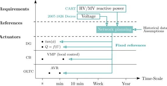
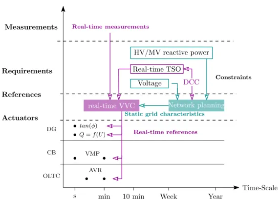
In short, the main concern of the voltage and reactive power control strategy is to comply with normative, legislative and contractual requirements. To this end, Enedis has set up industrial policies that are mainly based on network planning studies and the use of On Load Tap Changers (OLTC), No-Load-Tap-Changers and CBs. These studies specify the network reinforcement needs and set the local control of dynamic actuators as illustrated in Figure I.4:
• The voltage reference of the OLTC inner control; • The power factor (tan(φ)DG) or Q = f(U) law of DG;
• The Var-Metric-Process (VMP) e.g. the on/off switching rule of CBs.
Then, the Automatic Voltage Regulation (AVR) (namely the OLTC inner control) automatically controls the MV voltage profile while the VMP of CB adjusts the reactive power at HV/MV systems interface for winter time to enforce legal (2007-1826 Decree) and contractual (contract to access to the transmission system, CART) requirements.
min
s 10 min Week Year
tan(φ) Q = f (U ) VMP (local control) AVR OLTC CB DG Voltage Historical data Assumptions HV/MV reactive power Requirements References Actuators Network planning Fixed references 2007-1826 Decree CART Time-Scale
Figure I.4: Present voltage and reactive power control strategy in French Distribution System I.2.1.a Voltage and reactive power control in France
To maintain an acceptable voltage profile, Enedis mainly uses On Load Tap Changer (OLTC) in HV/MV substations and No Load Tap Changer (NLTC) in MV/LV substations described in
Table I.1. For both the OLTC and NLTC, the principle is to step down the voltage by changing the ratio of the transformer thanks to a variable number of winding turns. The evolution of the voltage profile along a distribution feeder without significant DGs production is depicted in Figure I.5.
OLTC and NLTC to adjust the voltage
Some turns in the windings of the MV/LV transformer can be either added or removed manually from the main winding. Generally, MV/LV NLTC have three positions to adjust the voltage by step of 2.5 %. Since, this adjustment must realized off-load, the position of the NLTC is infrequently updated (for instance during maintenance works).
Nowadays, Enedis is performing advanced R&D works on smart MV/LV substation and more specifically on a smart MV/LV transformer [2].
HV HV/MV substation LV feeder MV/LV substation MV feeder 1 pu +5 % −5 % +10 % −10 % Vend user Feeder VM V VLV
Figure I.5: Evolution of the voltages along a distribution feeder without significant production
Table I.1: Existing levers for voltage control in French distribution networks
Levers Location Details Control
OLTC HV/MV substations 17, 21 or 23 steps Automatic control ±14% or ±12%
NLTC MV/LV substations [+0%, +2.5%, +5%]3 steps Off-loadManual
OLTCs are of paramount importance for voltage control in radial distribution networks. Their principle is to maintain the voltage at the secondary side of a transformer by automati-cally adjusting the ratio r = VHV
VM V by discrete step corresponding to a change of tap nOLT C
according to an inner control (generally called Automatic Voltage Regulator) algorithm as il-lustrated in Figure I.6 [3, 4]. Their aim is to partially decouple the MV voltages from the HV voltages.
VM V VHV PM V→HV QM V→HV VM V(t) VOLT C ref(t) ∆V (t) ∆nOLT C(t)
OLTC inner control nOLT C(t) nOLT C(t) Dead-band 1 −1 0 e ∆V d −d Time-delay 0 τ t 1 1 −1 0
Figure I.6: Inner control (AVR, Automatic Voltage Regulator) of the OLTC
The AVR continuously monitors the voltage at the secondary side of the transformer VM V.
If the difference between the voltage reference VOLT Crefand this voltage VM V exceeds the half
dead-band d for a time longer than the time-delay τ, a change of tap is triggered. Each change of tap generates a change in voltage Vtapat the secondary side. The dead-band 2d is classically
chosen equal to this voltage change: 2d = Vtap. In practice, this value is around 1 − 1.5 % and
there are 17 tap positions.
This industrial control system has been designed to optimize the life span of the OLTC. For instance, the dead-band and the time-delays have been chosen to avoid excessive switching that can cause an early wear. In France, time-delays are of 60 s for the first tap change and 10 s for subsequent tap changes and are consistent with the EHV/HV OLTC time-delays.
Reactive power compensation using CBs
In distribution systems, there is no close relationship between the voltage and the reactive power contrary to the transmission grids. However, reactive power is necessary for a proper operation of the system to maintain the transmission voltages close to their nominal values, reduce the line currents (and hence the losses) or for stability purposes [3, 5]. This compensation should be done locally to avoid large power flows and to relieve the transmission system during peak load conditions.
The easiest and common mean of reactive power compensation is the use of Capacitor Banks. In France, CBs have been mainly connected to the MV busbar of the HV/MV transformers to compensate for the loads connected to the MV and LV feeders.
Table I.2 gives the main reactive power levers in use in the French distribution networks. By comparison, the reactive power compensation in transmission system is far more developed. There are for instance dynamic devices such as the FACTs or synchronous compensators that could be potential levers for distribution systems as well. Next, shunt reactance are connected to certain EHV/HV stations and can be automatically switched off/on from the Transmission Network Control Center.
Table I.2: Existing levers for reactive power compensation in French distribution networks
Levers Location Details Control
CB HV/MV substations 3 steps · VMP
1.2to 1.8 MVAR · manual Enedis industrial policies
Enedis policy is a traditional voltage control strategy based on solutions such as grid rein-forcement or "fit and forget" design approaches. Any new equipment to be connected to the grid is sized to prevent over or under voltage in the most critical situations (namely high consumption with no production and low consumption with high production cases) during network planning studies.
Since the distribution systems were designed to deliver the power to the end users, only unidi-rectional flows (from upstream to downstream) were considered. The voltage control methods were set up to mitigate the voltage drop along the distribution feeders by means of transformers. The maximal voltage drop should not overshoot 5% in normal operating conditions, and 8% in emergency situations.
i) Normal operating conditions: The insertion of DGs has made more complicated the voltage control policies. Traditionally, a compounding technique was used [6] in France for the OLTC. This technique consists in adjusting the voltage reference depending on the current flowing trough the transformer that was reflecting the level of consumption in the MV feeders:
VOLT Cref= Vnom+ kI. (I.1)
Where Vnom is the nominal MV voltage, typically 20 kV. However, due to the insertion of
the DGs in the distribution networks, this current does not reflect anymore the true level of consumption (and thus the voltage drop along the feeder) and this technique had to be dropped off. New policies have been set up to ensure that DGs can be connected to the distribution networks without inducing over-voltages:
• VOLT Cref + 4%for a feeder without a significant amount of production,
• VOLT Cref + 2%for a feeder with a high amount of production to prevent over-voltages.
For some substations embedding numerical control law technologies, it is possible to dy-namically adjust the voltage reference through a remote control system within the range [Vnom+
2%, Vnom+ 4%].
Nowadays, the DGs do not take part in the reactive power compensation scheme, but their reactive power can be used as an alternative to grid reinforcement to limit their connection costs. To this end, for the DGs connected in a mixed MV feeder, the power factor tan(φ)DG = QPDGDG
is specified in the following range according to the decree of 23 April 20083
tan(φ)DG∈ [−0.35, +0.4] (I.2)
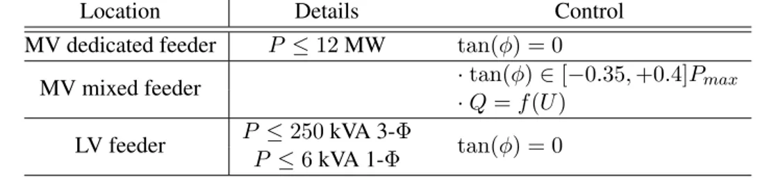
This value is defined in network planning in order to ensure that even in the most stressed condi-tions (namely high loading associated with no generation and low loading with high generation), the MV voltages remain within the contractual range of values. The network planning processes are further described in [7]. For the DGs connected to LV feeders or dedicated MV feeders, the tan(φ)DGis set up to zero. Table I.3 summarizes the reactive power compensation of DGs
connected to the French distribution grid.
It could be noted that, given the relationship between voltage and reactive power, the DGs connected to mixed MV feeders can be seen somehow as a voltage control lever. In fact, it is an alternative to grid reinforcement to minimize the DGs connection cost and not a voltage control lever.
Yet, Enedis has designed a law Q = f(U) that modulates the reactive power of DGs depending on the voltage at their point of connection. This law will be more specifically detailed in Part B. Q = f (U )laws have the very same purpose than a constant power factor (tan(φ)DG) operation
of DG. However, the main advantage of such laws is to avoid requesting reactive power when unnecessary. The reactive power is called for only if there is an overshoot of the voltage at the DG connection point. Yet, this implies that the reactive power cannot be used for another purposes than the local control of the voltage at this DG point of connection.
Table I.3: Reactive power compensation of DGs connected in the French distribution grid
Location Details Control
MV dedicated feeder P ≤ 12 MW tan(φ) = 0
MV mixed feeder · tan(φ) ∈ [−0.35, +0.4]Pmax
· Q = f(U) LV feeder P ≤ 250 kVA 3-Φ tan(φ) = 0
P ≤ 6 kVA 1-Φ
Regarding reactive power compensation, historically, the off/on switching of the CB steps was done following a seasonal schedule set up according to the consumption pattern. With the evolution of the loads and the insertion of DGs, one is able to understand the limitation of such a procedure. Nowadays, substations are equipped with a VMP (Var Metric Process) controller responsible for the automatic switching of the CB steps. The control law is detailed in [6].
ii) Emergency situations: During emergency situations, the OLTC voltage reference can be lowered or the tap changer can even be blocked by a special request of the TSO from the Transmission Network Control Center sent to the Distribution Network Control Center.
Moreover, if the OLTC has been deactivated after a TSO request, the CB switching are also disabled to prevent a further degradation of the situation.
To sum up, the industrial policies set up by Enedis aim to maintain the MV and LV voltages in the required range of values to ensure a high quality of supply for the final customers (that can be either a load or a production site). This strategy should be able to deal with an increased penetration of DGs in the distribution grids. Indeed, such an increase should be expecting ac-cording to the European objectives on DGs connection. These objectives purposes are to raise
the share of renewable energy sources in the energy consumption up to 20% from 2020 and 27% by 2030.
In other countries, energy saving and efficiency are targeted. In this case, Conservation Voltage Reduction (CVR) strategies are developed. Such strategies are briefly introduced and discussed hereafter.
I.2.1.b Conservation Voltage Reduction schemes
Conservation Voltage Reduction (CVR) is a technology that was developed in the 1950s and is commonly used in United States, Canada, Australia or Ireland. The main concern of this technique lies in increasing energy efficiency by lowering as much as possible the voltage downstream the HV/MV substations [8]. Indeed depending on the load types (mainly the load to voltage relationship), lowering the voltage will turn in lowering the power consumption. This very simple principle is also used to reduce the the consumption during peak conditions. Concretely, CVR can be achieved through several methods [8, 9]. The most employed solution is based on a coordination between OLTC and the off/on switching of CB connected throughout a MV feeder. The voltage reference is lowered as much as possible while the CBs are used to flatten the voltage profile along the feeder as shown in Figure I.7.
HV HV/MV substation LV feeder MV/LV substation MV feeder Vend user Feeder VM V VLV
Figure I.7: Evolution of the voltage profile with a CVR scheme
However, there are still some limitations to expand the implementation of CVR, especially in France:
• Poor quality of supply (due to low voltage operating conditions);
• Technical difficulty: coordination of several actuators connected throughout the MV/LV feeders;
• Influence of the massive insertion of DGs on the CVR scheme. For instance wind turbines can induce fast and large voltage variations.
• Difficulty to estimate the true gain yielded by such a method, that mainly depends on the type of load but can also have an impact on losses. A major uncertainty lies in the load to voltage relationship. CVR method has little relevance for constant power loads or for loads with a "rebound" effect. In France, when diminishing the OTLC voltage reference
by 5% after an emergency request from the TSO, a significant growth in consumption is generally observed after a temporarily reduction;
• CVR is designed for networks with a specific topology, more specifically for distribution systems that exhibit long MV feeders with CBs connected throughout the grid and short LV feeders. In France, the LV feeders can be widespread particularly in rural areas, and the voltage drop may be quite large. Next, the CBs are only connected at the secondary side of the HV/MV substations.
I.2.2 Control strategy at the transmission/distribution system interface in France
The link between TSO and DSO is defined by the 6 October 2006 Decree4. This decree
stip-ulates that the TSO and DSO should act in an coordinated manner to ensure the secure operation of the system. To this end, both voltage and reactive power management control are mandatory objectives.
In fact, the TSO-DSO link is mainly contractual as defined by the CART (Contract for Access to the Transmission System). In this document, the value of the power factor at the point of con-nection (i.e. the interface between transmission and distribution system) is specified. This value should not exceed a threshold limit defined for a given area that is supposed to be electrically homogeneous. There are two types of zones, either "green" or "red" associated with different range of values [10].
The performance monitoring consists in checking that the tanHV→MV monthly mean values at
the point of coupling by step of 10 minutes remain within the specified range only during the winter period (from 1stNovember to 31 March), between 6 − 22h.
Moreover, the TSO can send special requests to the DSO during emergency situations as aforementioned. These requests can for instance correspond to:
• A decrease by 5 % of the OLTC voltage reference to temporarily reduce the load demand, • A deactivation of the OLTC of HV/MV substation in order to prevent voltage collapse, • A load shedding of MV feeders.
I.2.3 Control strategy at the transmission level in France
I.2.3.a 3-level voltage control in EHV
In EHV voltages, the lines reactive impedance is around ten times the lines resistance. As a result, there is a strong link between reactive power and EHV or HV voltages. An inappropriate reactive power flow in the network would result in unsuitable voltages. Also, to maintain the voltage profile in the network, the TSO should ensure that enough reactive power is available. To this end, the TSO can use several devices which can be either static (such as shunt, CB, FACTs) or dynamic (synchronous generators, generators). The main devices used in France are given in Table I.4.
In France, as in other countries, EHV voltage control has been organized in three levels [11] by RTE (Réseau de Transport d’électricité, the French TSO). The classification is made depending on the time response and the geographical areas.
The Primary Voltage Control (PVC) automatically adjusts within a few seconds the reactive power output of the generators or synchronous generators by controlling the excitation system (Vexc). This control aims to enforce a specified voltage profile. The Secondary Voltage Control
(SVC) supervises this voltage profile: the reactive power resources (Qref) are coordinated to
maintain the voltage at specified pilot nodes. A pilot node is supposed to embody the voltage level of a regional area. Each area is assumed to be electrically homogeneous and independent from other areas. The SVC is thus decentralized.
RTE has designed a Coordinated SVC (CVSC) [12] to enhance the SVC by taking the interac-tions between the regional areas into account.
The Tertiary Voltage Control (TVC) is a manual control and consists of the dispatching center actions that coordinate the SVC and CSVC voltage profile (Vpilot).
The overall structure of such a hierarchical control is given in Figure I.8.
PVC SVC TVC Time-scale Geographical area National Regional Local s min h PVC generator TVC Vexc Vpilot Qref SVC
Figure I.8: Structure of the three level voltage control in the French transmission system
Table I.4: Reactive power devices used in France
Devices Types Details
Generators Dynamic Automatic control (PVC) Synchronous Generators Dynamic Automatic control (PVC),
only one in France Shunt reactance, CB Static Modify the network
char-acteristics
FACTs Static Modify the network char-acteristics, few in France
I.2.3.b Voltage Control in HV systems
In French HV system, the voltage control is quite coarse compared to the EHV voltage control. It is performed through EHV/HV OLTC. The voltage reference can be remotely adjusted to Vnom+ 1%, Vnom+ 2,5% or Vnom+ 5%.
The reactive power regulation imposed at the HV/MV interface are incentives to maintain the power factors of distribution networks as closed as possible to the unity.
Conclusion
Traditional methods for voltage control and reactive power management at the HV/MV systems interface have been introduced. In distribution systems, even with a presence of Dis-tributed Generation, such a control is mainly achieved through network planning studies that are based on "fit and forget" solutions. These control methods aim to define among others a specified reference to feed the local control of dynamic actuators (viz. On Load Tap Changer, Distributed Generation and Capacitor Bank) as illustrated in Figure I.4. These actuators ex-hibit distinct dynamics. DGs local control act within a few second, while the OLTC embeds time-delays (traditionally of 60s and 10s).
However, some distribution grids are facing major changes that are both technical and reg-ulatory. Chapter II is dedicated to the presentation of these changes. As a consequence, the relevance of the traditional control methods is to be questioned while the interest of using active control scheme is raised.
Bibliography
[1] P. Kundur, N. J. Balu, and M. G. Lauby, Power system stability and control. McGraw-Hill New York, 1994, vol. 7.
[2] C. Guillaume, F. Gaillard, M. Cordonnier, M. Mouhamad, M. Habja, F. Montel-Ragu, and F. Lemenager, “Toward a new generation of secondary substations on french distribution networks to accommodate smart grid requirements,” 23rd International Conference and Exhibition on Electricity Distribution (CIRED 2015), 2015.
[3] T. Van Cutsem and C. Vournas, Voltage Stability of Electric Power Systems. Boston: Springer US, 1998.
[4] M. Calovic, “Modeling and Analysis of Under-Load Tap-Changing Transformer Control Systems,” IEEE Transactions on Power Apparatus and Systems, vol. 7, pp. 1909–1915, 1984.
[5] RTE, “Mémento de la sûreté du système électrique,” Tech. Rep., 2004.
[6] J. Favraud, Fonctionnement et protection des réseaux de distribution, EDF-GDF, Ed. Cen-tre de formation des Mureaux, 1979.
[7] ERDF, Direction Technique, “Étude de l’impact sur la tenue thermique et sur le plan de tension des ouvrages en réseau pour le raccordement d’une production décentralisée en HTA,” ERDF, Tech. Rep., 2016.
[8] Z. Wang and J. Wang, “Review on implementation and assessment of conservation voltage reduction,” Power Systems, IEEE Transactions on, vol. 29, no. 3, pp. 1306–1315, 2014. [9] K. L. Warner and R. Willoughby, “Conservation voltage regulation: An energy efficiency
[10] RTE, “Documentation technique de référence, chapitre 4 - contribution des utilisateurs aux performances du rpt, article 4.2.2 réactif ´r l’interface des gestionnaires de réseaux publics d’électricité,” RTE, Tech. Rep., 2010.
[11] O. A. Mousavi and R. Cherkaoui, “Literature survey on fundamental issues of voltage and reactive power control,” Ecole Polytechnique Fédérale de Lausanne: Lausanne, Switzer-land, 2011.
[12] H. Lefebvre, D. Fragnier, J.-Y. Boussion, P. Mallet, and M. Bulot, “Secondary coordinated voltage control system: feedback of EDF,” in IEEE Power Engineering Society Summer Meeting, vol. 00, no. c, Seatle, 2000, pp. 290–295.
Recent technical and regulatory
transformation of distribution
networks: a need for a new solution
ContentsI.1 Public Electricity Distribution Networks . . . 10 I.1.1 General structure of electricity power systems . . . 10 I.1.2 Public electricity distribution networks in France . . . 11 I.1.3 Distribution and Transmission system operators . . . 13 I.2 Current practices of Voltage Control and Reactive Power Management in
Distribution and Transmission Grids . . . 14 I.2.1 Control strategy at the distribution level . . . 14 I.2.1.a Voltage and reactive power control in France . . . 14 I.2.1.b Conservation Voltage Reduction schemes . . . 19 I.2.2 Control strategy at the transmission/distribution system interface in
France . . . 20 I.2.3 Control strategy at the transmission level in France . . . 20 I.2.3.a 3-level voltage control in EHV . . . 20 I.2.3.b Voltage Control in HV systems . . . 21 Bibliography . . . 22
Introduction
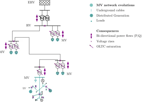
In the last decades, the distribution networks have been undergoing major changes that put into questions the relevance of traditional voltage control and reactive power management schemes. These changes are namely the massive insertion of Distributed Generation (DG), the replacement of overhead lines by underground cables, the evolution of the loads... The place where the network changes are occurring and the main consequences are depicted in Figure II.1. As a result, distribution networks are facing an increase of their voltage profiles and could also face difficulties to limit the reactive power flowing upwards at the distribution/transmission system interface in case low loading. These flows may, in turn, impact voltage and reactive power management in High Voltage networks. The coupling between HV and MV systems is thus more erratic, variable and hardly predictable.
Along with these technical evolutions, any new distribution system must also comply with the recent regulatory framework defined by the European Grid Codes. More particularly, in the Demand and Connection Code (DCC), any new distribution system should be able to restrain the reactive power flowing between TSO-DSO networks at times of low consumption.
To cope with the new operational concerns and the regulatory framework, there is a need to define new strategies at the interface between transmission and distribution systems.
In section II.1,the undergoing changes of distribution systems and subsequent consequences are investigated. Then, in section II.2, opportunities and possible technological limitations for voltage control and reactive power exchange management in distribution networks are further discussed. MV EHV HV MV MV MV S S S S S MV network evolutions Underground cables Distributed Generation Loads
Bi-directional power flows (P,Q) Voltage rises
OLTC saturation Consequences
LV
II.1 Issues raised by the recent developments in the distribution
grid and the new regulatory standards
In this section, we will more specifically introduce the distribution system developments and the subsequent issues (illustrated in Figure II.1) regarding voltages and reactive power flows. In short, the consequences are voltage rises at the MV and HV level, the saturation of HV/MV OLTC, and the difficulty to manage reactive power flows. As a result, the interactions between HV and MV grids are more erratic and exhibit a high variability.
II.1.1 Consequences of distribution networks transformation
II.1.1.a The massive insertion of DGs
Since mid 2000s, a massive insertion of DGs in the distribution networks occurred. As a reminder, a DG is, according to the definition presented by T. Ackermann: " an electric power source connected directly to the distribution network or on the customer site of the meter" [1]. This development was strongly supported by European and French policies and incentive rates for "green" energy. However, this massive integration has repercussions on the electricity net-works.
First, the assumption of unidirectional power flows is no longer valid. Without being ex-haustive, the following consequences can be recalled [2–6]:
• Local impacts:
· Impact on protection plans, no detection of islanding operations that can jeopardize technicians;
· Impact on voltage quality and in particular for DC technology whom power elec-tronic devices generate harmonics. These harmonics may distort the signal called TCFM (remote control musical frequency) used in France to automatically change rates from normal to peak load tariffs,
• More global impacts:
· Impact on the overall stability of the network with an intermittent and stochastic power injection that changes the dynamic of the network,
· Impact on congestion management · Impact on losses...
More specifically, focusing on voltages and reactive power:
• Impact on voltage profile: the presence of DGs can cause rises even at low level of pene-tration. Indeed, with the active power injection, the voltage increases at the point of DG connection and in the DG vicinity.
• Impact on the active/reactive flows that become more and more unpredictable, and that can be reversed at HV/MV substations. In the usual case of weather-dependent DGs, there are intraday fluctuations (day/night for PV) and even faster fluctuations (hourly).
This change in production patterns has repercussions on the DSO and TSO operations (voltage, balancing...). For instance, this reduced observability on the load downstream HV/MV transformer has among others forced to give up on the compounding technique (presented in I.2.1.a) used to tune the HV/MV OLTC voltage reference.
Another issue concerns the size of the DGs. Indeed, due to their small size, it is usually not cost efficient to observe and hence to control them for the DSO. In France, the connection of any DGs with a power injection capacity above 36 kVA implies a complete network planning to determine the possible consequences on the network (namely the voltage profile) and whether a grid rein-forcement has to be performed. Such a reinrein-forcement may require a significant investment. On this other hand, if the reinforcement is not achieved, a saturation of the network hosting capacity may occur [7]. Next, beyond a certain penetration level of small DG units around a given local area, a saturation of this area hosting capacity can happen. As a result, reinforcement may be required.
In order to keep increasing the level of DGs penetration in the distribution networks at low cost without jeopardizing the DSO and TSO operations, innovative solutions need to be found. These solutions should address the concern of voltage rises as well as the active and reactive power flows variability and uncertainty.
II.1.1.b The replacement of overhead lines by underground cables
For several years, overhead lines have been replaced by underground cables. Such a replace-ment was motivated by reliability concerns but also for maintenance purposes There also exists a strong public opposition to overhead lines. Indeed, it was frequent in rural areas that a tree falling on a overhead line causes a power cut and damages the quality of supply. As a result, in France, around 39% of the MV networks and 35 % of the LV grids conductors are underground cables.
Table II.1: Typical MV lines and cables parameters
Conductor Details X R C Snat
(Ω/km) (Ω/km) (nF/km) (MVA)
Overhead 752Almelec 0.35 0.44 5 0.845
Lines 1482Almelec 0.35 0.22 5 0.845
Underground 952Alu 0.13 0.32 177 8.33
Cables 1502Alu 0.13 0.206 250 10
However, this change deeply modifies the reactive power flows in the network. Indeed, depending on its loading level, a given conductor (either a line or a cable) would not exhibit the same reactive behavior. Let Snat be the natural power of a line, that is to say the power
consumed by a line when loaded under its characteristic impedance Zc'
q L C [8]: Snat = 3VnomI = Unom2 Zc . (II.1)