UNIVERSITÉ DE MONTRÉAL
A FUNCTIONAL REASONING FRAMEWORK AND DEPENDENCY MODELING SCHEME FOR MECHATRONICS CONCEPTUAL DESIGN SUPPORT
ELIE HADDAD
DÉPARTEMENT DE GÉNIE MÉCANIQUE ÉCOLE POLYTECHNIQUE DE MONTRÉAL
MÉMOIRE PRÉSENTÉ EN VUE DE L’OBTENTION DU DIPLÔME DE MAÎTRISE ÈS SCIENCE APPLIQUÉES
(GÉNIE MÉCANIQUE) DÉCEMBRE 2015
UNIVERSITÉ DE MONTRÉAL
ÉCOLE POLYTECHNIQUE DE MONTRÉAL
Ce mémoire intitulé:
A FUNCTIONAL REASONING FRAMEWORK AND DEPENDENCY MODELING SCHEME FOR MECHATRONICS CONCEPTUAL DESIGN SUPPORT
présenté par : HADDAD Elie
en vue de l’obtention du diplôme de : Maîtrise ès sciences appliquées a été dûment accepté par le jury d’examen constitué de :
M. BARON Luc, Ph. D., président
M. ACHICHE Sofiane, Ph. D., membre et directeur de recherche M. LAKIS Aouni, Ph. D., membre et codirecteur de recherche M. RAISON Maxime, Doctorat., membre
ACKNOLEDGMENT
I would like to thank my advisor professor Sofiane Achiche and my co-advisor professor Aouni Lakis for giving me the opportunity to pursue my studies at Ecole Polytechnique de Montreal and supporting me financially during my studies. I would also like to thank them for their kindness, support, valuable time, and patience.
Many people have walked next to me during this thesis, it has been a bumpy road, and without them it would have been hard to reach the end. I would specifically like to thank Abolfazl Mohebbi for his advice, encouragement, and the time he spent motivating me and pushing me to work harder.
Finally, I would like to thank my parents to whom this thesis is dedicated. Thank you for believing in me, and for supporting me financially and emotionally. I hope I have made you proud.
RÉSUMÉ
La conception mécatronique est un processus de design pluridisciplinaire, il repose sur l'intégration synergique des domaines d’ingénierie mécanique, électrique, contrôle et logiciel pour concevoir des produits qui surpassent les autres produits en termes d'efficacité, de précision, de coût et de fiabilité. Toutefois, cela a un coût, la conception de systèmes multidisciplinaire est une tâche ardue qui exige beaucoup de coordination et de coopération entre les ingénieurs concepteurs. Beaucoup de ces difficultés ont été reportées dans les domaines académique et industriel. Il en ressort que la communication technique entre les concepteurs appartenant à diverses disciplines d’ingénierie se fait très difficilement et ce en raison de l'absence d'un langage commun pour représenter les différents concepts. Ceci entraîne des difficultés majeures à transférer les modèles et les informations pertinentes entre les domaines ce qui entrave la possibilité d’appliquer un processus de développement intégré (concurrent). Pourtant, d’une part, un processus de conception intégré et dynamique doit être suivi pour réduire le temps de conception du projet et ainsi réduire les couts et supporter l'innovation. D’autre part, la conception multidisciplinaire se traduit par l’introduction d’un grand nombre de dépendances durant la conception, rendant ainsi les activités de conception difficile à synchroniser entravant le processus intégré.
En raison de l'absence d'outil de support informatique pour le design conceptuel, et l'importance de considérer les dépendances le plus tôt possible dans le processus de conception, un cadre de raisonnement fonctionnel en conjonction avec un système de modélisation des dépendances (liées au produit) ont été développés dans ce mémoire de maîtrise.
Le cadre de raisonnement fonctionnel a été réalisé par la personnalisation du langage SysML (Systems Modeling Language), et par le développement d’un module d’extension (plug-in) dans l'outil de modélisation MagicDraw (No Magic, Inc.). Le plug-in intègre un système expert à base de règles (CLIPS : C Language Integrated Production System - NASA) qui permet d’encapsuler les connaissances d'ingénierie sous la forme de règles pour analyser et effectuer des tâches sur des diagrammes fonctionnels.
Une nouvelle approche d'acquisition et une représentation schématique de dépendances ont été proposées. La notion de "méta-dépendances» a été introduite pour modéliser les dépendances qui sont partagées par un grand nombre d'éléments dans un même système. Cela permet aux
concepteurs de capter efficacement et abstraitement les dépendances tôt dans le processus de conception et ainsi réduire le nombre de relations à construire manuellement entre les éléments dans ce système.
Pour prouver l'efficacité de la méthode de modélisation proposée, les effets indésirables, un type de dépendances qui peut être utilisé avec le schéma de modélisation proposé, ont été utilisés et intégrés dans le cadre de raisonnement fonctionnel. Ce dernier a été programmé pour générer automatiquement une matrice de conception de la structure pour chaque type de dépendance et les présenter aux concepteurs.
Deux études de cas ont été réalisées où des produits mécatroniques ont été modélisés en utilisant le cadre de raisonnement fonctionnel tout en prenant les dépendances d’effets indésirables en compte. Tout d'abord, un dispositif simple qui régule la température de l'eau a été utilisé pour illustrer le principe. Ensuite, le modèle conceptuel d'un drone quadrotor a été conçu. La modularisation fonctionnelle résultante et la disposition géométrique approximative du quadrotor ont été présentées, ainsi qu’un ensemble de problèmes de conception qui ont été évités.
Le cadre de conception de raisonnement fonctionnel en conjonction avec le schéma de modélisation méta-dépendance proposé et développé dans cette thèse de maîtrise ont prouvé d’être un outil de modélisation dynamique et flexible qui permet d’apporter des changements au design durant la conception avec peu d'efforts de la part des concepteurs. Le marquage des fonctions avec les dépendances d’effets indésirables c’est avéré être une méthode efficace et effective pour acquérir et gérer l’information sur ce type de dépendances.
ABSTRACT
Mechatronics is a multidisciplinary design process that relies on the synergic integration of mechanical, electrical, control, and software engineering to deliver products that outperform their competitors in terms of efficiency, precision, cost and reliability. However, this comes at a cost, designing multi-disciplinary systems is a challenging task that requires a lot of coordination and cooperation between designers. Several challenges are reported by both academic and industry-related literature. One of the most important is the tedious communication between engineering designers from various disciplines due to a lack of a common language to represent concepts. This leads to difficulties in transferring models and pertinent information between domains. To succeed in nowadays competitive markets, a concurrent and dynamic design process should be followed to reduce the project lead-time and spark innovation. However, such a process results in many dependencies as a consequence of multi-disciplinary design and it is often difficult to streamline the design activities.
Due to the lack of existing computational support tools for conceptual design of mechatronics and the importance of taking dependencies (product related) into account as early as possible in the design process, a functional reasoning framework as well as a dependency modeling scheme were developed in this master thesis.
The functional reasoning framework was realised by customizing the SysML (Systems Modeling Language) language and developing a plug-in in the modeling tool MagicDraw (No Magic, Inc.). The plug-in integrates the rule-based expert system CLIPS (C Language Integrated Production System - NASA) that allows encapsulating engineering knowledge in the form of rules to analyze and perform tasks on functional diagrams.
A new acquisition method and representation scheme of dependencies was proposed in this master thesis. The concept of “meta-dependency” was introduced to model dependencies shared by a large number of elements in a same mechatronic system or sub-system. It allows engineering designers to efficiently and abstractly capture dependencies early in the deign process and reduces the number of relationships to be built manually between dependent elements in the system. To prove the efficacy of the proposed modeling method, adverse effects, a type of dependency that suits the proposed modeling scheme, were used and integrated into the
functional reasoning framework, which was programmed to automatically generate a Design Structure Matrix for each type of dependency and present them to the engineering designers. Two case studies were carried-out where mechatronic products were modeled using the functional reasoning framework while taking adverse-effect dependencies into account. First, a simple device that regulates the temperature of water was used to illustrate the principle. Then, the conceptual model of a quadrotor drone was designed. The resulting functional modularization and rough geometric layout of the quadrotor were presented, as well as a set of design problems that were avoided.
The functional reasoning design framework in conjunction with the meta-dependency modeling scheme proposed and developed in this master thesis proved to be a dynamic modeling tool that is flexible and allows changes to be made in the design with little effort from the engineering designer. Tagging functions with adverse effects proved to be an efficient and effective method of acquiring information on this type of dependencies and managing them. It is an intuitive way of handling and capturing abstract dependencies early in the design process without shifting the designer’s focus away from solution finding.
TABLE OF CONTENTS
ACKNOLEDGMENT ... III RÉSUMÉ ... IV ABSTRACT ... VI TABLE OF CONTENTS ... VIII LIST OF TABLES ... X LIST OF FIGURES ... XI
CHAPTER 1 INTRODUCTION AND LITERATURE REVIEW ... 1
1.1 Introduction to mechatronics ... 1
1.2 Summary of mechatronic design challenges ... 3
1.2.1 Mechatronic design methods ... 4
1.2.2 Tools, Support, and Integrated solutions for mechatronic design ... 5
1.3 Functional modeling ... 7
1.4 Dependencies in mechatronics (multi-domain) systems ... 10
1.4.1 Dependency definition, characteristics, and classification ... 10
1.4.2 Common dependency management tools ... 12
CHAPTER 2 RESEARCH FRAMEWORK ... 17
2.1 Challenges addressed and Objective ... 17
2.2 Proposed framework and dependency modeling ... 18
2.2.1 Functional Reasoning Framework ... 18
2.2.1.1 Ontology ... 18
2.2.1.2 Developing a Representation Scheme ... 19
2.2.1.3.1 Linking the system modeling and the reasoning method: MagicDraw
openAPI plug-in ... 23
2.2.1.3.2 Rule-based expert system CLIPS ... 23
2.2.1.3.3 Assisted modularization using rule-based heuristics ... 26
2.2.2 Dependency Modeling ... 30
2.2.2.1 Modeling Using Meta-Dependencies Concept ... 30
2.2.2.2 Tagging elements with adverse effect dependencies ... 32
2.2.2.3 Automated Generation of the Dependency Matrix ... 32
2.2.3 Design Procedure summary ... 35
CHAPTER 3 CASE STUDY ... 37
3.1 Illustrating the principle ... 37
3.2 Quadrotor conceptual design ... 39
CHAPTER 4 CONCLUSION ... 53
LIST OF TABLES
Table 1.1 Spatial adjacency (Pimmler & Eppinger, 1994) ... 13
Table 2.1 Functional basis set of functions and flows (Hirtz et al., 2002) ... 19
Table 3.1 Relevant Functions, Possible Adverse Effects, Alternative components ... 41
LIST OF FIGURES
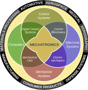
Figure 1.1 Mechatronics Euler diagram (Alciatore, Histand et al. 2007) ... 1
Figure 1.2 Main stages of product design process ... 2
Figure 1.3 SysML as a common modeling language and mapping between different domains (Shah, Kerzhner et al. 2010) ... 6
Figure 1.4 Functional Modeling (Stone, Wood et al. 2000) ... 8
Figure 1.5 Function behavior state (FBS) (Umeda, Tomiyama et al. 1995) ... 8
Figure 1.6 Graphical representation of a dependency ... 10
Figure 1.7 Analysis and synthesis properties and dependencies (Qamar, Paredis et al. 2012) ... 11
Figure 1.8 Task DSM (Braha 2002) ... 13
Figure 1.9 Example of a Multiple Domain Matrix (MDM) (http://www.plattformstrategie.de/) .. 15
Figure 2.1 Material, Energy, and Signal flow stereotypes ... 21
Figure 2.2 Function stereotype ... 21
Figure 2.3 Custom functional modeling diagram ... 21
Figure 2.4 Material flow hierarchical decomposition in SysML ... 22
Figure 2.5 Function hierarchical decomposition in SysML ... 22
Figure 2.6 Custom functional modeling diagram example ... 22
Figure 2.7 Functional modeling diagram representation in CLIPS ... 25
Figure 2.8 Exported functional diagram using CLIPS templates sample ... 26
Figure 2.9 Dominant flow module (Stone, Wood et al. 2000) ... 27
Figure 2.10 Branching flow module (Stone, Wood et al. 2000) ... 27
Figure 2.11 Conversion-transmission flow module (Stone, Wood et al. 2000) ... 28
Figure 2.12 Flow template with chain slot CLIPS ... 29
Figure 2.14 Rule that identifies flows that branch CLIPS ... 30
Figure 2.15 Meta-dependency modeling ... 31
Figure 2.16 Meta-dependency elements ... 31
Figure 2.17 Affecter and affected meta-dependency tagging slots ... 32
Figure 2.18 Adverse effect dependency stereotype bloc ... 33
Figure 2.19 createDependency CLIPS rule ... 34
Figure 2.20 Design procedure flowchart ... 35
Figure 3.1 temperature regulator functional model ... 37
Figure 3.2 Electric field DSM and heat DSM of temperature regulator ... 38
Figure 3.3 Partial Quadrotor drone functional model ... 40
Figure 3.4 Chains of functions resulting from CLIPS ... 43
Figure 3.5 Chains of flows in SysML functional diagram ... 44
Figure 3.6 Preliminary modularization ... 45
Figure 3.7 Vibration DSM ... 46
Figure 3.8 Heat DSM ... 46
Figure 3.9 Electric field DSM ... 47
Figure 3.10 Power supply and Power Control modules ... 50
CHAPTER 1
INTRODUCTION AND LITERATURE REVIEW
1.1 Introduction to mechatronics
Mechatronics is a multidisciplinary design process that covers a very wide spectrum of products and industries ranging from fully automated manufacturing lines, biomedical devices, agricultural equipment, aerospace, automotive, military defense systems, to various other consumer products. Mechatronics relies on the synergic integration of mechanical, electrical, control and software engineering to deliver simple products that outperform other products in terms of efficiency, precision, cost and reliability. It not only improves the design of products, it also allows to create new functions that were not possible before, such as active suspension and electronic stability in the automotive industry and fly-by-wire in aeronautics (Jürgen Gausemeier & Moehringer, 2003).
Figure 1.1 Mechatronics Euler diagram (Alciatore, Histand, & Alciatore, 2007)
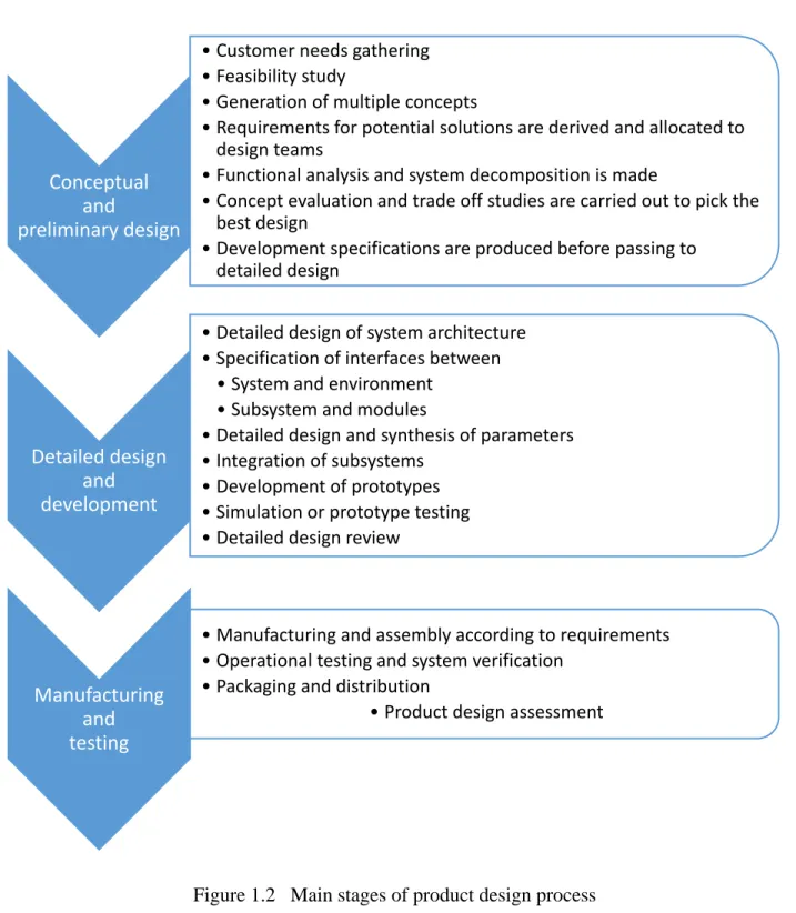
Figure 1.2. Illustrates general idea of how the design process of a mechatronic product is usually carried out. The nomenclature and subsections can vary depending on the design methodology and the industry in question. The process is divided in two main categories in terms of conceptual
and preliminary design followed by manufacturing and testing. In this master thesis we do not consider the market aspect of the mechatronic products.
Figure 1.2 Main stages of product design process
Conceptual and
preliminary design
• Customer needs gathering • Feasibility study
• Generation of multiple concepts
• Requirements for potential solutions are derived and allocated to design teams
• Functional analysis and system decomposition is made
• Concept evaluation and trade off studies are carried out to pick the best design
• Development specifications are produced before passing to detailed design
Detailed design and development
• Detailed design of system architecture • Specification of interfaces between
• System and environment • Subsystem and modules
• Detailed design and synthesis of parameters • Integration of subsystems
• Development of prototypes • Simulation or prototype testing • Detailed design review
Manufacturing and testing
• Manufacturing and assembly according to requirements • Operational testing and system verification
• Packaging and distribution
Creating development solutions for the design of mechatronic products is not an easy task. In order to contribute to this field of research, it is important to identify and understand the challenges faced in both academia and in the industry throughout the different stages of the design process (Mohebbi, Achiche, Baron, & Birglen, 2014).
1.2 Summary of mechatronic design challenges
The multi-disciplinary nature of mechatronics makes the design process a complex activity where designers from various backgrounds and work proficiencies have to cooperate closely to deliver a functional and optimal product. Unfortunately, designers rarely have sufficient knowledge outside their domain of expertise (Tomiyama, D’Amelio, Urbanic, & ElMaraghy, 2007) and are usually not well trained to integrate their work with other disciplines. During creative meetings they have difficulty sharing models and information, and often hesitate to communicate with one another (Salminen & Verho, 1989) due to a lack of a common language among disciplines to represent concepts (Albers et al., 2011). When looking at the system from a domain specific point of view they interpret realities differently, make various assumptions about the product, and end up forming their own mental model of the system (Danilovic & Browning, 2007). With this mindset, it is difficult to understand the overall design, its goals and purposes, and it makes the design process inefficient. Driven by professional loyalty, designers try to come up with solutions or optimize the subsystems they are working on in ways they think are beneficial to the overall system. However, a good mechatronic design is not always a combination of optimal subsystems but a harmonious interaction of its subsystems. For example, a mechanical engineer might optimize the drive train of a machine to minimize backlash, when this problem can be solved by a control engineer using programmatic compensation. While both alternatives lead to the same result, the mechanical solution increases design and manufacturing costs.
To succeed in an ever evolving market, a fast paced design process with a high degree of innovation is required. During product development designers have to cope with modified customer requirements, changes in regulations, advances in technology, etc. all while trying to reduce the project lead time. Some of the major challenges faced during a design process of this kind are synchronizing the design activities (Jurgen Gausemeier, Frank, Donoth, & Kahl, 2009)
and managing the dependencies that arise as a consequence of the interactions between the different disciplines (J. M. Torry-Smith, Mortensen, & Achiche, 2014). Designers also face difficulty in evaluating design concepts and assessing the consequences of selecting between alternatives (Mohebbi et al., 2014; J. M. r. Torry-Smith et al., 2011).
1.2.1 Mechatronic design methods
A lot of research effort has been put recently in developing a reliable design methodology for mechatronic systems, however, these endeavors have not completely reached their goal yet (Blessing & Chakrabarti, 2009). A Traditional design method, or a sequential method, exhibits a successive flow of activities where design tasks are separated in a manner that some parts use information resulted by the design of previous parts (e.g. control engineers use physical parameters provided by mechanical engineers to design a stabilization system) (Mohebbi et al., 2014). In a concurrent design method, all phases of a product’s lifecycle are taken into consideration during conceptual design and products are usually divided into single domain subsystems that are designed simultaneously. To ensure consistency during assembly, special attention is needed when designing the interfaces among the subsystems. Preferably, it is important to focus on the interaction between the different engineering disciplines rather than only on the subsystem interfaces (Wikander, Törngren, & Hanson, 2001). Sequential design does not meet the requirements of today’s fast paced multidisciplinary product development. It lacks the flexibility to deal with dynamic markets and is unsuitable for complex system integration, which leads to increases in design cost and development time (Wang, Shen, Xie, Neelamkavil, & Pardasani, 2002). Concurrent design is a means to reduce the project lead time and benefit from the multidisciplinary design synergy (J. M. Torry-Smith et al., 2014). It allows designers, early in the design process, to detect and deal with issues related to later stages of the design (Rzevski, 2003) which can also be used to manage the interactions between designers and their designs (Mohebbi et al., 2014). Even though a concurrent design approach has desirable advantages, it has been reported in the industry that traditional and sequential design methods are still being used (Behbahani & De Silva, 2007) because there is still no formal and systematic approach that promotes it. And that is due to the complexity of multidisciplinary systems, the difficulty in
synchronizing the development activities, and the lack of methods and tools to manage dependencies that arise between subsystems and disciplines during design.
1.2.2 Tools, Support, and Integrated solutions for mechatronic design
To assist engineering designers during the development activity of mechatronics many solutions have been proposed, and many have been implemented and are used in the industry. These solutions range from design guidelines and frameworks to paper based tools and software (J. M. Torry-Smith, Mortensen, Ploug, & Achiche, 2015). Advancements in computer and software technologies to date have extremely facilitated engineering design. Providing computational support early in the design process has a lot of benefits view that most "added value" to a product is contributed during this phase (Starling & Shea, 2005). Contradictorily, most of the available tools, such as CAD drawing tools, thermal simulation tools, computational fluid dynamics tools, or control and instrumentation tools, only support later stages of design. When it comes to conceptual design, designers use a variety of tools for organization activities such as managing requirements, but there is still a lack of tools that support the design synthesis activity (Wölkl & Shea, 2009). Translating customer requirements into functional requirements and developing product architectures are important but difficult parts of conceptual design and there is ongoing research in this field to provide computational support (Albers et al., 2011; Helms & Shea, 2012; Komoto & Tomiyama, 2012).
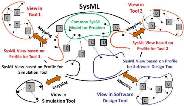
As previously mentioned, the design of mechatronics greatly benefits from concurrent and integrated design, where all phases of the design are considered starting from the beginning, and all the domains involved cooperate simultaneously to the design activity. The same applies to the software tools used to support design. Interoperable programs can exchange and share models and coupled or linked tools communicate at runtime. A lot of frameworks have been developed to automate model exchange between various tools. For example, SysML, a model based system engineering language, was used to represent a common design model of a system (Shah, Kerzhner, Schaefer, & Paredis, 2010). SysML is a powerful tool that allows designers to capture requirements and to model the structure and behavior of a system. As shown in Figure 1.3, to address issues associated with multi-view modeling, the common SysML model was used to map
models between domain specific tools and to represent the dependencies between them, thus supporting designers throughout the design process.
Figure 1.3 SysML as a common modeling language and mapping between different domains (Shah et al., 2010)
Integrated programs on the other hand allow the work in different domains and at various design phases within the same tool (Mohebbi et al., 2014). For example, a lot of mechanical CAD tools incorporate tools from other domains such as electronics and control modeling into their software. While design frameworks and integrated tools are desirable, even with the considerable research being conducted there are sill a number of challenges to be addressed before tools will allow efficient integration and use of multidisciplinary tools and data. Some of the major challenges are developing a single language that can effectively capture all the needed information in multi-disciplinary design, and ensuring consistency between the models of the various domain specific tools (Shah et al., 2010).
1.3 Functional modeling
Designers map ideas they conceive to a semantic domain they understand. They represent concepts by drawing sketches, graphs, and diagrams to facilitate sharing and explanation of thoughts between team members. Functional modeling allows modeling at an abstract level and can be used by designers of various expertise as a common language to communicate ideas during conceptual design. By breaking down the overall system into small easy to solve sub-functions, they can easily concretize requirement specifications into product concepts. (Eisenbart, Blessing, & Gericke, 2012).
The definition of function in the literature varies a lot depending on the field of study (Far & Elamy, 2005). When it comes to engineering design there are multiple definitions that can be put into two categories. Some definitions emphasize that for a function to be fulfilled a transformation has to take place, whereas others state that a goal or a requirement has to be achieved (Crilly, 2010), namely transformation functions and purpose functions.
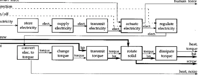
When modeling a product, different designers tend to generate distinct functional models. To help make the design task more consistent, and get repeatable and meaningful models from such a representation, a formal function representation is needed. A lot of efforts, such as NIST (Szykman, Racz, & Sriram, 1999) and TIPS (Altshuller, 1984), have been made to provide a functional vocabulary to model engineering systems. The functional basis for design reconciles and integrates these two efforts into a more evolved modeling language (Hirtz, Stone, McAdams, Szykman, & Wood, 2002). It consists of a standardized set of functions and flows where transformation functions are characterized by input/output relations in the form of verb-noun pairs (function-flow pairs). Functions can be connected by flows of material, energy, or signal to form a functional diagram that abstractly describes the product. Using a standardized set of functions and flows not only reduces ambiguity and ensures consistency; it forms a formal language that can be analyzed by algorithms and rules, thus it provides a strong foundation for computational support.
Figure 1.4 Functional Modeling (Stone, Wood, & Crawford, 2000)
Another research effort, the function-behavior-state (FBS) (Umeda, Tomiyama, & Yoshikawa, 1995), a modeling scheme of function for conceptual design, states that transformation functions do not provide enough flexibility for designers to model without reference to behavior and structure. Purpose functions are used instead, and are defined as human intentions. These functions are then associated with behaviors which are a more objective representation of the design based on physical principles.
Functional modeling also acts indirectly as a design scheme that guides design activities such as decomposing problems, generating concepts, and creating product architectures (Hirtz et al., 2002). To allow modular design to be carried on earlier in the product development, heuristics were developed to search for and identify chains of functions in a functional diagram (Stone et al., 2000). A chain of functions is a group of functions that are aggregated based on the type of transformations that occur to the flows that go through them. Chains, also called modules, can either be replaced by existing components that fulfill their task or labeled as parts of the product that need to be designed. This helps dividing the design activity and assigning tasks to teams starting from conceptual design.
Functional modeling acts as a bridge between human intentions and the physical structure and behavior of a product (Umeda et al., 1995). When used in conjunctions with artificial intelligence techniques, smart modeling tools can be created to assist designers in product development related activities. The research field that relates these two fields is called functional reasoning (Chandrasekaran, 1994). There are three aspects to a functional reasoning framework, an ontology, a representation scheme, and a reasoning method (Far & Elamy, 2005). Ontology is defined as “a formal, explicit specification of shared conceptualization.” (Studer, Benjamins, & Fensel, 1998). For example, the functional basis for design (Hirtz et al., 2002), previously presented, is an ontology that describes the function modeling domain and the entities in it. The representation scheme models the entities of the ontology and the relations between them, such as their hierarchical decomposition. The reasoning method infers and explains how the entities function. A functional reasoning system can be used for planning, conceptualization, or explanation purposes, by applying various artificial intelligence techniques such as heuristic search, exploration and exploitation, pattern matching, and clustering (Erden et al., 2008).
A substantial amount of work has been put in this field of research. For example, an automated modularization scheme was developed by using functional reasoning (Van Beek, Erden, & Tomiyama, 2010). The function behavior state was used to model the system and derive relationships between functions, an adapted k-means clustering algorithm was then used to group related functions together to better assign design activities and visualize dependencies in the system.
Another example that applies exploration and exploitation, automates the synthesis of product architectures (Helms & Shea, 2012). A function behavior structure is used to model a system and
then, using object oriented graph grammars, various combinations components that can achieve the desired functionality are generated.
1.4 Dependencies in mechatronics (multi-domain) systems
1.4.1 Dependency definition, characteristics, and classification
In business, a dependency is defined as “Relationship between conditions, events, or tasks such that one cannot begin or be-completed until one or more other conditions, events, or tasks have occurred, begun, or completed.” (BusinessDictionary.com). When it comes to multidisciplinary engineering design there is no clear definition of dependency. In most relevant research, the definition is taken for granted and it is often hard to distinguish between dependency and the particular domain of interest. There have been very few attempts to formalize and describe the distinctive natures of dependencies, most of those attempts are applied in computer science. A generalized definition of dependency is a relationship between two entities, where a change of state in one entity leads to a change of state in the other entity (Cox, Delugach, & Skipper, 2001). As shown in Figure 1.6, in a dependency d (A, B) between two entities A and B, where A depends on B, the entity A is referred to as the dependent and the entity B is referred to as the antecedent.
Figure 1.6 Graphical representation of a dependency
Dependencies were assigned the following 6 attributes to facilitate their classification and grouping (Keller, Blumenthal, & Kar, 2000). Domain, strength, type, activity, formalization, and criticality. Each attribute can take different discrete values, and dependencies that have similar attributes can be grouped together. Strength for example, expresses how strongly the dependent depends on the antecedent, it can take the 3 following values, mandatory, optional, and none.
A different approach (Qamar, Paredis, Wikander, & During, 2012) proposes taking into account the synthesis and analysis nature of properties and dependencies. Synthesis properties (SPs) are used to define system alternatives whereas analysis properties (APs) are used to constitute predictions rather than specifications of the system alternatives. For example, a designer defines the geometry of a part which is a synthesis property and predicts its cost or weight which are analysis properties. A dependency here is defined as a relationship between two properties, where the value of a property depends mathematically on the value of another property. A synthesis dependency reflects choices made by a designers and always results in a synthesis property. For example, a synthesis property can be heuristics for choosing controller gains. Analysis dependencies on the other hand, are relationships between a set of analysis and synthesis properties and are used to derive new analytical properties. An example of an analysis dependency is the prediction of the settling time of a system due to chosen controller gains and other properties such as the mass.
Figure 1.7 Analysis and synthesis properties and dependencies (Qamar et al., 2012)
The most recent state of the art on dependencies in multi-domain systems is a proposal that classifies product related dependencies during design of mechatronics (J. M. Torry-Smith et al., 2014). By studying and investigating three mechatronic projects, 13 types of dependencies were identified. These dependencies can occur between the following attributes of a product: Functions, means, and properties. For example, a type of dependency between two functions, can be a “sync function” and is defined as a dynamic relation between functions where the timing of the initiation or ending of the concurrently executed functions. Another type of dependency
between a function and a means is an adverse effect, an undesired effect generated by a component and affects another component. For example, electromagnetic waves generated by a motor affect the function of an LCD screen. More information on the following types of dependencies can be found in (J. M. Torry-Smith et al., 2014): Causal function, state/time function, response function, Fu-M disposition, cumulative Fu-M, property scheme, multidisciplinary means, volume allocation physical, liveliness, physical interface, communication interface.
1.4.2 Common dependency management tools
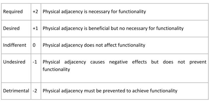
Matrix based complexity management tools are the most common way of handling dependencies. Since its introduction in the early 80ies, the Design Structure Matrix (DSM) has been widely taken up in research (Kortler & Lindemann, 2011). The DSM, also referred to as dependency structure matrix, is a square matrix that provides a compact visual representation of dependencies. Elements in a DSM belong to the same domain (components, requirements, tasks…) and are identical on both axes. Dependencies are filled in the matrix cells and should be of the same type, semantically and quantitatively. For example, in Figure 1.8, binary entries in the DSM show tasks that satisfy the same requirements (Braha, 2002), by visually aggregating related tasks and optimally assigning them to working teams the cost and length of product development can be kept at a minimum. In another application, a DSM was used to visualize spatial dependencies between components by mapping them in terms of physical adjacency (Pimmler & Eppinger, 1994). To better express these dependencies, entries in the DSM are numerical instead of binary and range from -2 to 2 as shown in Table 1.1.
Figure 1.8 Task DSM (Braha, 2002)
Table 1.1 Spatial adjacency (Pimmler & Eppinger, 1994)
Required +2 Physical adjacency is necessary for functionality
Desired +1 Physical adjacency is beneficial but no necessary for functionality
Indifferent 0 Physical adjacency does not affect functionality
Undesired -1 Physical adjacency causes negative effects but does not prevent functionality
Detrimental -2 Physical adjacency must be prevented to achieve functionality
DSMs were extended to Domain Mapping Matrices (DMMs) to include elements from two different domains. DMMs are usually rectangular, and elements from each of the domains are respectively placed either along the vertical axis and the horizontal axis or vice versa. In the work presented by (Danilovic & Browning, 2007), an aircraft design was undergoing a large number of technical upgrades which were based on multiple business deals with various clients; the project
was also divided into functional elements for final system approval and certification (landing gear and breaking system, secondary power system…). Here, a DSM was used to visualize and group related business deals into sub-projects and assign them to different teams. However, with configuration, many designers had to work separately on different business deals that are highly interdependent on the functional level. These dependencies and their degree of interaction (the extent to which the antecedent affects the dependent) were identified and entered in DMM that maps business deals against the elements of the functional organization. By rearranging columns in the DMM, dependencies were clustered to identify sub-projects (group of business deals) that require a high level of coordination and integration.
Managing dependencies in mechatronic systems is a complex procedure that requires modeling multiple domains while viewing various dependency types. These requirements can be met by the Multiple Domain Matrix (MDM), a square matrix that has system elements in exact order on both axes. It is comparable to a DSM except that it can include elements of different types that are grouped into domains on each axis. As shown in Figure 1.9, the resulting MDM is formed out of smaller matrices with DSMs on the diagonal and DMMs elsewhere. Different types of dependencies can be used individually in each sub matrix, therefore MDMs can include all possible combinations of domains and dependency types that can be viewed individually in its DSMs and DMMs. This makes it easier for designers to understand the relationships between elements and apply various analysis methods, such as clustering, separately on each one of the sub-matrices.
Figure 1.9 Example of a Multiple Domain Matrix (MDM) (http://www.plattformstrategie.de/)
One of many applications where MDMs are used, is the analysis of multiple architectures of a BMW hybrid electric vehicle (Gorbea, Spielmannleitner, Lindemann, & Fricke, 2008). Data were collected through meetings with engineering domain experts and dependencies between and amongst the functional and component domain were used to build the MDM model. ΔMDMS and ΣMDMs, respectively MDM matrix subtraction and matrix addition, where used to compare and highlight the differences between individual architectures of the hybrid electric vehicle. Given that entries in the MDMs are either 0 or 1, a ΔMDM results in a matrix that has 0s where no differences are present and 1s/-1s where dependencies are present in only the first/second MDM. ΣMDM on the other hand provides another kind of information, for example, by looking at the component/function DMM in the ΣMDM of all MDMs (sum of all matrices) one can see the different components that can fulfill a function. This kind of information is very valuable for automation of design, it can be used to compile a repository of components with information on which functions they can fulfil and to which degree (how often).
One of the difficulties that limit the use of matrix based complexity management tools is he complexity and the cost in time of information acquisition. In the previously presented examples, most of the work done using DSMs was applied to designs of existing products, and the
researchers relied on meetings with experts to get information on dependencies between elements in the matrices. When developing new products there is usually a lack of existing documentation, acquiring information to use in DSMs requires time consuming interviews (Lindemann, Maurer, & Braun, 2008). Another difficulty is the manual filling of dependencies in matrices, this activity is also time consuming and highly error prone. These issues are addressed in (Van Beek et al., 2010) and overcame by automatically extracting information on dependencies from the function-behavior-state model and filling them in the matrices. There is also ongoing research to develop clustering algorithms and methods (Hölttä-Otto, Tang, & Otto, 2008; Zakarian, 2008) for complexity management tools, because to get meaningful information from DSMs and understand it, designers rely heavily on rearranging and grouping dependencies in the matrices.
CHAPTER 2
RESEARCH FRAMEWORK
2.1 Challenges addressed and Objective
The main challenges in multi-disciplinary design have been identified in the literature review, the research carried out in this master thesis addresses difficulties faced during preliminary phases of design. By studying other academic efforts, it was revealed that there is a strong need for a design framework for preliminary design complemented by a computational support tool that integrates the conceptual model of mechatronic products with software used at later stages of design, such as CAD and other domain specific tools. As previously mentioned, nowadays’ markets are constantly evolving, new competitive products are rolled out, new regulations are put in place, new technologies are developed, and so on. To meet the changes in requirements without much increasing the project lead time, the design framework and support tool should be flexible enough to allow changes to the design with minimum efforts from designers. The major difficulties that arise when modifying a design are the ability to determine the consequences that result because of those changes, assessing the effects of choosing between alternatives, and evaluating the design concept.
Dealing with these difficulties requires strong communication between the various disciplines and management of dependencies. Advancements in matrix based dependency management tools have come a long way, their limitations do not lie in the tools themselves but in the difficulty acquiring information about dependencies and modeling them. In the preliminary phases of design, the product concept is not very well defined yet and most of the underlying dependencies are only known at a coarse grain level in the designers' mind (Qamar et al., 2012). As the number of component in a system increases, the number of dependencies increases exponentially. Modeling them often proves to be quite time consuming, and shifts the designers’ attention away from solution finding. Often these dependencies are left unattended, only to reappear at later stages of design and cause integration problems which require costly design iterations to fix. The work in this research proposes a design methodology using a functional reasoning framework and a new way to model dependencies during conceptual design. The aim is to provide a dynamic modeling tool that allows designers to focus on solution finding, and a
methodical acquisition and representation scheme of dependencies that encourages designers not to ignore pertinent information and boosts the synthesis activity.
This master thesis is framed by the following research questions: Can a functional reasoning framework act as a common language understood among designers and improve collaboration? Of this research question stems the following sub-questions: Can the project lead time be reduced by capturing and managing abstract dependencies during conceptual design? Will it help designers better integrate work from various domains to avoid design iterations?
2.2 Proposed framework and dependency modeling
2.2.1 Functional Reasoning Framework
In this section, we will introduce the functional reasoning framework that was used in order to describe the product flow and help highlight the dependencies.
2.2.1.1 Ontology
The term ontology has its roots in philosophy where it is defined as a systematic account of existence. In engineering, ontology is an explicit specification of conceptualisation (Gruber, 1993). It is a set of objects and relationships among them that are used to represent knowledge in a domain, this set forms a primitive vocabulary for knowledge based systems (Kitamura, Ikeda, & Mizoguchi, 1997) such as the reasoning method presented in the next sections. Flexibility and formality are two qualities of ontology that often have a negative correlation. For example, representing functions as a finite number of types lacks flexibility and does not allow designers to cover all possible functionalities (Erden et al., 2008). However, such a representation provides a formal vocabulary that can be easily computationally searched and analyzed.
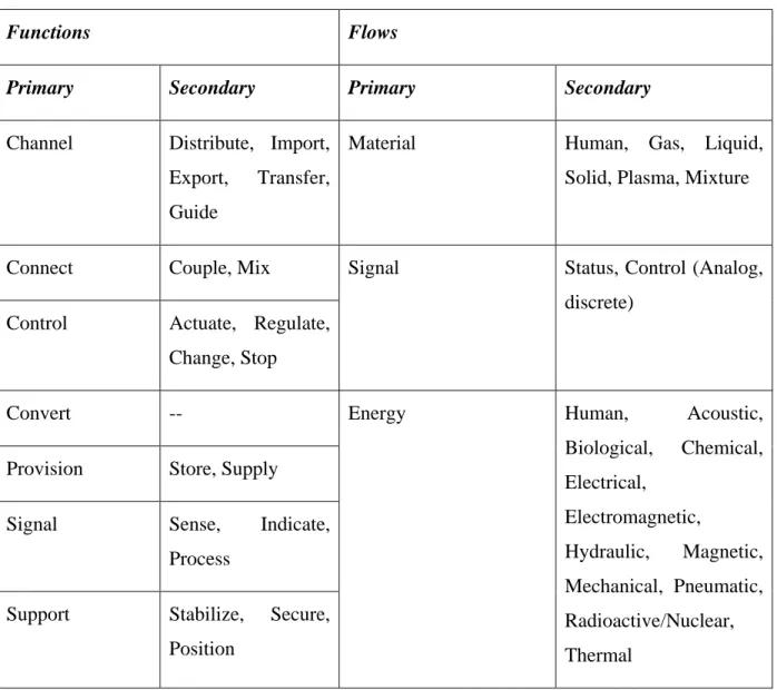
The functional basis for design presented in the literature review will be used as an ontology in this functional framework, it is a comprehensive list of function-flow that can be used to model multi-domain systems. The set of functions and flows are shown in Table 2.1. Such a formal representation allows repeatable and meaningful results from modeling and is meant for use in
design repositories, product architecture, and design synthesis (Hirtz et al., 2002). The functional basis for design has its limitations and advantages, the aim here is to develop a functional reasoning framework that serves as a proof of concept and a structure for the dependency modeling method proposed in the next sections.
Table 2.1 Functional basis set of functions and flows (Hirtz et al., 2002)
Functions Flows
Primary Secondary Primary Secondary
Channel Distribute, Import, Export, Transfer, Guide
Material Human, Gas, Liquid,
Solid, Plasma, Mixture
Connect Couple, Mix Signal Status, Control (Analog,
discrete) Control Actuate, Regulate,
Change, Stop
Convert -- Energy Human, Acoustic,
Biological, Chemical, Electrical, Electromagnetic, Hydraulic, Magnetic, Mechanical, Pneumatic, Radioactive/Nuclear, Thermal
Provision Store, Supply
Signal Sense, Indicate,
Process
Support Stabilize, Secure, Position
2.2.1.2 Developing a Representation Scheme
The scope of this research is to support designers with concept generation and dependency management, however the farfetched ultimate goal is to provide a tool that allows concurrent and integrated design throughout the design process. SysML, defined in italic below, is a very
powerful language that can, with modifications, fulfill this task and act as a representation scheme for the functional basis for design. Also, SysML has already been used as a common modeling language to map between various domain specific tools as shown in Figure 1.3 (Shah et al., 2010).
“SysML is a general-purpose graphical modeling language that supports the analysis, specification, design, verification, and validation of complex systems. These systems may include hardware and equipment, software, data, personnel, procedures, facilities, and other elements of human made and natural systems. The language is intended to help specify and architect systems and to specify components that can then be designed using other domain-specific languages, such as UML for software design, VHDL for electrical design, and three-dimensional geometric modeling for mechanical design. SysML is intended to facilitate the application of an MBSE approach to create a cohesive and consistent model of the system.” (Friedenthal, Moore, & Steiner, 2014).
SysML is decomposed into meta-classes that are used to illustrate concepts in the modeling domain. It uses stereotypes to support domain specific modeling, they are mechanisms that allow customization of the meta-classes to suit the designers’ needs. To speed up modeling, SysML also supports the creation of model libraries, collections of reusable elements that can be defined by a system modeller.
There are multiple tools in the market that support the modeling language SysML. MagicDraw, the multi award-winning UML business process, architecture, software and system modeling tool with teamwork support, is used here due to the availability of an OpenAPI that facilitates integrating a reasoning method to the functional framework.
To create a representation scheme and provide a computational tool to use for functional modeling, the customization capabilities of SysML were used in this master thesis to create a custom functional modeling diagram and a model library of the set of functions and flows presented in the functional basis for design.
The material, energy, and signal flow stereotypes shown in Figure 2.1 extend the activity parameter node, object flow, and class meta-classes, while the function stereotype in Figure 2.2 extends the meta-class call behavior action. This represents one of the original contributions of the work presented in this master thesis and will be further explained in the following sections.
Figure 2.1 Material, Energy, and Signal flow stereotypes
Figure 2.2 Function stereotype
The meta-classes activity parameter node, object flow, and call behavior action in SysML are used in activity diagrams. Extending these stereotypes allows the creation of a custom functional modeling diagram and a user interface in MagicDraw as show in Figure 2.3.
Figure 2.3 Custom functional modeling diagram
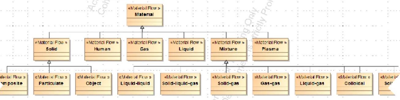
Figure 2.4 and Figure 2.5 show the functional basis for design libraries. A hierarchical decomposition was achieved using the generalization path symbol which indicates for example that a particulate flow is a solid flow, which is also a material flow. The hierarchy allows flexible modeling, where a more specific flow can be connected to a more abstract port. For example, a gas-liquid flow can be connected to a to mixture port, but not vice versa. It also allows
writing algorithms and rules at different levels of abstraction which will be elaborated in the next section.
Figure 2.4 Material flow hierarchical decomposition in SysML
Figure 2.5 Function hierarchical decomposition in SysML
Figure 2.6 shows a part of the functional diagram found in Figure 1.4 modeled in MagicDraw using the custom functional diagram and the functional basis libraries.
Figure 2.6 Custom functional modeling diagram example 2.2.1.3 Implementing a Reasoning method
This section is divided into three parts. The first two parts explain how the MagicDraw openAPI and the rule based expert system “CLIPS” were used to develop and implement the reasoning method, and how they can infer information from the functional modeling diagram to support the
engineering designers in planning and conceptualization. The third part illustrates an example where possible heuristics followed by designers were integrated into the reasoning method to automatically modularize the functional model.
2.2.1.3.1 Linking the system modeling and the reasoning method: MagicDraw openAPI plug-in The openAPI supports the modification of Magic Draw’s functionality through the creation of plug-ins. After customizing SysML to support functional modeling using the functional basis for design, a plug-in was developed using JAVA to check the functional diagrams for consistency at the representation level and report it back to the designer. For example, the plug-in would check for things like: ports that are not connected to a flow, types of flows that do not match, a “branch” function that does not split the incoming flow into 2 outgoing flows, ... If the functional diagram is proved to be complete/consistent, the plug-in was coded to proceed and extract relevant information from the functional diagram and export it in a more simplified format that will be used by the rule based expert system (CLIPS) and explained in the next section.
This automated approach reduces the burden on the engineers as it helps them carryout a very high-level of consistency check-up in their models in a very effective, systematic, and automated manner. It is worth noting that from now on, in this master thesis, the MagicDraw openAPI plug-in will be referred to as MagicDraw plug-plug-in.
2.2.1.3.2 Rule-based expert system CLIPS
Expert systems are computer programs where the knowledge and the reasoning process of human experts are codified in an attempt to mimic their decision making skills. Rule-based expert systems are usually composed of these main components: an interaction mechanism, a knowledge base, and an inference engine. Rule-based expert systems are used in various engineering domains (Achiche, Appio, McAloone, & Di Minin, 2012; Achiche, Baron, Balazinski, & Benaoudia, 2007; Ren, Balazinski, Jemielniak, Baron, & Achiche, 2013)
The interaction mechanism can be either a user interface that the expert system uses to interact with a user or an integration platform that allows it to interact with other computer applications.
The knowledge base contains a set of rules that are coded to encapsulate information acquired from human experts. Rules are written in an If A Then B format, where A is called the antecedent and B is called the consequent. When the antecedent of a rule is matched to data in the working memory, data usually provided by the interaction mechanism, the rule is said to be satisfied and can be triggered to perform the action stored in its consequent. Actions could be anything from modifying data in the working memory, storing new information for other rules to use, to reporting back to the interaction mechanism.
The inference engine is the main processing unit of an expert system, it manages the rules that are satisfied and choses in which order to trigger them based on priorities set in the code and the followed search strategy.
CLIPS, an acronym for C Language Integrated Production System, is an expert system tool developed by NASA and released in 1986, and will be used for reasoning in the functional framework. As previously mentioned, the MagicDraw plug-in was used to extract relevant information from the functional diagram and export it to the working memory of CLIPS. The functional modeling diagram in CLIPS is represented using the templates shown in Figure 2.7 and developed in this research work. Input and output templates define the elements that are on the boundary of the functional diagram.
All elements in a SysML diagram have an unique identifier. To have an exchangeable model between MagicDraw and CLIPS, the slot “id” was added to all templates of the CLIPS representation and is used to store the unique identifier.
The slot “name” is not needed for computational purposes and is there only to facilitate debugging and explanation.
The slot “type” is used to indicate the category of the function or flow found in the functional basis for design set.
Figure 2.7 Functional modeling diagram representation in CLIPS
The slots “source-id” and “destination-id” store the unique identifiers of the functions to which a flow is connected. Figure 2.8 shows a sample of how the functional diagram template representation is written when exported by the plug-in to CLIPS.
Since the ontology and the representation scheme are hierarchically structured, rules can be written to reason at various levels of abstraction. Rules can be used for various goals such as pattern matching and component selection, heuristic search, clustering … The next section illustrates the implementation of heuristic search on the functional diagram in CLIPS to identify modules of functions. An example of a rule is shown inFigure 2.14.
Figure 2.8 Exported functional diagram using CLIPS templates sample
2.2.1.3.3 Assisted modularization using rule-based heuristics
As previously mentioned in the literature review, functional modeling acts indirectly as a design scheme that guides designers in activities such as decomposing problems, generating concepts and creating product architectures (Hirtz et al., 2002). To allow modular design to be carried on earlier in the product development phase, three heuristic methods for identifying modules in a functional diagram were developed. The efficacy of these methods was confirmed and verified by applying them on a database of 70 consumer products (Stone et al., 2000).
In the work presented here, we aim to support engineering designers in modularising functional models. Before explaining how these heuristics are translated, in this work, to be used as embedded rules in CLIPS, they are presented below, each with a corresponding figure that illustrates it.
The Dominant flow heuristic, as shown in Figure 2.9, defines a module as a set of sub-functions which a flow passes through, from entry or initiation of the flow in the system to exit from the system or conversion of the flow within the system.
Figure 2.9 Dominant flow module (Stone et al., 2000)
The Branching flow heuristic, as shown in Figure 2.10, defines modules as the limbs of a parallel function chain. Each of the modules interface with the remainder of the product through the flow at the branch point.
The Conversion-transmission flow heuristic, as shown in Figure 2.11, defines a module as a conversion sub-function or a conversion—transmission pair or proper chain of sub-functions.
Figure 2.11 Conversion-transmission flow module (Stone et al., 2000)
Creating chains of functions by coding the heuristics at a high level of abstraction is very difficult if not impossible. Getting more information from the designing user about the functional diagram, such as to which flow each of the functions are applied, hinders the dynamic modeling capacity of the modeling tool, one of the main goals of this research master thesis.
Instead of identifying chains of functions, rules that identify chains of flows are coded. The results are then presented to assist the designing user modularize the functional diagram. If the diagram has a simple layout, the chains of flows will always correspond to the expected chains of functions. When the diagram is more complex, such as having multiple flows passing through functions, the user can be given the choice to select the resulting chains of flows that are pertinent. All the flows in a chain that is selected are marked as “primary flows” and the functions that they pass through are grouped to create a module. This method facilitates information acquisition about primary flows in the diagram and assists the designer in identifying modules faster.
The following logic was coded into CLIPS and is centered around the functional modeling representation defined in the templates above. To note, due to time limitation, but not technical, only the flow chain identification was coded and tested, but not integrated into MagicDraw. First, a new slot “chain” was added to the flow template, and a new “chain” template was created as shown in Figure 2.12 and Figure 2.13. The slot “chain” is an integer, its default value is 0, and it is used as a flag that indicates if a flow was added to a chain or not. The template chain, has a multi-slot “flow-ids” where the unique identifiers of the flows that belong to it can be added.
Figure 2.12 Flow template with chain slot CLIPS
Figure 2.13 Chain template CLIPS
As previously mentioned, the inference engine in an expert system decides in which order satisfied rules can be executed. CLIPS allows giving priority to some satisfied rules to be executed before other using “salience”. Salience can be added to the definition of a rule and can take values up to 99, rules with higher salience have higher priority.
To identify chains of flows, two types of rules are coded, ones that identify a starting point of a chain (a starting flow) and ones that propagate from the starting points adding flows to each chain until it they can no longer be satisfied. Rules that identify starting points have a higher priority to be triggered and identify these types of flows: input flows, flows that branch, flows that merge. Figure 2.14 shows an example of a rule that labels a branch of a flow as a starting point of a new chain. Section 4 shows an example where assisted modularization is used.
Figure 2.14 Rule that identifies flows that branch CLIPS
2.2.2 Dependency Modeling
This section proposes a methodical acquisition and representation scheme of dependencies that encourages designers not to ignore pertinent information and boosts the synthesis activity. During preliminary phases of design there is a lot of non-quantified abstract information that needs to be modeled, the following method aims to help experts concretize their knowledge on dependencies in multi-domain systems.
2.2.2.1 Modeling Using Meta-Dependencies Concept
Modeling dependencies using common graphical methods, such as shown in Figure 1.6, requires building relationships between each and every single element in the system. As the number of elements in a system increases, the number of dependencies increases exponentially, and
managing these dependencies becomes costly and time consuming if not impossible, specially when doing design modifications.
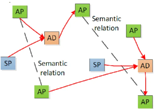
Instead of building relationships between all dependent elements, we propose the concept of meta-dependencies such as shown in Figure 2.15, where a dependency is defined as a relationship between an element (function, module, component, …) and a meta-dependency. Similarly to the graphical dependency shown in Figure 1.6, the elements E1 and E2 in Figure 2.16 are considered dependent and antecedent elements respectively and the potential relationship dependency between them is shown in dashed lines.
Early in the design process, dependencies tend to be too abstract to be easily represented and their existence is often uncertain. Since several elements share the same type of dependency, using a meta-dependency modeling scheme allows grouping these related dependencies under the same model. Therefore, this helps reduce the number of relationships to be created, and encourages implicit acquisition of abstract information during design activities.
Figure 2.15 Meta-dependency modeling
2.2.2.2 Tagging elements with adverse effect dependencies
To use a meta-dependency modeling scheme, the dependency at hand should be shared among several elements in the system. Adverse effects for example, are undesired effects such as heat, vibration, and electromagnetic waves, that are generated by one element and affect the functionality of other elements in the system. Adverse effects are one of many types of dependencies that can be modeled using the meta-dependency modeling scheme and will be used as an illustration in the rest of this research.
To reduce the graphical clutter and make the design process more dynamic, instead of building relationships with a meta-dependency we propose to tag elements with adverse effects. Using SysML’s customization mechanism two new property slots were added to the function stereotype, affecter and affected as shown in Figure 2.17. These slots can take as values adverse effects that are defined by the designer. When the slot affecter is tagged by an adverse effect, it implies that the function can generate such an undesired effect and that it has an antecedent relationship with this meta-dependency. When the slot affected is tagged, it implies that this function’s performance can be hindered by this adverse effect and that it has a dependent relationship with it.
Figure 2.17 Affecter and affected meta-dependency tagging slots
2.2.2.3 Automated Generation of the Dependency Matrix
As cited above, dependency structure matrices (DSMs) offer designers an overview of the system at hand and the relationships between its elements but are quite complex and time consuming to generate manually by engineers. By using the meta-dependency modeling scheme, DSMs can be automatically generated, thus freeing designers from filling them which saves them time and reduces possible human induced errors.
To achieve this, SysML’s customization mechanism, the functional reasoning expert system, and the MagicDraw plug-in were used in this master thesis.
As shown in Figure 2.18, the dependency relationship in SysML was extended to create adverse effects using a stereotype.
Figure 2.18 Adverse effect dependency stereotype bloc
Two multi-slots for the attributes Affecter and Affected were added to the function template in the CLIPS knowledge base. Then new rules were developed and then embedded to create an adverse effect dependency between functions that affect each other. An example of a rule is show in Figure 2.19 and explained in italic below, more complex rules can be written to derive dependencies by taking multiple factors into account and will be further discussed in the future work section.
If Function1 is affected by AdverseEffectA & Function2 is an affecter of AdverseEffectA
Then a Dependency of type AdverseEffectA will be created with dependent Function1 and antecedent Function2
Figure 2.19 createDependency CLIPS rule
The openAPI was then used to import the dependencies from the CLIPS generated file and create adverse effect dependencies between the two functions in the SysML model; and then create a DSM for each type of adverse effect to present them to the designer user. Section 4.1, Illustrating the principle, shows a design process example where multiple DSMs are created.
2.2.3 Design Procedure summary
Figure 2.20 sums up the design procedure and methodology that should be followed while using the developed design support tool in this master thesis. Engineering designers start the conceptualization of a mechatronic product by gathering customer needs and deriving requirements and then they proceed by translating these requirements into a functional model of the product. Here designers are required to simultaneously identify adverse effects that can possibly affect or be generated by the various functions and tag them appropriately.
To identify the product architecture, designers are required to use the assisted modularization to help them apply the heuristics and identify modules. They should also inspect the automatically generated dependency matrices to identify problematic functions or modules, identify important dependencies that should be expressed in more detail or be added to the evaluation criteria of the product.
While generating modular concepts, designers should take account of all the problematic dependencies. The easiest way to avoid some adverse effect dependencies is to choose compatible components in a system, however sometimes they can be avoided by creating new creative modules and changing the physical allocation of some components. If no solution can be easily implemented sometimes it is better to derive a new functional model of the product.
The following section will illustrate how this design method and the support tool can be used in two concrete examples.