HAL Id: hal-02064693
https://hal-univ-pau.archives-ouvertes.fr/hal-02064693
Submitted on 12 Mar 2019HAL is a multi-disciplinary open access archive for the deposit and dissemination of sci-entific research documents, whether they are pub-lished or not. The documents may come from teaching and research institutions in France or abroad, or from public or private research centers.
L’archive ouverte pluridisciplinaire HAL, est destinée au dépôt et à la diffusion de documents scientifiques de niveau recherche, publiés ou non, émanant des établissements d’enseignement et de recherche français ou étrangers, des laboratoires publics ou privés.
Influence of cement type on transport properties and
chemical degradation: application to nuclear waste
storage
C Perlot, J Verdier, M Carcassès
To cite this version:
C Perlot, J Verdier, M Carcassès. Influence of cement type on transport properties and chemical degradation: application to nuclear waste storage. Materials & Structures, 2005. �hal-02064693�
Influence of cement type on transport properties and chemical degradation: application to nuclear waste
storage
C. Perlot, J. Verdier and M. Carcassès LMDC, UPS - INSA Toulouse, France
Abstract:
The geological repository of nuclear waste in concrete containers is a possible storage method explored by ANDRA (Agence Nationale pour la gestion des Déchets RAdioactifs).
The concrete must display a high confinement capacity for long periods, characterized by transport properties and by the acido-basic buffer of hydrated cement. During service life, these properties can be endangered by chemical attack of underground water.
The cement type has an important influence on the concrete’s performances. Then, it is essential to establish appropriate mixtures and select accurate components. In this work an ordinary Portland cement and fly ash and blast furnace slag blended cement are compared.
To determine confinement capacities, transfer properties and mortars pore size distributions were investigated.
To predict the long term structure behavior, an ammonium nitrate test has been developed to enhance decalcification and to accelerate hydrolysis of cementitious materials.
Measurement of degraded depth with time regarding calcium content was carried out. Impact of decalcification on transport properties was evaluated.
Fly ash and blast furnace slag provide better properties for native mortars, and more principally diffusion properties, but not as much as necessary to limit leaching in degraded material by chemical attack.
Keywords: Fly ash, blast furnace slag, gas permeability, chloride diffusion, mercury intrusion porosimetry, ammonium nitrate degradation.
Résumé :
Le stockage de déchets radioactifs en formation géologique profonde est une voie d’investigation de l’ANDRA (Agence Nationale pour la gestion des Déchets RAdioactifs).
La barrière ouvragée cimentaire doit assurer une capacité de confinement pendant de longues périodes, caractérisée par ses propriétés de transfert et le maintien du tampon acido-basique du ciment hydraté.
Pendant la durée de service de l’ouvrage, ces propriétés sont modifiées par l’attaque acide des eaux souterraines. La nature du ciment influençant majoritairement les performances du béton, il apparaît essentiel de sélectionner les composants adéquats pour établir des formulations performantes.
Dans cette étude les performances en terme de durabilité d’un ciment Portland ordinaire et un ciment aux cendres volantes et aux laitiers sont comparées.
Les propriétés de transfert et la microstructure des mortiers sont mesurées pour en évaluer les capacités de confinement. Afin d’estimer le comportement à long terme de la structure, un essai de dégradation par le nitrate d’ammonium a été développé pour accélérer la décalcification des matériaux cimentaires. L’évolution de l’épaisseur dégradée au cours de l’attaque ramenée à la teneur en calcium est suivie. L’impact de la décalcification sur les propriétés de transfert est évalué.
Les cendres volantes et les laitiers semblent améliorer les propriétés des mortiers, notamment en terme de diffusion, mais pas assez pour résister à l’attaque chimique.
Mots clef: Cendres volantes, laitier, perméabilité au gaz, diffusion des chlorures, porosimétrie mercure, décalcification, nitrate d’ammonium.
1. Introduction
The storage in deep geological disposal of long-lived nuclear waste in concrete containers is a possible solution explored by the French national Radioactive waste management Agency (ANDRA).
Radioactive elements confinement is ensured by a series of barriers: waste containers, engineered barrier system and a geological media.
With regard to the performances required, concrete appears to be suitable to compose structure facilities and the Engineered Barrier System (EBS).
The confinement capacity is linked to two main properties of hydrated cement: firstly, high pH buffer (between 12.5 and 13.5) imposes physicochemical conditions propitious to radionuclides sorption; secondly the low permeability to gas and water and diffusion due to the dense microstructure limit penetration of external agents.
During the life time of the structure, the concrete is subjected to aggressive actions. Chemical conditions in host formation, low ionic concentration of underground water, impose high concentration gradient which leads to the diffusion of ions contained in the concrete interstitial solution to this aggressive solution and causes decalcification and dissolution of cement paste hydrates.
Chemical and physical deteriorations modify microstructure and thereby transfer properties and endanger radionuclides sorption by chemical stability and physical evolution that impair the sustainability of safe storage.
Due to its diffusive based mechanism, leaching presents a very slow kinetic. Usually this phenomenon is not taken into account for civil engineering facilities design but in a nuclear disposal it appears to be important given that the waste must be isolated for very long periods up to thousand of years.
Our studies focus on this decalcification scenario as a quality control criterion for design and operation of concrete structure in storage system.
The type of cement and its elementary composition govern the performances of concrete because of the different micro structural development during cement hydration. It is well known that transport properties through cementitious material are directly linked to its microstructure. ANDRA’s specifications for cement based material for such waste disposal had led to the selection of two cements. We have chosen to study the influence of the binder on transfer properties and on decalcification/hydrolysis.
2. Materials and samples
A previous ANDRA study selected suitable concrete components and mixtures for the waste disposal with regard to the specifications imposed by the interactions between EBS and host formation.
In the present work, experiments were carried out on mortars equivalent to the concretes. Considering that concrete chemical degradation is slower than mortar’s one, it leads to longer experimentation. The elementary representative volume for mortars, and so the dimensions of the samples, are function of the aggregates size. Furthermore, the degraded depth must be enough developed to measure transport properties in degraded zone. Then, it is easier to work with mortars.
We established mortars mixtures from the concretes selected by ANDRA. To be equivalent to the concretes, mortars have to be prepared from the same components. We used limestone sand 0/4 mm from Boulonnais (France) and a superplastizier, water reducer. The amount of sand to replace aggregates was calculated to maintain developed specific surface area of granules between concretes and mortars (1). Water was introduced to obtain free water-cement ratio equivalent to concretes one. But, as we have to consider engineering constraint, the concrete must keep enough fluid properties to be pumped during two hours. We used workability as a criterion to adjust the amount of water.
The first cement type used, referenced as CEM I, is an ordinary Portland cement (CEM I 52.5 R PM-ES) manufactured by Lafarge at Val d’Azergues (France). The second one is a blended cement containing 56% by mass of clinker, 22% by mass of fly ash and 22% by mass of blast furnace slag, named as CEM V/A 42.5 N PM-ES, which is commercialised by Calcia from Airvault (France). According respectively to European norms (NF P 15-317 and XP P 15-319) PM cements are recommended for marine environment works and ES cement are sulphate resistant.
The analysis elementary composition of the cements is summarised in tables 1 and 2. Fly ash are pozzolans in the sense that when suitable active, they react with water to give calcium silicate hydrates (CSH). Blast furnace slag is a hydraulic material reacting with water to product CSH. As chemical degradation is supposed to be controlled by leached calcium diffusion (2, 3) the main
interest in the comparison of this two mortars attack states in the fact that the initial quantity of calcium and the nature of the calcium hydrates are different.
The mixtures (table 3) were poured into cylindrical moulds. The demoulding was done after 24 hours, afterwards specimens were stored in tempered room (20 ± 1°C, 90% relative humidity) for a humid cure.
From table 4, mortars fresh properties confirm that the two fresh mixtures are very similar.
The flexural and compressive strength tests were performed according to European standard norm (EN 196-1). It has been reviewed (4) that cementitious materials manufactured with mineral admixtures display superior engineering properties only at later age of curing because pozzolanic reaction is slower than clinker hydration. More particularly, pozzolanic reactions increase long term mechanical properties from about 10% at later age of curing. This trend was confirmed for our mortars (table 4).
3. Experimental methods
3.1 Microstructure measurements
Bulk density and water porosity measurements have been carried out to characterize the microstructure of both mortars. The followed method was described in AFPC-AFREM recommendations (5).
To specify pore size distributions, these mortars have been investigated using Mercury Intrusion Porosimetry (MIP). A Pascal 240-CE porosimeter commercialized by Horiba Instruments was used, intrusion was examined in pressure range to 200MPa. The MIP measurement was repeated on three samples for each material. They came from crushed pieces of mortars, approximately 2 cm3 for each sample, and were oven dried
at 80°C to constant mass. Prior to the measurements, greater pores of the samples were mercury saturated at low pressure.
The MIP results have been calculated according to the
Washburn equation:
P
r
=
2
σ
cos
θ
where: r: radius of a cylindrical pore (m)
σ: mercury surface tension (assuming 480mN/m) θ: contact angle (assuming 140°)
P: mercury intrusion pressure (N.m-²)
3.2 Gas permeability
We examined gas permeability with a constant head permeameter developed by Cembureau (6), on four cylindrical samples of 150mm diameter and 50mm thick. Oxygen gas is used as the permeating fluid because it does not interact with cementitious matrix.
Since the strong influence of the water content on the permeability values (7), the choice of preconditioning procedure before measurements is very sensitive. We decided to pay attention on the procedure described by Carcasses and al. (8).
Gas permeability was evaluated under three pressure values: 0.1, 0.25 and 0.4MPa. The apparent permeability coefficient, ka (m²), has been calculated from rate of out laminar flow from the apparatus in steady state conditions, assuming the validity of Darcy’s law, with
Hagen-Poiseuille relation:
(
2)
2 2 1 22
P
P
A
µLQP
ka
−
=
where: µ: coefficient of viscosity of the gas (N.s.m-²)
L: permeation length (m) Q: gas flow (m3.s-1)
A: cross-sectional area (m²)
P1: applied absolute pressure (N.m-²)
P2: atmospheric pressure (N.m-²)
3.3 Chloride ion diffusion coefficient
A rapid method called “LMDC test” reported by Truc and al. (9) and developed in our laboratory allowed us to obtain a measure of the effective chloride ion diffusion coefficient DeCl- to the pore structure of mortars for a saturated medium in steady state conditions. Three 50mm thick samples were taken from a cylindrical mortar specimen of 110mm.
The rate of chloride ion diffusion through the sample was accelerated by applying a constant potential difference of 20 volts to the inner and outer surfaces (E = 400 v.m-1) of
the sample dividing two compartments containing, upstream, a chloride-enriched solution ([NaCl] = 19.78 g.l -1) downstream, a support solution ([NaOH] = 1g.l-1, [KOH]
= 4.65 g.l-1).
The concentration of chloride ions in the upstream compartment, Cup (mol.l-1), was determined at regular
intervals by AgNO3 titration. The slope of the curve of the
variation of the cumulative quantity of chlorides leaving the upstream compartment versus time enables DeCl- to be calculated:
where: R: perfect gas constant (8.32 J.mol-1.K-1) T: temperature (K)
J: ionic flux (mol.m-².s-1)
F: faraday’s constant (96487 C.mol-1).
3.4 Experimental disposal for chemical degradation The reaction between ammonium salts and concrete has been recognized as potentially (10). Ammonium nitrate in solution is being considered as one of the most harmful (11). It enhances leaching without
FE
C
RTJ
D
up eCl−=
interacting with degradation process: portlandite dissolution and CSH decalcification.
The aggressive liquid used was a half saturated (480g.l-1)
solution of ammonium nitrate.
The specimen’s circumferences were glued with a rapid-hardening resin to limit the degradation at radial attack. The rate of the attack may be influenced i.e. accelerated or inhibited by many factors. All of them should be considerate to set the aggressively level of the medium. To be able to compare the degradation between the two mortars, these parameters must be maintained. Then, the solution was heated at 25°C; pH was regulated at a value of 7 by concentric nitric acid injections (2mol.l-1). Nitrogen
bubbling prevented from carbonation and homogenized solution in terms of ionic concentration and thermal repartition. To limit increase of ionic composition in ammonium nitrate solution and to keep limit boundaries, the leachant was periodically renewed. The solution volume was introduced respecting a fixed S/V ratio (S/V = 8.85 m -1) where S represents the total surface area of mortar
potentially submitted to the attack (m²) and V the volume of ammonium nitrate solution (m3). As the kinetic of attack
was influenced by the amount of aggressive solution, we have chosen an S/V ratio providing fast but controlled leaching and acceptable experimental conditions as far as volume of degradation baths and samples were considered. Samples were immersed for a period of 77 days for mortar 1 and 151 days for mortar 2.
4. Characterization of native mortars
To compare mortars performances, we decided to perform all characterisations and chemical degradations on mature materials. Mortars microstructure change mainly in the early age and, as porosity strongly affects transport properties, we only tested materials that could be considerate in a steady state to ensure hydration stability: the hydration degree is up to 70% and then microstructure evolution is insignificant regarding to the change of physical properties. Usually it was assumed that hydration is virtually complete for the curing time of one month for mortars from plain cement and of three months mortars from blended cement with fly ash and blast furnace slag. The hydration state was followed in time with fire loss measurements.
4.1 Microstructure characterization
It can be noticed that water porosity of mortar 2 is greater than mortar 1 contrary to mercury intrusion porosimetry results (tables 5 and 6). This difference is directly linked to nature of the experimentations that do not give information on the same type of matrix porosity. Before MIP, the most of capillary pores were saturated at low pressure, also they weren’t measured. For this test, the maximal pressure allowed was limited to 200MPa. This pressure was not efficient to permit the mercury intrusion in pores smaller than 3nm. So, MIP only investigates pores in
size range of 3,4nm to 5µm whereas water porosity considers the total open porosity of the material.
The additive porosity for mortar 2 in water porosity results comes from microporosity (pore radius < 10nm): gel pores or pores in CSH high-density interlayer sheets that are very abundant in blended cement pastes. Similar trends have been reviewed in literature (12).
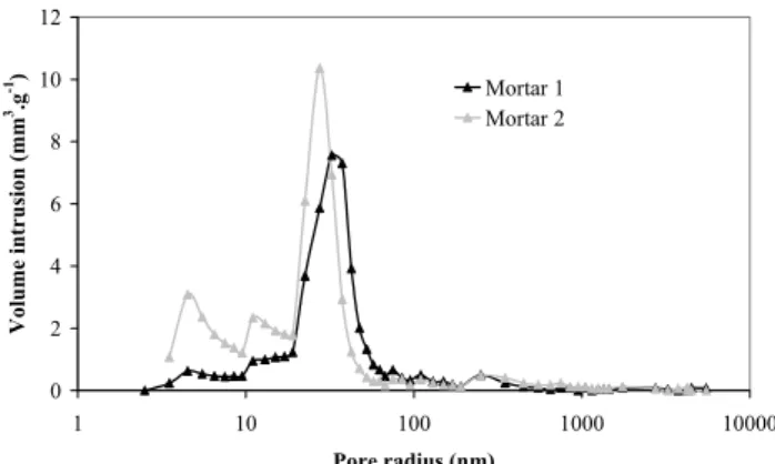
Considering the good reproduction of MIP measurements, a mean of mortars pore size distribution is represented in fig. 1. Figure 1 reveals that there is not a great difference with respect to curing cement’s addition in the pore size distribution over 100nm. But, the distribution of pores with radius of 3 to 50nm is different for the two materials.
For mortar 1, the maximum pore volume is found for 40nm. More than 50 percent of pores from the total porosity have their radius included between 25 and 50nm. The curve follows a single mode Gauss distribution. For mortar 2, this curve of pore size distribution is shift towards small pores radius: it presents two maxima for 35nm and 5nm. Two main modes of porosity are identified. Small pores with radius of 5 to 30nm are more abundant.
According to Powers classification (13), pores with a diameter from 100 up to 1000nm are the capillary pores. It can be remarked that they are more numerous in mortar 1.
Mortar 2 from cement blended with ash and slag contains more micro pores with radius less than 25nm than the mortar from ordinary Portland cement. This fine pore structure is due to pozzolanic reactions. As reported by Regourd (14), compared to plain cements, slag cement exhibits at later ages more pore in the 3 to 5nm size range. For fly ash cement, Cook and al. (15) observed that the pore structure consists mainly of pores nominally smaller than 25nm in pore radius.
These effects are confirmed by the results in table 6. The two porosities are similar, whereby the total specific surface area is more developed for mortar 2 which presents the smaller pore radius and the finest pore structure.
Pozzolanic reactions contribute to densify cement pastes by reducing capillary pores and created hydrates with lower gel porosity. The C/S ratio characteristic of the CSH is reduced for blended mortars because of the high silicium content in fly ashes and blast furnace slag.
As the microstructure determines transfer properties, gas permeability and chloride ion diffusion coefficient of these two mortars are expected to be different.
4.2 Transfer properties Gas permeability:
Gas permeability was found to be a strong function of the degree of saturation of the paste (16). Also, for a better evaluation, mortars are compared in dry state.
In practice situation, the engineered barrier would be entirely saturated with underground water of host formation after the close of the storage and would stay in this state
during his service life. So, mortars in dry conditions are not representative for the EBS service life but gas permeability measurement is used as a commonly indicator of durability (17, 18) and because it describes the pore connected into channel system.
This test (fig.2, table 7) does not allow us to distinguish the gas permeability for the two materials in significant way.
Literature findings generally agree with the concept that it is the larger pore fraction of the material that is responsible for determining gas permeability. These results lead us to suppose that the flow pathway, i.e. the pore connected fraction, responsible of the gas permeation is alike for the two mortars.
Chloride ions diffusion:
In regard to chloride ions diffusion tests, replacing ordinary Portland cement by blended cement with fly ash and slag reduces the chloride diffusion ability: the diffusion coefficient for mortar 2 five times fewer than the one obtained for mortar 1 (table 8). The diffusion of Cl- ions is
strongly influenced by the nature of cement. It has been observed by Malek and al. (19) that blended cement pastes with 30% fly ash by mass or 65% blast furnace slag by mass gave lower diffusion than Portland cement pastes from one order of magnitude.
This result is explained by the strong dependence of diffusion on smaller pores, their connectivity and tortuosity.
To summarize these characterization tests on mature sound mortars, which only differ from the nature of the cement, we can assume that they present similar fresh properties, comparable mechanical strengths and gas permeability. The finer microstructure developed by mineral additions provides lower chloride ions diffusion coefficient to mortar 2. As decalcification is based on diffusive process (3) it is waiting that chemical degradation and transfer properties modifications would be less effective for mortar 2.
5. Decalcification effects on mortars
5.1 Degraded depth
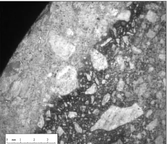
At each aggressive solution replacement, a sample was extracted from the aggressive medium to measure degraded depth on fracture sections sprayed with phenolphthalein with a video microscope (±50µm) (fig.3). The sample shows a sound core (represented in dark in the photograph, fig.4) and a peripheral altered porous zone in which portlandite is dissolved and CSH decalcified. Because of the presence of these two zones, degraded samples are named as “composite samples”.
This degraded depth determined by phenolphthalein spray is approximate: the equilibrium pH for coloration is around 9.5 (± 0.5), but it is considerate that the cement paste degradation begins for a pH value above portlandite equilibrium’s one: 12.5 (20).
In fact, the decalcification of cement hydrates appears to be more complex: the degraded depth could be separated in several zones relating to the gradient of calcium content and the variation of the C/S ratio of the CSH (3). For this first steps in our researches, we considerate the degraded depth as the global zone non colored by phenolphthalein.
Fig. 5 shows a nearly linear relation between the degradation depth (Ed in mm) and the square root of time of immersion, t, in day, where α represent an experimental coefficient:
These results demonstrate that the penetration of aggressive ions is described by a Fick’s diffusion process.
From the curves, α =1.72 for mortar 1 and α =1.73 for mortar 2: the evolution of degraded depth in time is similar for the two mortars and do not seems to be influence by the presence of fly ash and blast furnace slag. Nevertheless, considering table 9, the degraded thickness of the mortar 2 immersed during 86 days was 0.75 mm less than the depth measured for mortar 1 until 77 days. To obtain the same degraded depth, immersion time would be longer for mortar 1 than mortar 2. In fact, the leaching kinetic is strongly affected by experimental conditions and especially by the frequency at which we renew the attack solution and the duration of the period before the first renew. The establishment of the degradation process is faster for mortar 1 than in mortar 2 because of a greater diffusion coefficient that promotes the penetration of the aggressive ions from the solution to the material. Once the degradation has begun, the leaching was not more controlled by the aggressive solution/sound mortar interface but by the properties of the altered zone.
The amounts of calcium leached would help to evaluate the decalcification state of the mortars.
5.2 Calcium leaching
The removal of calcium ions from the material in the solid phase during the attack by the aggressive solution is monitored periodically by atomic absorption analysis at a wavelength of 418nm. In fig. 6, the amount of calcium leached is more important for mortar 1 than mortar 2. To really compare the two mortars, we have to pay attention to the fact that the concentration in calcium is higher in mortar 1: there is about 20% by mass more of CaO (table 1) in plain cement. The level headedness of calcium leached with initial calcium content (fig. 7) reveals that the attack dissolves comparable rectified quantities of calcium in time for the two mortars. This result illustrates the chemical equilibrium between calcium in solid phase Cas (mol) and
calcium in liquid phase Cal (mol) imposes by the chemical
reactions of dissolution (21): Cas/Cal is a constant ratio,
independent from the hydrates nature, balanced with decalcification reactions. Relatively to the initial calcium content, the altered zone in mortar 2 is more decalcified than in mortar 1.
t
Ed
=
α
5.3 Microstructure modifications
At the end of the attacks, samples were extracted from mortars 1 and 2 degraded zones for MIP investigations.
Figure 8 superposes the pore size distribution for sound and degraded mortar 1 samples. The main sound mode representative of a Gauss distribution is not any more present in degraded cementitious matrix: it is flattened and pore from many class of radius are present in the distribution.
Pore radius above 10nm are related to the gel of CSH: the first pores group observed on degraded mortars pore size distribution is due to the progressive decalcification of calcium silicates hydrates. The presence of numerous micro pores is confirmed by the high value of specific surface area (table 10). The second class is essentially composed with the lacks of dissolved large portlandite crystals (creation of empty space) that become part of the connected macroscopic porosity. Additionally, the pores of the main sound mode were converted into greater pores by the gradual widening with calcium released and the connections of these voids.
The main sound pores mode is shift towards greater radius pore size.
A similar comportment is observed for mortar 2 (table 10, fig. 9). From figure 9, two pores families are created in radius range of 50nm and 100nm and the main sound pore mode focused on 35nm has disappeared. The pozzolanic reactions consume portlandite to product CSH: paste of blended cement only comport few percent of calcium hydroxide. In spite of this fact, great pores are observed in deteriorated samples. It can be supposed that CSH decalcification and connection of channels are multiplied to balance the absence of portlandite.
As seen, gas permeability measurement reflects the macro porosity and the pathway of channels. The evolution of this parameter with decalcification would precise the former observations.
5.4 Decalcification impact on gas permeability
As attack was limited to radially degradation and as gas permeability value of the sound core was known (sound characterisation), a parallel model was applied to calculate the gas permeability of the altered zone. It is based on the hypothesis that the total gas flow through composite material is the sum of the flow through sound core (calculated with the sound characterisation coefficients) and the gas flow through peripheral degraded zone. These calculations are summarised in table 11 for mortar 1 and 2 and represent the average value from three tested samples for each mortar.
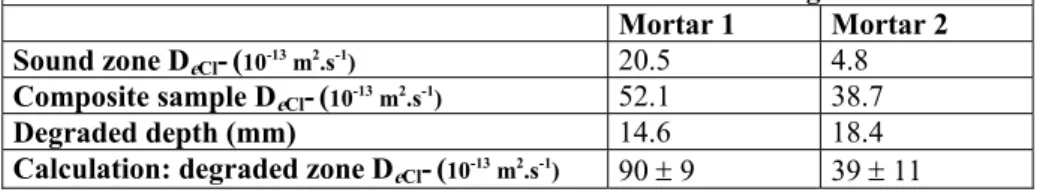
5.5 Decalcification impact on Chloride ions diffusion To calculate the diffusion coefficient in degraded zone with a parallel model we made the hypothesis that the amount of chloride ions diffusing through the sample is the sum of the
amount through the degraded zone and the quantity trough the sound core. Table 12 indicates the mean diffusion coefficient values from the measurement of three degraded mortar 1 and 2 samples.
It has been established that leaching consequence is an increase of the material porosity and then connection of macro pores and creation of nanoporosity in CSH gels when they are decalcified.
As expected, gas permeability is enhanced from two orders of magnitude when mortars are degraded but what is to notice is that gas permeability values are similar in degraded zones of the two mortars: the pathways created with decalcification are equivalent.
The effective chloride ions diffusion coefficient is multiplied by more than four for degraded mortar 1 and by and by about twenty for degraded mortar 2. The decalcification has more effect on the diffusion of mortar from blended cement by the nanoporosity and tortuosity modifications. The diffusion if the two mortars altered zones tends to be the same, despite the presence of mineral additions.
6. Discussion
To assess the influence of cement type on cementitious materials transfer properties decalcification, two mortars were prepared. Their mixtures only differ from the cement type: ordinary Portland cement for mortar 1 and blended cement with 22% by mass of fly ash and 22% by mass of blast furnace slag in mortar 2.
First statements are the variable microstructure resulting from the hydration of the selected cements. Fly ash and blast furnace slag addition to cement contributed to densify paste by developing of a finer pore structure. Similar trends have largely been reviewed: pozzolanic reactions promote CSH with lower C/S ratios which are more impenetrable and fill the large pores with hydration products.
Porosity governs transport through material. Therefore models use pore size distribution or mean pore radius to forecast transfer properties (22). Considering mortars microstructure different values could be attempt, but our results reveal more complex interactions.
In spite of the fact that gas permeability values are in the same order of magnitude for the two materials, the chloride ions diffusion coefficient is five time greater for mortar 1 than for mortar 2.
These variations could not be only attributing to the amount of pores: whereas mortar from blended cement has porosity to water greater than mortar 1, the former present lower chloride ions diffusion.
The difference in mechanism of mass transfer between the two tests involved may help to explain these results. Furthermore, microstructure could be described with various parameters: pore structure parameters or pore size distribution, whose differently influence transport through cementitious matrix.
The capillary porosity and the greater pores radius range are responsible for determining connected pathways and impose gas permeation. Whereas, chloride ions diffusion is function of all pore ranges of opening porosity and tortuosity of the cementitious matrix. Whereby, these different transfer mechanisms are not affected in the same way by the matrix microstructure: gas permeability is more influenced by macro pores whereas ionic transfer is more conditioned by form microstructure parameters like tortuosity or connectivity. As the connected pathway responsible for determining gas flow permeation is comparable for the two mortars, we didn’t observe difference on gas permeability for mortar 1 and 2. Mercury intrusion porosimetry shows differences in small pores radius range for the two mortars : the incorporation of fly ash and blast furnace slag promotes the formation of a discontinuous macro pores system which inhibits ionic flow but does not change gas permeability.
This study proves that microstructure effects on gas permeability and chloride diffusion should be counted separately.
In a second experimental phase, mortars comportment in hard aggressive medium has been examined. Samples were immersed in ammonium nitrate solution maintained at 25°C and pH 7 for periods up to 77 days for mortar 1 and 151 days for mortar 2.
The difference observed in degraded depth measurements for the same time of degradation between the two mortars could be attributed to the establishment of decalcification during the period before the first renew while decalcification processes are governed by the interface aggressive solution/sound mortar. Once the degradation regime is achieved, evolution of degradation depth with time in the strong aggressive conditions selected for our experiments seems to be the same for mortar 1 and 2. In the degraded zone, the transfer of dissolved species is controlled by diffusion of the altered cementitious matrix which seems to be very close for the two studied mortars during dynamic chemical degradation. In spite of the initial different microstructure and diffusivity, the permeation through the two degraded mortars tends to be comparable when a high decalcification in altered zone is attempt.
Calcium titration in attack solution suppose a greater leaching for mortar 1 than mortar 2. But these results have to be balanced by initial calcium content in the cementitious matrix of the two mortars and by the nature of the hydrates. For mortar 1, only 51% of the calcium present in the degraded zone is leached whereas 62% for mortar 2 is (mean values). We have to pay attention with this results, as far as the decalcification of limestone aggregates is not well estimated. Complementary studies performed on mortars with siliceous aggregates and the same cement would help us to discriminate the part of calcium leached from aggregates in the total amount of calcium in aggressive solution.
These different behaviors to aggressive ammonium nitrate attack should be interpreted as different decalcification reactions governed by mass transfer in a porous medium. Also, it’s necessary to consider the physical and chemical parameters that influence mass transfer through the studied mortars.
The key point is the chemical equilibrium between calcium in solid phase and calcium in aqueous phase (pore solution). Below this equilibrium concentration, calcium is dissolved involving different compounds of the solid matrix: calcium hydroxide crystals and calcium bound in the calcium silicate hydrates.
The constant of dissolution, as calcium disposability, depends on the nature of the chemical species involved. Calcium hydroxide is well dissolved (s=1.23g.l-1 at 20°C),
compared to CSH where calcium is stronger bound and needs more energy to dissociate. Almost, the solubility, i.e. calcium accessibility, of CSH varies with the C/S ratio: the more ratio higher, lower the solubility.
The type of calcium silicate hydrates are not the same in the two mortars: blended cement with fly ash and blast furnace slag contain more silica, so the CSH ratio C/S is between 0.85 and 1.5, whereas it is about 1.5 to 2 for ordinary Portland cement (23). The leaching process of cement based materials by ammonium nitrate solution induces a total leaching of Ca(OH)2 and a progressive
decalcification of CSH. As fly ash and blast furnace slag provide cementitious matrix poor of calcium hydroxide, the chemical attack is different and the CSH are directly decalcified.
Regarding to the initial calcium content, as the evolution with time of degraded depth is the same for the two materials; it can be argued that the progressive CSH decalcification leached less calcium in mortar 1 than mortar 2. Proportionally, mortar 2 is more attacked.
These observations are confirmed by MIP measurements in degraded zone. The space occupied by large portlandite crystal in mortar 1 became after dissolution part of the connected macroscopic porosity, which has a great effect on the total increase of cumulative volume, specific area and porosity. On the contrary, the decalcification of CSH in mortar 1 has less effect because it developed micro porosity (CSH gel). Carde (24) calculated that the porosity increase linked to the decalcification of the CSH only represents about 35% of the total gain. Ulm (25) affirmed that the dissolution of the calcium bound in the CSH chains does not create a discontinuity of the microscopic solid phase, nor the nanoporosity.
To finish, degradation impact on transport properties was considerate.
Previous studies focused on modeling establishment of diffusivity evolution with decalcification through porosity values (21).
According to Marchand and al. (26), the main effect on plain cement pastes is due to calcium hydroxide dissolution (the diffusion coefficient is multiplied by 22.4), whereas supplementary dissolutions of Afm and Aft systems only increase diffusivity from respectively 22.7 and 29.7.
Kamali (27) confirmed Marchand’s results and remarked that silica fume additions in cement significatively reduce the diffusion coefficient for sound samples nevertheless do not show very different diffusivity for degraded ones compared to standard specimens. This affirmations are confirmed by our results of diffusion on degraded mortars. From Bentz and al. (28), the pore space percolation characteristics and relative ionic diffusivity are compared through the leaching process as a function of the capillary porosity. They used the concept of a critical volume
fraction of Ca(OH)2 linked to capillary pore space
(diameter>1µm) in percolation theory to determine the magnitude of the leaching effect on diffusivity. Once the capillary pore space reconnected, the diffusivity increases much more rapidly with an increase in diameter. It could explain the similitude for diffusivity in degraded materials with or without addition whereas this characteristics is very different for the sound materials.
We decided to performed gas permeability measurements, first as an indicator of the state of altered mortars macro porosity and of the changes in greater pore channels occurred with decalcification action of ammonium nitrate and secondly to compare permeation behaviour in degraded mortars to diffusive one.
The results confirm the similarity between the two degraded mortars gas permeability. Cui (29) affirmed that pore whose diameter <30nm do not affect much of permeability. The capillary porosity is equivalent for the two degraded mortars. If the curve of the connected fraction in function to capillary porosity is considerate (28), it seems to be evident that for such porosity in degraded zones, percolation thresholds are created for the two mortars and induce similar high permeability.
7. Conclusions
• Mercury intrusion porosimetry confirms that fly ash and blast furnace slag additions leads to a finer pore structure for cement paste.
• Mineral additions do not influence permeability to gas of the mortars.
• The accelerated chloride ions diffusion tests reveals the benefit from the use of mineral additions in hindering chloride penetration in mortars.
• Transfer properties are both mainly affected by the microstructure but in different manners: the gas permeability is linked to the percolation way since diffusion depends on the pore size distribution and porosity tortuosity.
• The evolution of degraded depth with time is
comparable for the two materials.
• Proportionally to the initial calcium content, mortar 2 is less resistant to chemical degradation.
• The determination of calcium leaching with time isn’t sufficient to evaluate the resistance to chemical attack of a material; more characteristics have to be taken into account. For example, the evolution of the CSH C/S ratio or microstructure evolution and the influence on transfer properties.
• Chemical degradation is governed by diffusive process. Despite the lower diffusion coefficient of sound mortar 2, this material is almost more degraded. Therefore, transfer properties of native mortars could not be used to predict the comportment versus chemical attack.
• Fly ash and blast furnace slag provide better properties for native mortars, and more principally diffusion properties, but not as much as necessary to limit leaching in degraded material by chemical attack. When a high value of decalcification is reached, transfert properties of the two mortars tend to be similar.
Acknowledgments
The authors are grateful to the “Agence Nationale pour la gestion des déchets radioactifs” (ANDRA) for financial support.
8. References
[1]. Calibé, ‘Projet national Calibé. Suivi rhéologique sur mortier de béton équivalent MBE’, IREX, Paris (2000). [2]. Tognazzi C., ‘Couplage fissuration-dégradation chimique dans les matériaux cimentaires ; caractérisation et modellisation’, Ph.D INSA Toulouse (1998).
[3] Adenot F., ‘Durabilité du béton : caractérisation et modélisation des processus physiques et chimiques de dégradation du ciment’, Ph.D. thesis, INSA Toulouse, France (1992).
[4]. Day R.L., Konecny L., ‘Relationship between permeability and Microstructural characteristics of fly ash mortars’, Materials Research Society Symposium Proceedings: Pore structure and permeability of cementitious materials, Ed. Roberts L.R., Skalny J.P., 137, (1989) 391-402.
[5]. AFPC-AFREM, ‘Détermination de la masse
volumique apparente et de la porosité accessible à l’eau’, Méthodes recommandées pour la mesure des grandeurs associées à la durabilité. Compte rendu des journées techniques AFPC-AFREM’, p. 121-124, Toulouse (1997). [6]. Kollek J.J., ‘The determination of the permeability of concrete to oxygen gas by the Cembureau method- a recommendation’, Materials and Structures, 22 (1989) 225-230.
[7]. Lydon F.D., ‘Effect of coarse aggregate and water/cement ratio on intrinsic permeability of concrete subject to drying’, Cement and Concrete Research, 25, (1995) 1737-1746.
[8]. Carcassès M., Abbas A., Ollivier J-P., Verdier J., ‘An optimised preconditionnal procedure for gas permeability measurement’, Materials and Structure, 35, (2001) 22-27. [9]. Truc O., Ollivier J-P., Carcassès M., ‘A new way for determining the chloride diffusion coefficient in concrete from steady state migration test’, Cement and Concrete Research, 30, (2000) 217-226.
[10].Carde C., ‘Caractérisation et modélisation de l’altération des propriétés due à la lixiviation des matériaux cimentaires’, Ph.D thesis INSA Toulouse (1997).
[11]. Schneider U., Chen S-W., ‘Influence of concentration of ammonium nitrate solutions on concrete’, Sixth CANMET/ACI International Conference on Durability of Concrete, Thessaloniki, (2003) 439-447.
[12]. Targan S., Olgun A., Erdigan Y., Sevinc V., ‘Influence of natural pozzolan, colemanite ore waste, bottom ash and fly ash on the properties of Portland cement’, Cement and Concrete Research, 33, (2003) 1175-1182.
[13]. Powers T.C., Browntard T.L., ‘Studies of the physical properties of hardened Portland Cement Paste’, ACI Journals Proceedings, Part VII., 43, (1947) 933-992.
[14]. Regourd M., ‘Microstructure of cement blends containing fly ash, silica fume, slag and fillers’, Materials Research Society, 85, Symposia proceedings : Microstructural development during hydration cement, L. J. Struble, P. W. Brown, (1987) 187-199.
[15]. Cook D. J., Cao H. T., Coan E. P., ‘Pore structure development in Portland/fly ash blends’, Materials Research Society, 85, Symposia proceedings: Microstructural development during hydration cement, L.J. Struble, P.W. Brown, (1987) 201-213.
[16]. Abbas A., Carcassès M., Olliver J-P., ‘Gas permeability of concrete in relation to its degree of saturation’, Material and Structure, 32, (1999) 3-8.
[17]. AFGC, ‘Conception des bétons pour une durée de vie donnée des ouvrages’ Documents scientifiques et technique (2004).
[18]. Kearsley E.P., Wainwright P.J., ‘Porosity and permeability of foamed concrete’, Cement and Concrete Research, 31, (2001) 805-812.
[19]. Malek R. I. A., Roy D. M., Licastro P. H., ‘The diffusion of chloride ions in fly ash cement pastes and mortars’, Materials Research Society, 85, Symposia proceedings: Microstructural development during hydration cement, L.J. Struble, P.W.Brown, (1987) 223-233.
[20]. Le Bellego C., ‘Couplage chimie-mécanique dans les structures en béton attaquées par l’eau : étude expérimentale et analyse numérique’, Ph.D. thesis École normale supérieure de Cachan (2001).
[21]. Mainguy M., Tognazzi C., Torrenti J-M., Adenot F., ‘Modelling of leaching in pure cement paste and mortar’, Cement and Concrete Research, 30, (2000) 83-90.
[22]. Bagel L., Zivica V., ‘Relationship between pore structure and permeability of hardened cement mortars: on the choice of effective pore structure parameter’, Cement and Concrete Research, Vol. 27, N°8, p. 1225-1235 (1997). [23]. Richardson I.G., ‘The nature of CSH in hardened cements’, Cement and Concrete Research, Vol. 29, p. 1131-1147 (1999).
[24]. Carde C., Francois R., `Effect of ITZ Leaching on durability of cement-based materials’, Cement and Concrete Research, 27, N°7, (1997) 971-978.
[25]. Ulm F-J., Lemarchand E., Heukamp F.H., ‘Elements of chemomechanics of calcium leaching of cement based materials at different scales’, Engineering Fracture Mechanics, 70, (2003) 871-889.
[26]. Marchand J., Bentz D., Samson E., Maltais Y., ‘Influence of calcium hydroxide dissolution on the transport properties of hydrated cements systems’, Reactions of
calcium hydroxide in concrete’, American Ceramic Society, Westerville (2001).
[27]. Kamali S., ‘Comportement et simulation des matériaux cimentaires en environnements agressifs : lixiviation et température’, Ph.D thesis ENS Cachan (2003). [28]. Bentz D.P., Garboczi E.J., ‘Modelling the leaching of calcium hydroxide from cement paste: effects on pore space percolation and diffusivity’ Material and Structure, 25, (1992) 523-533.
[29].Cui L., Herman Cahyadi J., ‘Permeability and pore structure of OPC past’, Cement and Concrete Research, 31, (2001) 277-282.
Table 1- Chemical composition of CEM I and CEM V/A cements.
Element (% by mass) CEM I CEM V/A
SiO2 21.2 29.4 Al2O3 3.5 11.4 Fe2O3 4.6 3.20 CaO 64.6 46.4 MgO 0.6 3.02 K2O 0.63 1.06 Na2O 0.17 0.21 SO3 2.65 2.81 TiO2 No detected 0.64 MnO No detected 0.11
Table 2 - Potential cement composition from clinker (Bogue’s formule).
Clinker component (%) CEM I CEM V/A
C3S 57.0 59.8
C2S 16.6 15.8
C3A 1.5 7.2
C4AF 14.0 10.7
Table 3 - Mixtures of mortars studied.
Constituant (kg.m-3) Mortar 1 Mortar 2
Cement 1: CEM I 52.5 PM-ES, Val d’Azergues, Lafarge 618
Cement 2: CEM V/A 42.5 R PM-ES, Airvault, Calcia 682
Limestone sand 0/4 mm, Boulonnais 1365 1253
Superplastizier 6 7
Efficace water 264 280
Total 2253 2221
W/C (water/cement) 0.40 0.42
C/A (Cement/Aggregate) 0.45 0.54
Table 4 – Fresh and mechanical properties of mortars 1 and 2.
Characteristic Experimental method Mortar 1 Mortar 2
Slump (cm) Slump test 20 (total) 20 (total)
Workability (s) «Maniabilimètre à mortier» (NF P 18-452) 4 2
Density (kg.m-3) Hydrostatic weighing 2288 2260
Air content (%) Air content apparatus 2.2 2.3
Flexural strength (MPa) 10 ± 1 10 ± 1 Compressive strength (MPa) EN 196-1 78 ± 3 87 ± 2
Table 5 - Water porosity measurements.
Mortar 1 Mortar 2
Bulk density (kg.m-3) 2145 2045
Water porosity (%) 19.7 22.0
Table 6 - Global results for mercury intrusion porosity. Mortar 1 Mortar 2
Total specific surface area (m2.g-1) 5.4 7.3
Average pore radius (nm) 37 28
0 2 4 6 8 10 12 1 10 100 1000 10000 Pore radius (nm) Volume intrusion (mm 3.g -1) Mortar 1 Mortar 2
Fig. 1- Effect of cement type on pore size distribution.
3,5E-17 4,5E-17 5,5E-17 6,5E-17 7,5E-17 8,5E-17
2,5E-06 3,5E-06 4,5E-06 5,5E-06 6,5E-06 7,5E-06
1/Pm (Pa-1) ka ( m ²) Mortar 1 Mortar 2
Fig. 2 - Gas permeability in dry state for mortar 1 and 2.
Table 7 - Mean permeability results for mortar 1 and 2. Mortar 1 k0%,0.25 (.10-18 m²) Mortar 2 k0%,0.25 (.10-18 m²) Sample 1 62.9 44.7 Sample 2 51.9 52.4 Sample 3 54.6 59.0 Sample 4 49.9 69.2 Mean value 54.8 ± 6 56.3 ± 10
Table 8 - Chloride ions diffusion coefficient for mortar 1 and 2. DeCl- average (10-13 m2.s-1)
Mortar 1 20.5 ± 2
Mortar 2 4.8 ± 0.7
Table 9 - Degraded depth measurements.
Mortar 1 Mortar 2
Aggressive test period (day) Degraded depth (mm) Aggressive test period (day) Degraded depth (mm)
8 4.23 12 3.85 18 6.42 32 6.60 28 8.30 45 7.86 40 10.38 67 10.69 55 11.59 86 13.71 77 14.46 151 18.37
Fig. 3 - Videomicroscope image of mortar 1degraded depth.
Fig. 4 – Mortar 1 degraded depth evolution with immersion time.
0 1 2 3
0 20 40 60 80 100 120 140 160
Degradation duration (day)
[Ca 2+] (mo l.l -1.m -2) Mortar 1 Mortar 2
Fig. 6 - Calcium leached during attack of mortar 1 and 2.
Mortar 1 y = 1,72j1/2 Mortar 2 y = 1,73j1/2 0 2 4 6 8 10 12 14 16 18 20 0 2 4 6 8 10 12 14
Degradation duration (day 1/2)
De gr ade d de pt h ( m m ) Mortar 1 Mortar 2
Fig. 5 - Degraded depth versus aggressive period.
0,4 0,5 0,6 0,7 0,8 0 2 4 6 8 10 12 14
Degradation duration (day1/2)
Ca le ac h ed /in itial Ca c on te n t (mol/mol) Mortar 1 Mortar 2
Fig. 7- Evolution of the calcium leached relatively to calcium initial content with time.
0 2 4 6 8 10 12 14 16 1 10 100 1000 10000 Pore radius (nm) Volume intrusion (mm 3 .g -1 ) Sound mortar 1 Degraded mortar 1
Fig. 8- Pore size distribution comparison between sound and degraded zone of mortar 1.
0 2 4 6 8 10 12 14 16 1 10 100 1000 10000 Pore radius (nm) Int rusi on vol ume ( m m 3 .g -1 ) Mortar 1 degraded Mortar 2 degraded
Fig. 9- Pore size distribution comparison of degraded mortar 1 and 2.
Table 10 - Global results for mercury intrusion porosity for sound and degraded mortars.
Mortar 1 Mortar 2
Sound Degraded Sound Degraded
Total specific surface area (m2.g-1) 5.4 15.3 7.3 17.7
Average pore radius (nm) 37 236 28 61.3
Table 11 – Gas permeability calculation of mortar degraded zones.
Mortar 1 Mortar 2
Sound zone k0%,0.25 (.10-18 m²) 55 56
Composite sample k0%,0.25 (.10-18 m²) 500 850
Degraded depth (mm) 14.6 18.4
Calculation: degraded zone k0%,0.25 (.10-18 m²) 1340 ± 90 1853 ± 155
Table 12 – Chloride ions diffusion calculation of mortar degraded zones.
Mortar 1 Mortar 2
Sound zone DeCl-(10-13 m2.s-1) 20.5 4.8
Composite sample DeCl-(10-13 m2.s-1) 52.1 38.7
Degraded depth (mm) 14.6 18.4