CHEMICAL LOOPING GASIFICATION OF BIOMASS
MILAD AGHABARARNEJAD DÉPARTEMENT DE GÉNIE CHIMIQUE ÉCOLE POLYTECHNIQUE DE MONTRÉAL
THÈSE PRÉSENTÉE EN VUE DE L’OBTENTION DU DIPLÔME DE PHILOSOPHIÆ DOCTOR
(GÉNIE CHIMIQUE) AOÛT 2014
c
ÉCOLE POLYTECHNIQUE DE MONTRÉAL
Cette thèse intitulée :
CHEMICAL LOOPING GASIFICATION OF BIOMASS
présentée par : AGHABARARNEJAD Milad
en vue de l’obtention du diplôme de : Philosophiæ Doctor a été dûment acceptée par le jury d’examen constitué de :
M. STUART Paul, Ph.D., président
M. CHAOUKI Jamal, Ph.D., membre et directeur de recherche
M. PATIENCE Gregory S., Ph.D., membre et codirecteur de recherche M. LEGROS Robert, Ph.D., membre
DEDICATION
ACKNOWLEDGMENTS
First of all, I would like to express my deep and sincere gratitude to my supervisor, Prof. Jamal Chaouki. His wide knowledge and his logical way of thinking, encouragements, advices, and guidance have been great value for me.
I am deeply grateful to my co-supervisor, Prof. Gregory S. Patience, for his detailed and con-structive comments, and for his important support, encouragement, advices throughout this work.
Special thanks to the technical staff of the chemical engineering department, especially Mr. Robert Delisle, Mr. Yazid Belkhir, Mr. Jean Huard and Ms. Martine Lamarche.
I would like to extend my thanks to all my colleagues in Prof. Chaouki group for sharing knowledge and ideas. I am thankful to Ms. Odile Vekemans for translation a part of this thesis to French. Many thanks also to all my friends Mahsa, Majid, Amin, Jaber, Hamed, Pierre-Phillipe, Abbas, Alireza ... for all the unforgettable moments which I had with them.
My special gratitude is due to my father, mother and brothers and their families for their lovely support and encouragement.
RÉSUMÉ
La gazéification à la vapeur de la biomasse est une réaction endothermique dont l’énergie néces-saire peut être fournie soit par une source externe, soit par combustion d’une partie de la biomasse par de l’oxygène. Parmi les différentes sources d’oxygène on trouve l’air, qui entraine la dilution du gaz de synthèse dans l’azote, et l’oxygène pur, qui augmente fortement les coûts totaux de pro-duction. Une alternative à l’air et à l’oxygène pur est le procédé de boucle chimique. Dans ledit procédé, l’oxygène est séparé de l’air à haute température à l’aide d’oxydes métalliques. Dans un premier réacteur, appelé réacteur d’oxydation, le métal réduit est oxydé par l’air. Ce métal oxydé est ensuite transféré dans un second réacteur, appelé gazogène, où il libère l’oxygène qui permet la combustion partielle de la biomasse. Ce métal une fois réduit est recyclé vers le réacteur d’oxyda-tion où il est régénéré. Afin d’augmenter la stabilité thermique et mécanique de l’oxyde métallique, il est supporté par un matériau à haute résistance et cette combinaison est appelée transporteur d’oxygène.
Comme dit précédemment, les transporteurs d’oxygène sont capables d’absorber l’oxygène de l’air et ensuite de le désorber dans le gazogène. En se basant sur des données thermodynamiques, les oxydes de cuivre, de manganèse et de cobalt, ont été identifiés comme ayant les capacités les plus élevées de libération de l’oxygène parmi les différents transporteurs d’oxygène potentiels. Ces derniers ont été déposés sur de l’alumine par imprégnation jusqu’à humidité naissante ou “Inci-pient Wetness Impregnation”. Des analyses thermogravimétriques ont permis d’évaluer la perte de poids du couple CuO-Cu2O à 10 % alors qu’elle n’était que de 7 % pour le couple Co3O4-CoO et 3 % pour le couple Mn2O3-Mn3O4. Néanmoins, la température optimale d’opération de CuO était de 950◦C, soit 100◦C de plus que celle des deux autres transporteurs. Un modèle modifié de croissance de noyau a été utilisé pour caractériser la perte et le gain de masse pendant les cycles d’oxydo-réduction de cobalt. A 875◦C, le taux de réduction est 3 fois supérieur à celui à 825◦C, alors que la vitesse d’oxydation diminue de plus de 10 fois. D’autre part, la surface spécifique du transporteur CuO diminue de 70 % alors qu’elle ne diminue que de 30 % et de 60 % pour les
transporteurs fait de Co3O4et de Mn2O3respectivement. Le cobalt a donc moins tendance à fritter à haute température par rapport au cuivre ou au manganèse, et ce couplé à une bonne capacité de transport d’oxygène et un bon taux d’oxydation-réduction. Par conséquent, en dépit de son coût élevé et de sa toxicité, l’oxyde de cobalt peut être considéré comme un transporteur d’oxygène potentiel pour la gazéification de combustibles solides.
Dans la seconde partie de la thèse, de la biomasse a été gazéifiée dans un lit fluidisé a bulles avec de la vapeur et de l’oxygène. Ce dernier était fourni par la réduction de Co3O4en CoO. L’oxyde de cobalt réduit (CoO) a ensuite été régénéré par substitution de la vapeur par de l’air et ce lors de l’interruption de l’alimentation de la biomasse. En modifiant la température de 825◦C à 875◦C, le rendement de H2a augmenté jusqu’à 60 %. En modifiant l’injection de vapeur de 0 à 18 %, le rendement de H2a augmenté de 4 fois. En remplaçant 50 % du sable qui constituait le lit avec du Co3O4, le rendement de CO a augmenté jusqu’à 45 % et le rapport H2:CO a été diminué. Afin de modéliser le réacteur, un modèle à deux phases pour le lit dense et un modèle d’écoulement piston pour la zone de projection ou “freeboard” ont été utilisés. Une des hypothèses adoptées dans ce mo-dèle est que les solides sont bien mélangés. Lors de l’augmentation de température de l’ambiance à 850◦C, le coefficient de dispersion axiale est augmenté de 0.09 à 0.12 m2/s. De plus, la variation de la composition du gaz dans la direction radiale est négligeable. Ce modèle hydrodynamique couplé à un modèle cinétique disponible dans la littérature caractérise adéquatement la composition des gaz à la sortie du réacteur.
Dans la partie finale de cette thèse, un système de gazéification conventionnel (CG) et un sys-tème de gazéification en boucle chimique (CLG) pour le traitement de 86 t/j de biomasse ont été simulés avec Aspen Plus et leurs coûts d’exploitation et de capital ont été comparés. A l’exception de la configuration du réacteur, ces deux systèmes sont identiques. Le réacteur CG est composé d’un lit fluidisé a bulles (ID = 1.8 m, et H = 6.6 m) qui sert de gazogène, dont le lit est composé de sable, et l’oxygène est fourni par l’intermédiaire d’une unité de modulation de pression d’adsorp-tion. Le CLG, quant à lui, se compose d’un gazogène à lit fluidisé dense (ID = 1.8 m, et H = 6.6 m et) travaillant en parallèle avec un réacteur d’oxydation à lit fluidisé rapide (ID = 1 m, et H = 10 m).
Un débit de Co3O4(8 %)/Al2O3 de 44.6 kg /s passe du gazogène au réacteur d’oxydation, et per-met de fournir l’oxygène nécessaire à la gazéification. L’investissement total en capital (ITC) des unités CG et CLG sont estimées à 6.3 et $9.7M respectivement. Cependant, les coûts de production annuels du CLG sont de $0.58M de moins que la CG, permettant de rembourser la différence en capital du TCI en moins de 6 ans.
ABSTRACT
The steam gasification of biomass is endothermic. The energy can be supplied either by an external source or by combusting a part of biomass feed with oxygen. Air dilutes the produced syngas with nitrogen; while, pure oxygen increases the total production cost. Besides air and pure oxygen, the chemical looping process is an alternative to provide the required oxygen. Using the chemical looping system, the produced syngas has a higher calorific value compared to a conven-tional biomass gasification process with air. The oxygen is separated from air at high temperature using metallic oxides. The reduced metal is oxidized with air and transferred to the reducer where it releases oxygen. The reduced metal oxide is recycled to the oxidizer for regeneration, and the released oxygen in the reducer is available in the gaseous form to combust or gasify the biomass. To increase the thermal and mechanical stability of the metal oxide, it is supported with a high strength material, and in combination is called an oxygen carrier.
Oxygen carriers for biomass gasification are capable of absorbing oxygen from air and desorb-ing it in the gasifier. Based on thermodynamic equilibrium, copper, manganese and cobalt oxides have the highest oxygen release capacities among the different oxygen carriers. These oxygen carriers were deposited on alumina via incipient wetness impregnation. The weight loss of the CuO-Cu2O carrier, as measured in a thermo-gravimetric analyzer, was 10 %, while it was 7 %, for the Co3O4-CoO couple, and only 3 % for the Mn2O3-Mn3O4 couple. The optimum operating temperature for the CuO oxygen carrier was 100◦C higher compared to the other two at 950◦C. A modified nuclei growth model (MNG) characterizes the weight loss/gain during the reduction-oxidation cycles. The reduction rate is 3 times higher at 875◦C compared to 825◦C, while, the ox-idation rate decreases more than 10 times. The CuO carrier surface area decreased by 70 %, while it was 30 % and 60 % in the Co3O4and Mn2O3carriers, respectively. Cobalt has a lower tendency to sinter at high temperature compared to either copper or manganese and has a higher oxygen transport capacity and oxidation-reduction rates. Therefore, despite its higher cost and toxicity it might be considered as a potential oxygen carrier especially for solid fuel gasification.
As the second part of the thesis, biomass was gasified in a bubbling fluidized bed with steam and oxygen. The oxygen was supplied by reducing Co3O4to CoO. The reduced cobalt oxide (CoO) was regenerated by switching the fluidizing gas to air. This technology known as chemical looping, is to combust or gasify fuels. The effluent gas is free of nitrogen and has a higher calorific value compared to gasification with air. From 825 to 875◦C, H2 yield increased up to 60 %. From 0 to 18 % of steam, H2 yield increased 4 times. Substituting 50 % of the sand as bed material with Co3O4, increased the CO yield up to 45 %, while lowering the H2:CO ratio. A two phase model for the dense bed and a plug flow model for the freeboard region were used for reactor modeling. The solids were assumed to be well mixed. From ambient to 850◦C, the axial dispersion coefficient increased from 0.09 to 0.12 m2/s. Furthermore, the difference between the gas composition in the radial direction was negligible. The presented hydrodynamic model together with the kinetic expression from the literature characterized the transient gas compositions at the reactor outlet very well.
In the final stage of this thesis, a conventional gasification (CG) system and a chemical looping gasification (CLG) system to treat 86 t/d biomass were simulated with Aspen Plus and the operating and capital cost of them were compared. Conventional gasification (CG) systems use air as an oxygen source. Besides air, the chemical looping process is an alternative method to provide the system with the required oxygen. The syngas produced using the chemical looping has a higher calorific value than that produced using a conventional process with air. For comparison purposes, a conventional gasification unit with pure oxygen (CGPO) and a chemical looping gasification (CLG) system were simulated using Aspen Plus to treat 86 t/d biomass, and an economic analysis comparing the operating and capital costs of the two systems was performed. The two systems were identical except for the reactor configuration. The “CGPO” reactor consisted of a bubbling fluidized bed (ID=1.8 m and H=6.6 m) as gasifier and sand as bed material with oxygen supplied via a pressure swing adsorption unit. The CLG consisted of a bubbling fluidized bed gasifier (ID=1.8 m and H=6.6 m) working in parallel with a fast fluidized bed oxidizer (ID=1 m and H=10 m). Co3O4(8 %)/Al2O3 with a circulation rate of 44.6 kg/s between gasifier and oxidizer supplied the
oxygen for the CLG system. The total capital investment (TCI) of the CGPO and CLG units were $6.3M and $9.7M, respectively. However, the annual operating cost of the CLG was $0.58M less than that of the CGPO which repays the difference in TCI in less than 6 years.
Milad Aghabararnejad
École Polytechnique de Montréal July 2014
TABLE OF CONTENTS DEDICATION . . . iii ACKNOWLEDGMENTS . . . iv RÉSUMÉ . . . v ABSTRACT . . . viii TABLE OF CONTENTS . . . xi LIST OF TABLES . . . xv
LIST OF FIGURES . . . xvi
CHAPTER 1 INTRODUCTION . . . 1
CHAPTER 2 LITERATURE REVIEW . . . 4
2.1 Introduction . . . 4 2.1.1 Biomass . . . 5 2.2 Biomass conversion . . . 7 2.2.1 Chemical conversion . . . 7 2.2.2 Biochemical conversion . . . 8 2.2.3 Thermal conversion . . . 8 2.3 Syngas cleaning . . . 14
2.4 Air separation units (ASU) . . . 18
2.4.1 Cryogenic systems . . . 18
2.4.2 Adsorption systems . . . 18
2.5 Preparation of the oxygen carrier . . . 21
2.5.1 Mechanical mixing . . . 21
2.5.2 Wet impregnation . . . 21
2.5.3 Incipient wetness impregnation . . . 21
2.5.4 Co-precipitation . . . 22
2.5.5 Freeze granulation . . . 22
2.6 Chemical looping combustion-CLC . . . 23
2.7 Chemical looping process for H2production . . . 26
2.8 Chemical looping Gasification-CLG . . . 29
2.9 Summary . . . 31
CHAPTER 3 COHERENCE OF THE ARTICLES . . . 33
CHAPTER 4 ARTICLE 1: TGA AND KINETIC MODELING OF Co, Mn, AND Cu OXIDES FOR CHEMICAL LOOPING GASIFICATION (CLG) . . . 35
4.1 Introduction . . . 36
4.1.1 Process description . . . 37
4.1.2 Solid fuel gasification in chemical looping systems . . . 39
4.2 Experiment . . . 43
4.2.1 Materials . . . 43
4.2.2 Methods and techniques . . . 44
4.3 Results and discussion . . . 45
4.3.1 Oxygen release capacity by TGA . . . 45
4.3.2 Reduction and oxidation kinetic . . . 49
4.3.3 XRD results . . . 54
4.3.4 Thermal resistance of the oxygen carrier . . . 55
4.3.5 The interaction between Co3O4and biomass . . . 56
References . . . 59
CHAPTER 5 ARTICLE 2: TRANSIENT MODELING OF BIOMASS STEAM GASIFICA-TION WITH Co3O4 . . . 62
5.1 Introduction . . . 63
5.2 Materials, methods and experiments . . . 67
5.3 Steam gasification model . . . 71
5.3.1 Oxygen desorption in a bubbling fluidized bed . . . 72
5.3.2 Biomass pyrolysis . . . 75
5.3.3 Steam gasification . . . 76
5.3.4 Homogeneous gas phase reactions . . . 77
5.4 Results and discussion . . . 78
5.4.1 Hydrodynamic model validation . . . 78
5.4.2 Oxygen desorption in a bubbling fluidized bed . . . 81
5.4.3 Effect of temperature . . . 83
5.4.4 Effect of steam . . . 85
5.4.5 Effect of Co3O4 . . . 86
5.5 Conclusions . . . 88
References . . . 89
CHAPTER 6 ARTICLE 3: TECHNO-ECONOMIC COMPARSION OF A 7 MWth BIO-MASS CHEMICAL LOOPING GASIFICATION UNIT WITH CONVENTIONAL SYS-TEMS . . . 97
6.1 Introduction . . . 98
6.2 Design and simulation of the CG unit . . . 101
6.3 Design and simulation of the CLG unit . . . 109
6.3.1 Gasifier . . . 111
6.4 Economic analysis of CG, CGPO, and CLG units . . . 114
6.4.1 Capital cost . . . 114
6.4.2 Total production cost (TPC) . . . 115
6.5 Conclusions . . . 118
References . . . 123
CHAPTER 7 GENERAL DISSCUSSION . . . 127
CHAPTER 8 CONCLUSIONS AND RECOMMENDATIONS . . . 134
8.1 Conclusions . . . 134
8.2 Recommendations . . . 137
LIST OF TABLES
Table 2.1 Operating CLC system . . . 27
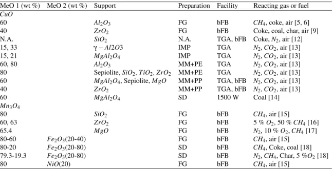
Table 4.1 Summary of oxygen-carrier particles prepared and tested for CLOU appli-cation . . . 42
Table 4.2 Incipient wetness impregnation for preparation of supported oxygen carrier 43 Table 4.3 Biomass elemental and proximate analysis . . . 43
Table 4.4 Activation energy for copper, cobalt and manganese reduction and oxidation 53 Table 5.1 Equilibrium and kinetic models of gasification . . . 66
Table 5.2 Physical properties of Co3O4 . . . 68
Table 5.3 Biomass elemental and proximate analysis . . . 68
Table 5.4 The experimental plan for the gas phase RTD . . . 70
Table 5.5 Experimental plan for steam gasification of biomass . . . 71
Table 5.6 State equations and hydrodynamic parameter for a two phase model . . . . 74
Table 5.7 Kinetic parameter of Sweet Gum pyrolysis, Nunn et al. [29] . . . 75
Table 5.8 Gas solid reactions at the bed surface . . . 77
Table 5.9 Gas phase reaction rate expressions (mol/m3.s) . . . 78
Table 6.1 Design of the chemical looping processes . . . 100
Table 6.2 Mass balance of the CG unit, Aspen plus V. 7.2 . . . 104
Table 6.3 Mass balance of the CGPO unit, Aspen plus V. 7.2 . . . 104
Table 6.4 Simulation description of CG and CGPO units . . . 105
Table 6.5 CG and CGPO gasifier design results . . . 108
Table 6.6 Mass balance of the CLG, Aspen plus V. 7.2 . . . 110
Table 6.7 Simulation description of CLG system . . . 110
Table 6.8 Oxidizer design results (CLG unit) . . . 114
LIST OF FIGURES
Figure 2.1 Comparison of the world energy resources in 2011 and 2030 . . . 4
Figure 2.2 Carbon cycle . . . 6
Figure 2.3 Methods of biomass conversion to fuel, gases and chemicals . . . 7
Figure 2.4 World syngas market in 2004 . . . 11
Figure 2.5 Pressure swing adsorption, bed 1 in regeneration, bed 2 in process, P2>P1 . 19 Figure 2.6 Chemical looping combustion of gaseous fuels . . . 24
Figure 2.7 in situ gasification-chemical looping combustion process . . . 25
Figure 2.8 Chemical looping oxygen uncoupling process . . . 25
Figure 2.9 Chemical looping water splitting for hydrogen production . . . 28
Figure 2.10 The Fast Internally Circulating Fluidized Bed (FICFB) gasification system, the arrows correspond to the solid circulation between two sections . . . . 30
Figure 4.1 Circulating fluidized bed gasifier, the arrows correspond to the solid circu-lation between two sections . . . 38
Figure 4.2 Mechanisms of iG-CLC and CLOU (Modified from Adanez et al. . . 40
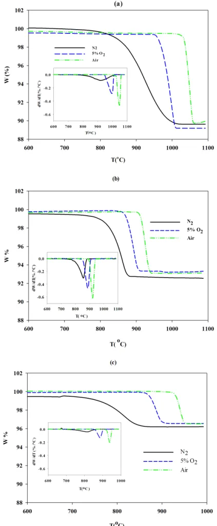
Figure 4.3 The profile of weight loss and rate with temperature in (0%, 5% and 21% O2) for a) CuO, b) Co3O4, and c) Mn2O3 . . . 46
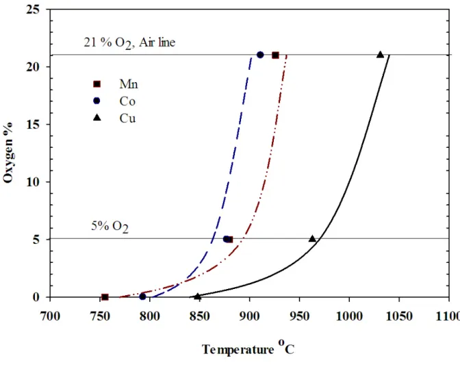
Figure 4.4 The initial temperature of reduction in different oxygen concentrations, Ex-perimental data and equilibrium curve by FactSage 6.4 software, Cu (—— ), Mn (– ·· –), Co (– – –) . . . 48
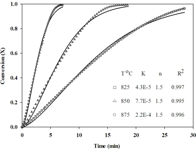
Figure 4.5 Co3O4 reduction in nitrogen, conversion vs time at 825, 850 and 875◦C, the solid line represents the model) . . . 51
Figure 4.6 CoO oxidation in air, conversion vs time at 825, 850 and 875◦C, (- - - - ) NG model, ( —— ) MNG model (modified NG model, Equation 4.13) . . . 52
Figure 4.7 Arrhenius relationship of KOxi (from MNG model) and KRed with tempe-rature) . . . 53
Figure 4.8 XRD pattern of copper, cobalt, and manganese; ? indicates the formation of the reduced metal oxide) . . . 55 Figure 4.9 Pyrolysis of wood sawdust in the presence of Co3O4; A: Co3O4, B: Co3O4
+ biomass (2:1), C: Biomass; 1: Drying, 2-5: Pyrolysis + Gasification) . . . 57 Figure 5.1 Schematic of chemical looping gasification (CLG) unit . . . 65 Figure 5.2 Steam bubbling fluidized bed gasifier schematic . . . 69 Figure 5.3 5 step model for biomass steam gasification with Co3O4as the oxygen source 72 Figure 5.4 Schematic of a two phase fluid bed model . . . 73 Figure 5.5 Radial dispersion, H=20 cm, u0=13 cm/s, T=25◦C, sand as bed material . . 79
Figure 5.6 Modeling versus experimental RTD at T=25◦C, 400±4◦C, and 850±8◦C, H=20 cm, r/R=0, u0=13 cm/s, with sand as bed material . . . 80
Figure 5.7 Modeling results for oxygen flow rate (left axes) and cumulative oxygen desorption (right axes) at the bed surface (H=20 cm), T=825◦C, 850◦C, 875◦C, u0=13 cm/s, 50 % Co3O4 . . . 82
Figure 5.8 Concentration profiles of the gases versus time for T=825±8 ◦C, 850±7
◦C, and 875±9◦C; H
2O %=18, Co3O4%=50, R2>0.896, solid line
repre-senting the model . . . 84 Figure 5.9 Concentration profiles of the gases versus time for 0, 10, 18 %steam; T=875
±9◦C, Co3O4%=50, R2>0.827, solid line representing the model . . . 86 Figure 5.10 Concentration profiles of the gases versus time for Co3O4 %=0, 30, 50;
H2O %=18, T=875±9◦C, R2>0.860, solid line representing the model . . 87 Figure 5.11 WGS and reforming reaction rate constant versus temperature . . . 94 Figure 5.12 Variation of biomass particle temperature upon entering to the bubbling
fluidized bed operating at 850◦C . . . 96 Figure 6.1 Gasifier duty vs. ER, 86 t/d biomass, λ =2 . . . 102
Figure 6.2 Simulation of the CG unit, GSR: Gasifier, CYC: Cyclone, FIL: Filter, HX: Heat exchanger, SCR: Scrubber, DCR: Decanter, P: Pump, COMP:
Com-pressor . . . 103
Figure 6.3 Particle flux (Ep) versus freeboard height (H) . . . 108
Figure 6.4 Simulation of the CLG unit; oxygen is supplied via transformation of Co3O4 to CoO in the gasifier, GSR: Gasifier, OXI: Oxidizer, CYC: Cyclone, FIL: Filter, HX: Heat exchanger, SCR: Scrubber, DCR: Decanter, P: Pump, COMP: Compressor . . . 109
Figure 6.5 Oxidizer design algorithm . . . 113
Figure 6.6 Operating cost breakdown . . . 116
CHAPTER: 1
INTRODUCTION
Growth in global energy demand on the one hand and declining fossil energy resources on the other hand are forcing countries to look for alternative resources. Renewable energy sources, especially biomass, have the potential to be the primary energy source by 2035 [1]. Biomass is available in abundance, is neutral with respect to CO2, and does not contribute to global warming. Consumption of biomass in producing electricity and chemicals, especially biofuels, is growing rapidly. For instance, by 2035, biofuel will contribute as much as 8 % of the transport fuels, including jet fuels [1].
Combustion and gasification are the main technologies to convert biomass to energy or other valuable materials. Combustion is more favourable whenever biomass is used to produce energy. Gasification is used to produce syngas, which is a mixture of mostly CO and H2. Syngas is a build-ing block for various processes includbuild-ing Fischer-Tropsch and methanol production. Syngas from biomass has more impurities and depending on its application, several conditioning and cleaning steps have to be performed prior to utilization.
The oxygen for gasification is 20-30 % of the stoichiometric oxygen required for complete combustion. To avoid the dilution of syngas with nitrogen and also the formation of acid gases (e.g., NOx), an air separation unit is usually used to separate the oxygen from air. The air separation
unit increases the capital and operational costs of the process.
The chemical looping process is a promising technology to separate oxygen from air at high temperature using an oxygen carrier. The oxygen carrier is oxidized with air in an oxidation reactor and transferred to the reduction side. The reduction reactor can serve as the gasifier by supplying the required oxygen from the oxygen carrier. The oxidation and reduction reactions happen at high temperatures (800-900◦C) and, therefore, can be integrated with the gasification which operates at, 800◦C.
The oxygen from the oxygen carrier is in lattice form and not readily available to react with the biomass. A chemical looping oxygen uncoupling (CLOU) oxygen carrier is an alternative to resolve this issue. The oxygen carrier of the CLOU process is able to react with the oxygen in the oxidizer and release oxygen in the gasifier. In other words, the oxygen from the CLOU process is in gaseous form. CLOU has been used to combust solid fuels; however, the application of CLOU in the biomass gasification has not been previously studied.
Copper, manganese, and cobalt are reported in the literature as suitable oxygen carriers for CLOU. Despite the oxygen transport capacity, oxidation-reduction rates, thermal and mechanical strength, and economical and environmental aspects are the main aspects that must be considered for oxygen carrier selection. Copper has the highest oxygen transport capacity; however, it lacks thermal and mechanical strength due to its low melting point. Manganese has the lowest oxygen transport capacity. Cobalt has a moderate oxygen transport capacity and its thermal and mechanical strength is higher than copper. However, it is more expensive and less environmentally friendly.
Although the preparation and characterization of the oxygen carrier, especially for the treatment of gaseous fuels, have been extensively studied in the literature, the CLOU oxygen carrier, espe-cially with the application in gasification has been widely ignored. Furthermore, a kinetic model, which can describe the reduction rate of the oxygen carrier in the CLOU process, has not been reported.
Besides the selection and characterization of the oxygen carrier, its performance in the presence of biomass should be taken into account. During biomass gasification, tar and sticky materials can form and deactivate the oxygen carrier. Furthermore, steam, which is used as the gasification agent, can serve as an oxidizer and, therefore, reduce the oxygen release rate from the oxygen carrier.
Finally, in order to use a chemical looping biomass gasifier, a preliminary design and economic analysis is necessary. The economic analysis reveals and compares the capital and operational costs of a conventional steam gasification unit with a chemical looping gasifier. This thesis consists of three articles, which have been accepted or submitted to scientific journals and includes the follow-ing chapters:
– Chapter 2 presents a critical literature review. It starts with general definitions and discusses various technologies to convert biomass to energy. The authors tried to highlight the research gap on the gasification of solid fuels;
– Chapter 3 introduces the coherence of the articles;
– Chapters 4, 5, and 6 contain three articles and principle findings with related discussions;
– Chapter 7 discusses, in general, the results of the papers as well as some critiques and re-search issues;
CHAPTER: 2
LITERATURE REVIEW
2.1 Introduction
Energy is the backbone of the modern industrial society. The more industrialized a country is, the more energy it demands. The global energy demand is growing rapidly from 462.4 quadrillion BTU in 2005 to more than 690 quadrillion BTU by 2030 [2]. Decreasing fossil fuel resources as the current primary energy source and increasing pollution from fossil fuels, as well as the global energy growth are persuading industries to consider clean, cheap, and abundant alternative resources. Currently, renewable energies comprise only 9 % of the global energy supply, which is expected to increase to 22 % by 2030 [2] (Figure2.1).
Renewable energies include solar energy, wind, biomass, hydro and geothermal (heat from the ground), which are readily available and environmentally friendly. Solar energy and wind require large areas of land to capture their energy and, more importantly, they are not reliable. The installation cost of geothermal facilities is high and it is only suited to particular regions. Hydropower requires expensive facilities and may cause serious geological damage. Also, it is limited to regions with high precipitation rates. Biomass is widely available, and inexpensive, and can be used to produce synthesis fuels, which other renewable sources do not offer. In Canada, biomass is the second largest source of renewable energy after hydroelectricity.
2.1.1 Biomass
Biomass is derived from living or recently living materials. Wood is the largest source of biomass; however, a wide variety of biomass sources include the following:
– Waste from forestry and sawmill operations;
– Wood waste (packing and leftover construction wood); – Agricultural waste;
– Fast growing plants;
– Organic waste (animal manure and food processing waste); and – Municipal solid waste.
The plant converts atmospheric CO2 to organic compounds. By combusting the organic com-pounds, the same amount of CO2is released into the atmosphere. Therefore, converting biomass to energy does not disturb the CO2content of the atmosphere. Fossil fuels contain carbon that has been out of the carbon cycle for a very long time. Hence, the combustion of fossil fuels disturbs the carbon cycle (Figure 2.2).
Figure 2.2 Carbon cycle
Biomass is composed of lignin, cellulose, hemicelluloses, lipids, proteins, simple sugars, starches, water, hydrocarbon, and ash. It is characterized by proximate and ultimate analyses. The proxi-mate analysis gives moisture content, volatile content (when heated to 950◦C), char (pure carbon) remaining at that point, ash (mineral) and high heating value (HHV) based on the complete com-bustion of the sample to carbon dioxide and water. The ultimate analysis gives the percentage of carbon, hydrogen, and oxygen as well as sulfur and nitrogen. Biomass is highly oxygenated com-pared to conventional fossil fuels [3]. Considering all the advantages, biomass is inefficient and has a low energy density compared to fossil fuels. Furthermore, the pre-treatment of biomass, includ-ing harvestinclud-ing, transportation, crushinclud-ing, and dryinclud-ing, are energy consuminclud-ing and costly. Therefore, converting biomass to a convenient energy source is challenging and requires more research and development.
2.2 Biomass conversion
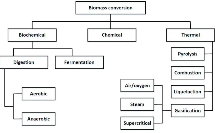
Biomass can be used directly to release energy in the form of heat or electricity, or may be converted to another form, such as liquid (ethanol, biodiesel, methanol, vegetable oil, and pyrolysis oil), gas [biogas (CH4, CO2), producer gas (CO, H2, CH4, CO2, H2), syngas(CO, H2), substitute natural gas (CH4)] or solid (charcoal, torrefied biomass) [4]. Conversion of biomass into useful forms of energy or chemical products is categorized into three groups (Figure2.3).
Figure 2.3 Methods of biomass conversion to fuel, gases and chemicals
2.2.1 Chemical conversion
The two principal methods to produce chemicals from biomass are based on sugar and syngas. The final products of sugar based methods include xylose, fructose, glucose, arabinose, lactose, su-crose, and starch [4]. Syngas is a mixture of predominantly H2and CO with trace amounts of CH4, H2O and CO2. Syngas is a building block to produce numerous chemicals including hydrogen,
methanol, glycerol (C3), fumaric acid (C4), xylitol (C5), glucaric acid (C6), and gallic acid (Ar) [5]. Each of these components can be an intermediary to produce a large number of chemicals, which can be used in transportation, textile and food industries, the environment, communications, health, housing, and recreation [5]. Although chemical conversion methods result in a value added product, in most cases they cannot use biomass directly and the first step is to convert biomass to sugar or syngas via another process.
2.2.2 Biochemical conversion
In this process biomass components are decomposed to smaller molecules by bacteria, microor-ganisms and enzymes. Digestion (anaerobic or aerobic) and fermentation are the most popular biochemical technologies. Anaerobic digestion is a biological process, which stabilizes organic materials in the absence of oxygen and transforms it into solid residue (bio-fertilizer) and biogas (mostly CH4and CO2). The bacteria supply the oxygen from the biomass rather than the air. Aer-obic digestion uses different types of bacteria that access oxygen from the air, producing carbon dioxide, heat, and a solid residue [6]. The fermentation process is to convert the plant’s glucose (or carbohydrate) to an alcohol or acid by yeast or bacteria. In fermentation the bacteria touch only the sugar based materials and the other components in the biomass (e.g., lignin) are left unchanged. Therefore, it is more economical to use a biomass with high sugar content (e.g., sugarcane, corn or sweet potatoes) for fermentation. Biochemical conversion of biomass is inexpensive but the conversion rate is much slower compared to thermal and chemical processes [6].
2.2.3 Thermal conversion
Thermal conversion is one of the most important processes to convert biomass to energy. In all thermal processes heat is the dominant mechanism to convert biomass. Thermal processes are classified into three categories based on the oxygen availability as combustion, pyrolysis and gasification.
Combustion
Combustion is the thermal degradation of hydrocarbons (CxHyOz) in the excess air atmosphere.
Water vapor, carbon dioxide, and heat are the main products of combustion (Eq. 2.1).
aCxHyOz+ bO2−−→ cCO2+ dH2O + Q (2.1) The produced energy can be used to generate electricity or mechanical movement and also for heating purposes. Combustion happens at 700<T(◦C)<1400 [7]. In air combustion, the separation of CO2from the un-reacted O2and N2is difficult. Therefore, the CO2is released to the atmosphere without separation. Furthermore, combustion in air creates several forms of nitrogen oxide-NOx,
which are not environmentally friendly.
Pyrolysis
Pyrolysis is thermal decomposition of substances by heating them at high temperature and in an oxygen free atmosphere. Pyrolysis occurs at a temperature range of 380-530◦C [7]. As a result, it takes part in all other thermal conversion processes. There is some content of oxygen in biomass or other solid fuels and, therefore, achieving a complete pyrolysis is impossible. This process can be represented by the following general reaction:
Biomass + Q −−→ Char + Gases + Vapour or Liquid (2.2) The produced gases are mostly CO, H2, CO2, CH4, and H2O and liquid products are water, tar and bio-oil. Tar is a viscous and sticky liquid, which contains heavy organic and inorganic molecules. Tar causes many challenges for downstream facilities, like filters, compressors, etc. Up to 200◦C only water is driven off. Between 200 to 280◦C carbon dioxide, acetic acid and water are reduced. The main step of pyrolysis, which takes place between 280 to 500◦C, produces large quantities of tar and gases, including carbon dioxide. The composition of the pyrolysis products depends on the fuel type, temperature, and heating rate. Increasing the temperature beyond 900◦C
decomposes the tar and increases the gas yield [8]. Pyrolysis is an endothermic process and also 20-40 % of the carbon remains as char [8].
Gasification
Gasification is a flexible, reliable, and clean energy technology that can turn a variety of low-value feed stocks into high-low-value products. The product of gasification is mostly a gas rich in H2 and CO, called syngas. Tarry components also might form during gasification but their formation is low due to the presence of oxygen and/or steam and the high temperature of gasification [9]. The H2/CO ratio and the impurity level of the syngas determine its application. Syngas is a building block in the chemical industry and only a small portion of syngas comes from biomass gasification. The largest part of the syngas is used to synthesize NH3 (53 %), which is used in the fertilizer industry. H2 production is the second consumption of syngas by 23 %. The production of liquid fuels via Fisher-Tropsch and methanol comprises about 20 % of syngas consumption and only 4 % of the syngas is used for electricity generation (Figure 2.4). However, it is expected that the syngas applications will shift from the production of ammonia to the synthesis of liquid fuels by 2040 with as much as 40 % of the market [9].
Figure 2.4 World syngas market in 2004 [10]
If power generation is the only desired application, combustion seems preferable and more economical compared to gasification, especially in small to medium-scale plants. However, gasi-fication is the primary step to produce high value liquid fuels, which makes it more favourable compared to combustion. The formation of NOx in gasification is much less due to the lack of
oxygen. Furthermore, the sulfur appears in the form of H2S during gasification, which is easier to separate from the effluent gas compared to SO2 formation in combustion. Air (or oxygen), steam, plasma and supercritical are the main gasification technologies.
Air or oxygen gasification
The oxygen required for air gasification is just enough to supply the energy for the entire reac-tion. In other words, by introducing oxygen to the reactor, the exothermic reactions (Eq. 2.3 and
Eq. 2.4) take place and supply the energy for the endothermic reactions [11].
C + 0 · 5 O2−−→ CO + 111 (kJ/mol) (2.3)
C + O2−−→ CO2+ 394 (kJ/mol) (2.4)
Reaction 2.4 consumes twice as much O2 as the Reaction 2.3. Therefore, in an oxygen deficient atmosphere, the first reaction is more likely to take place. The ratio of the oxygen required to gasify the biomass compared to the oxygen required for complete combustion is known as the equivalent ratio (ER):
ER= Required O2 f or gasi f ication
Required O2 f or complete combustion (2.5) The ER is normally in the range of 0.2-0.3 [4]. The oxygen content of fuel can affect the ER. The oxygen in biomass (typically 40-60 wt %) is removed by dehydration or decarboxylation (Eq. 2.6and 2.7) and is not available for gasification.
CxHyOz−−→ CxHy−2z+ qH2O (2.6)
CxHyOz−−→ Cx−q/2Hy+ qC2O (2.7)
The other reaction which is endothermic and occurs during gasification, is the Boudouard reac-tion (Eq. 2.8):
C + CO2−−→ 2 CO−162 (kJ/mol) (2.8)
The Boudouard reaction plays an important role in the final gas composition, especially CO and CO2. Air gasification produces a low heating value of gas (4-6 MJ/m3) and a high nitrogen content of 45-55 %. A gas with a low nitrogen content and a high heating value (12 MJ/m3) is produced
with pure oxygen as the gasification agent (the heating value of methane is 40 MJ/m3) [12].
Steam gasification
The most important reactions during steam gasification are as follows:
C + H2O −−→ CO + H2−161 (kJ/mol) (2.9)
CO + H2O −−→ CO2+ H2−42 (kJ/mol) (2.10) Steam gasification is endothermic. Therefore, an external source of energy is required to derive the reactions. The required energy can be provided indirectly by subjecting oxygen to the reactor and deriving exothermic reactions. In this case the ER is more than the air gasification. The H2O/C molar ratio is a crucial operational parameter during steam gasification. Introducing more steam to the reactor (increasing H2O/C ratio) increases the H2yield and, consequently H2/CO ratio due to the water-gas shift reaction (Eq. 2.10). The H2O/C molar ratio depends on the gasification product application, and generally is in the range of 1-3 [8]. The formation of tar during steam gasification is less due to the hydrothermal decomposition of heavy molecules with water.
Supercritical steam gasification
Supercritical gasification is a relatively new technology which uses supercritical water (T > Tc=374oC, P > Pc=220.64 bar) as the gasification agent. Under supercritical conditions the reaction
of organic substances with water is very fast and converts biomass/waste into a medium heating value gas. The syngas from supercritical gasification is rich in hydrogen and is not diluted by nitrogen. More importantly, the produced gas is already at high pressure and can be integrated directly to the Fischer-Tropsch process, which operates at high pressure [13, 14].
Plasma gasification
In plasma gasification, the biomass or solid waste is decomposed to gases and slag using a plasma torch. An inert gas (usually steam) becomes superheated by passing through an electric arc. The electric arc is created by applying a strong electric current under high voltages through two electrodes. The torch temperature ranges from 2200◦C to 13 900◦C and can convert any type of waste to gas and solid residue. The produced gas from plasma gasification is cleaner and has no heavy components compared to conventional gasification [15, 16].
2.3 Syngas cleaning
Syngas is mainly produced by partial oxidation or steam reforming of natural gas (Eq. 2.11, 2.12). A small portion of the syngas comes from gasification of coal or biomass. The syngas coming from gasification, especially biomass (referred to as bio-syngas), is highly dirty and has to be cleaned before being sent to other units.
CH4+12O2−−→ CO + 2 H2 (2.11)
CH4+ H2O −−→ CO + 3 H2 (2.12)
The most common impurities of bio-syngas are the following: particulate matter, tar and con-densable hydrocarbons, sulfur and CO2 and N2. Alkali metals and chlorine are also the other impurities of syngas. However, their quantity is very low, which can be tolerated by most of the syngas applications.
Particulates
Elutriated particles from the gasifier range between 1µm to over 100 µm [17] are basically ash and un-reacted solid residue. They cause fouling, corrosion, and erosion of the downstream facilities. Therefore, many syngas applications, even combustion processes, require more than 99 % particulate removal [18]. Particulates can be removed by three main technologies: internal
separation, filtering and electrostatic precipitation [19]. The internal separation approach uses the mass difference between particulate and gas. Cyclones and dust agglomerates are the most common devices in this category. Filtering occurs when a gas stream passes around fibers or through a porous solid. Electrostatic separators (ESP) remove the solids and fine particles by applying a strong electric field. The gas stream flows through many wires. A negative voltage of several thousand volts is applied to the wire and the particles became ionized. The charged particles flow with the gas stream through a stack of large flat metal plates, which are connected to a high positive voltage source. The particles stick to the plates and form a layer. The electrostatic separators are very effective in removing particulate matter from gas streams [20].
Tar
Tar is considered the main challenge of the gasification process because it can block filters and lines and damage the downstream processes. The tar content of syngas depends on the operating conditions, gasifier type, and feed. Increasing temperature decreases tar formation [19, 21, 22] but increasing temperature beyond a certain point may cause clogging and the sintering of particles in the gasifier. Ciferno and Marano [23] reported that the tar yield is 10-20 % in an up-draft gasifier where the carrier gas and solids are counter-current while in a down-draft gasifier with a co-current flow of gas and solid, the tar yield is as low as 1 %. The syngas produced from biomass has a higher tar concentration compared to coal or peat gasification [24]. Removing all tar and heavy components from syngas may be expensive and not applicable. However, a practical way is to eliminate a sufficient amount of tar until the dew point of the syngas drops below the minimum temperature experienced by the gas stream [25].
Thermal cracking, catalytic cracking, and physical separations are the main techniques to re-move tar from the produced gas [18]. Non-physical methods eliminate tar by increasing the tar decomposition rate. Usually these techniques are applied in a secondary vessel (post-gasifier). However, thermal and catalytic cracking can be applied in-situ with gasification as well. In thermal cracking, large organic compounds are broken down into smaller non-condensable gases at high
temperatures (1100-1300◦C). The higher the temperature is, the less residence time is required [26, 27]. Although thermal cracking seems to be simple in principle, implementing a high temper-ature gasifier is difficult and expensive. In some cases it is even more economical to have separate tar cleanup equipment and a low temperature gasifier rather than a high temperature gasifier [28– 30].
In catalytic cracking, the catalyst increases the tar cracking rate by decreasing the activation energy. Catalytic cracking, unlike thermal cracking, does not suffer from high temperatures. How-ever, catalyst deactivation, especially during the in-situ process, is problematic. Agglomeration, attrition, poisoning with sulfur, and coke formation are the main deactivation mechanisms. Dif-ferent materials have been reported to have a catalytic effect for the tar decomposition reaction, including nickel, iron, alkali-based metals, activated alumina, FCC, char and less expensive ma-terials, like calcined dolomite, limestone, calcined rocks, olivine and clay minerals [31–35]. The literature in this domain is extensive with a prominent review paper from Woolcock et al. [18].
At temperatures lower than 450◦C tar starts to condense and forms heavy droplets, which re-semble the particulate matter [36]. Therefore, they can be removed by the techniques presented for the removal of particulate.
Sulfur and CO2
Sulfur compounds usually appear in the form of H2S and COS during gasification. The sulfur content of biomass is significantly less than coal (0.5 g/kg compared to 50 g/kg) [37]. Sulfur causes the corrosion of metal surfaces and also contaminates the metal catalysts in post processing facilities. Furthermore, if the syngas is burned, the sulfur compounds convert to SO2, which can produce acid gases. Neglecting the green house gas effect of the CO2, it is considered as a diluent rather than an impurity for the post-processing of syngas. In other words CO2 does not negatively impact the downstream catalytic processes.
Adsorption and absorption are the two main processes to remove H2S and CO2. The adsorption can be applied at high and low temperatures. The high temperature process can be integrated
with the gasification. The adsorbent removes the impurities from the syngas in one vessel and is transferred to another vessel for regeneration. CaO, activated carbon, metal-based adsorber and zeolite are normally used as adsorbers.
Chemical absorption with amine solutions are the most commonly used CO2-H2S (acid gases) removal technologies, which rely on the reactions of the acid gas with the solvent to form weakly bonded compounds. The absorbed acid gas can be released by applying heat and the solvent is regenerated [38]. Physical solvent absorption may be competitive with amine processes when the feed gas is available at high pressure (generally P>20 bar) [39]. The Selexol and Rectisol processes are the leading physical absorption technologies to treat feed gas with a high CO2 concentration [40]. In the Selexol process polyethylene glycol di-methyl ether is used as a solvent, which is able to remove CO2, H2S and water simultaneously. The solubility of H2S in most organic solvents is higher than CO2, which helps to remove it completely [41]. The solvent can be regenerated by decreasing the pressure in a series of vessels.
Nitrogen
Nitrogen is considered as a diluent and contamination of syngas. Air as the oxygen source of gasification contains 78 % N2. Therefore, the syngas from air gasification has a considerable amount of nitrogen (30-50 %). This will affect the size and, consequently, the equipment cost of the processes after the gasifier. Also, the presence of nitrogen in the gasifier forms nitrogen compounds, such as NOx, NH3 and HCN. NOx contributes to global warming and affects the
environment by producing acid rain. Gas turbines usually demand a syngas with an ammonia concentration less than 50 ppm to control the NOx emissions [42]. Furthermore, a syngas with
an ammonia concentration of 0.05 ppm can deactivate the catalysts used to upgrade syngas [42]. There are two main approaches to remove nitrogen from biomass: to avoid direct contact of air and fuel; and to separate nitrogen from the syngas after gasification. In the latter approach nitrogen has already entered in the gasifier, which may form toxic nitrogen compounds. Therefore, the former technology is of more interest. The direct contact of nitrogen and fuel can be avoided by either
feeding pure oxygen (generated from air separation units-ASU) instead of air or using a chemical looping system for gasification.
2.4 Air separation units (ASU)
Cryogenic and non-cryogenic systems are the main air separation methods. Cryogenic systems are preferable whenever a large capacity with high purity separation is required. Non-cryogenic systems, including adsorption and membrane technologies, are generally for lower product purities.
2.4.1 Cryogenic systems
In cryogenic methods, air is compressed and cooled first. Next the water and carbon dioxide are removed by molecular sieve adsorbers. The air is then cooled by exchanging heat with the cold streams of the gaseous products and afterward liquefied by a refrigeration process. The liquefied air is sent to a set of distillation columns and separated into oxygen, nitrogen and argon. The cryogenic technology consumes a lot of power, specifically in the refrigeration step (0.28-0.3 kWh/Nm3[43, 44]). Therefore, it is not economical unless a large capacity of separation is required.
2.4.2 Adsorption systems
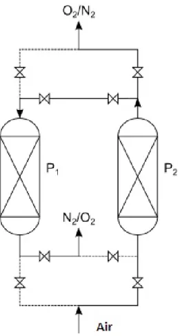
Pressure swing adsorption (PSA) and vacuum pressure swing adsorption (VPSA) are the main adsorption technologies to separate oxygen from air. The air is switched periodically between two beds packed with a zeolite molecular sieve. Nitrogen is adsorbed more strongly by zeolite compared to oxygen molecules. Therefore, the outlet stream is concentrated in oxygen. When the adsorbent becomes saturated with nitrogen, the air is switched to the second bed. To increase the adsorption rate, the bed is pressurized. In the case of PSA, the saturated bed is de-pressurized to atmospheric pressure while for VPSA the bed is subjected to vacuum to provide an additional driving force for regeneration. A small portion of produced oxygen is used to flush the adsorbed gas, preparing the bed for another cycle (Figure 2.5).
Figure 2.5 Pressure swing adsorption, bed 1 in regeneration, bed 2 in process, P2>P1
Each bed is saturated in the order of 10 s [44], and every time the composition of the gas feed changes, it takes on the order of hours to reach steady state conditions [45]. Therefore, adsorption systems compared to cryogenic processes are not flexible. Membrane technology is also another air separation method, which has received substantial attention in recent years. The permeability of oxygen in some materials like polysulphone, is five times more than nitrogen [43]. This property is used to separate two gases. Membrane processes can deliver oxygen with low-medium purity levels; however, clogging is their main challenge.
2.4.3 Chemical looping process
A chemical looping system is a process to supply the required oxygen for oxidation (or partial oxidation) and contains two vessels: oxidation and reduction. A metallic particle (Me) circulates
between two vessels and serves as an oxygen transporter. In an oxidation reactor, which is usually called air reactor, the metallic particles (Me) adsorb oxygen from air at high temperature (∼800◦C) and is converted to metal oxide (MeO). MeO is transferred to the reduction vessel, which is usually called fuel reactor. In a reduction reactor, MeO loses the oxygen that is in contact with a reducing agent. The reducing agent can be a gaseous fuel (CH4), solid (coal, biomass) or even an inert media, like N2. The fuel reactor is also working at high temperature (∼800◦C). The reduced particles (Me) are transferred to the air reactor for regeneration. Using this configuration, oxygen is supplied without direct contact of fuel with air. Consequently, the outlet stream from the fuel reactor is free of nitrogen.
The oxides of Ni, Cu, Cd, Mn, and Fe, which have the ability to be reduced and oxidized periodically, have been studied as metal oxides for chemical looping systems. Considering the weight of metal oxide in its fully oxidized and fully reduced forms as mOxi and mRed, the oxygen
transport capacity (R) of a metal oxide is defined as follows:
R= mOxi− mRed
mOxi (2.13)
A higher oxygen carrying capacity results in a lower solid circulation rate. The oxidation-reduction rates are also very important parameters in designing a chemical looping system. A metal oxide with a high oxidation-reduction rate requires less residence time in the oxidizer-reducer to reach a certain conversion, which results in a smaller reactor. The metal oxide is subjected to high mechanical stress due to the intense solid-solid contact. Therefore, to improve its lifetime and durability, it is dispersed on a support (e.g., Al2O3, SiO2). The metal oxide dispersed on the support is referred to as the oxygen carrier. The metal oxide should have a proper heat capacity, as besides carrying oxygen, it can serve as a heat transfer media. Therefore, a metal oxide with a high heat capacity can moderate the heat effect caused by endothermic or exothermic reactions to a greater extent [46]. Cost, resistance to contamination, melting point, physical durability, and environmental impacts are other factors that have to be considered in the selection of metal oxide.
2.5 Preparation of the oxygen carrier
2.5.1 Mechanical mixing
Mechanical mixing is the simplest and less expensive method to prepare a supported oxygen carrier. This process involves mechanically mixing of metal oxide with a support. A binder can be used to reinforce the metal oxide-support bond. Calcination and processing to the desired size are the next steps in mechanical mixing. Calcination persuades interactions between the support and metal and results in an oxygen carrier with a higher mechanical strength [46]. The homogeneity of the oxygen carrier prepared by mechanical mixing is poor, giving the oxygen carrier a metal oxide rich phase and a support rich phase. Therefore, for low melting point metal oxides (e.g., copper), mechanical mixing is not proposed to prepare the oxygen carrier [47].
2.5.2 Wet impregnation
The support is soaked in a metal nitrate solution and after mixing for a certain time, the solution is filtered and dried. Then the powder is calcined in air to decompose the nitrates into non-soluble oxides. The weight difference between the impregnated and fresh support indicates the oxide per-centage in the support. This method can be repeated several times to achieve the desire oxide percentage. A part of the active phase forms on the outer layer, which has a weak bond with the support. This layer is attired after initial cycles and therefore, the oxygen carrier does not show the expected performance.
2.5.3 Incipient wetness impregnation
The difference between incipient wetness impregnation (also referred as dry impregnation) and wet impregnation is the volume of metal nitrate solution used. The amount of the metal nitrate solution is equal to the total pore volume of the support. Therefore, no nitrate solution is wasted during preparation. Like wet impregnation, drying and calcination are the next steps in preparation. Adding just enough solution to fill the total pore volume causes poor homogeneity in the final
product.
2.5.4 Co-precipitation
The metal and support sources, which are in liquid form, are mixed together. To precipitate the metal and support, a precipitating agent (e.g., alcohol) is added to the mixture. The precipitated powders are filtered and dried to remove the water. Finally the dried powders are calcined in air at high temperature to remove the impurities. The pH of the solution controls the precipitation rate of the support and metal sources [47]. Co-precipitation results in a more homogeneous mixture compared to impregnation.
2.5.5 Freeze granulation
In freeze granulation, the metal oxide and support are mixed with distilled water. To improve the homogeneity, polyacrylic acid can be added to the mixture as a dispersant. A fine powder slurry is then obtained by grounding the mixture in a milling instrument. Finally, the mixture is dried in a freeze dryer and is calcined at high temperature in air. The oxygen carrier prepared by freeze granulation is very homogenized in size and shape. However, like mechanical mixing, the metal oxide is not well dispersed on the support phase [48]. The metal oxide (MeO) and support (e.g., γ -Al2O3) after calcination can form a spinel structure (MeAl2O4):
MeO+ Al2O3
calcination
−−−−−−→ MeAl2O4 (2.14)
The spinel structure traps the metal oxide and therefore the oxygen of the oxide is no longer avail-able for the fuel, which affects the performance of the oxygen carrier [49]. To avoid this effect, the spinel structure can be used itself as a support. Chemical looping systems can be used in combus-tion, H2production, gasification, and any other process that requires oxygen.
2.6 Chemical looping combustion-CLC
CLC is the most common application of chemical looping technology. Basically, chemical looping technology has been proposed first to produce pure carbon dioxide from carbon monoxide by copper oxides [50]. CLC of gaseous fuels (Figure 2.6) (e.g., methane or syngas) for power generation have been extensively explored during the last two decades [51, 52]. The possibility of using solid fuels (e.g., biomass or coal) in CLC has received more attention in the past 10 years [53–56]. The general reaction in the reduction reactor is as follows:
Reduction side: MeO + Solid or gaseous fuel −−→ Me + CO2+ H2O (2.15) H2O is separated from CO2 by condensation and CO2 is sent for sequestration. Reaction 2.15 can be endothermic or exothermic depending on the type of oxygen carrier [46]. The general reaction in the oxidizer is as follow:
Oxidiation side: Me + Air −−→ MeO + O2+ N2 (2.16) Reaction 2.16 is always exothermic and can support some of the energy for the reduction side (if necessary) through sensible heat carried by the oxygen carrier.
Figure 2.6 Chemical looping combustion of gaseous fuels
The most common configuration of the CLC of gaseous fuels is based on a low velocity bub-bling fluidized bed as the reducer and a high velocity riser as the oxidizer [57]. In chemical looping combustion of solid fuels the solid-solid reaction rate between oxygen carrier and solid fuel is low. There are two approaches to this issue: in-situ gasification chemical looping combustion (iG-CLC) process; and chemical looping oxygen uncoupling (CLOU) process. In iG-CLC the solid fuel is first gasified with CO2and H2O to CO and H2. The released gas then reacts with the oxygen carrier and produces CO2and steam (Figure 2.7) [54]. The first step, which is the gasification of solids, is slow, thus a high solid residence time should be applied to reach a high conversion [57].
Figure 2.7 in situ gasification-chemical looping combustion process
In the CLOU process, the metal oxide is subjected to a lean oxygen atmosphere and releases (pumps) oxygen to the system. The oxygen reacts directly with solid fuels and volatile gases (Figure 2.8).
Figure 2.8 Chemical looping oxygen uncoupling process [57]
CLOU does not require the gasification step. However, only a limited number of oxygen carri-ers are able to release oxygen at high temperatures. CuO/Cu2O, Mn2O3/Mn3O4 and Co3O4/CoO
systems have been reported as proper oxygen carriers for CLOU with the oxygen transport capacity of 0.1, 0.03 and 0.066 respectively [58].
2 CuO ←→ Cu2O +12O2(g) ∆H850= 263.2 kJ/molO2 (2.17)
3 Mn2O3←→ 2 Mn3O4+12O2(g) ∆H850= 193.9 kJ/molO2 (2.18)
Co3O4←→ 3 CoO +12O2(g) ∆H850= 408.2 kJ/molO2 (2.19)
Copper is the most studied oxygen carrier for the CLOU process. The agglomeration possibility of copper is less in CLOU compared to the normal CLC process because copper presents as CuO and Cu2O and it never reduced completely to pure copper. The melting point of CuO and Cu2O are 1446 and 1235◦C respectively, which are higher than pure copper (1085◦C). A 1.5 KWth
ICB-CSIC unit working with copper as the oxygen carrier and bituminous Colombian coal as the fuel is the only proof of concept for CLOU technology, which was developed by Adanez-Rubio et al. [59]. They have reported a 97 % conversion of char at 940◦C with no un-burnt volatile matter at the reactor outlet. Cobalt has a moderate oxygen transport capacity (6.6 %) but it has been researched less due to the high cost and high amount of required energy for decomposition (Equation 2.19). Manganese is also less attractive due to its low oxygen transport capacity.
2.7 Chemical looping process for H2production
Chemical looping water splitting (CLWS) is a new technology to produce pure H2 using the chemical looping concept. The CLWS is exactly like CLC with the difference that in the oxidation reactor steam is used to oxidize (or partially oxidize) the metal oxide. Therefore, water is hydrolysis to H2and O2and the hydrogen is separated by condensation from water in the outlet stream (Figure 2.9).
T able 2.1 Operating CLC system Name Capacity Fuel T em perature ( oC ) Oxygen carrier Reference CLC of gaseous fuels The Chalmers Uni v ersity 10-kW th Methane 950 N iO / N iAl 2 O4 L yngfelt and Thunman[60] (CSIC) System 10-kW th 75 % N2 + 25 % C H4 700-800 C uO / γ -Al 2 O3 de Die go et al. [61] VUT CLC System 120-kW th Natural g as 850-940 N iO / N iAl 2 O4 50 % + K olbitsch et al. [62] Proll at al. [63] N iO / (N iAl 2 O4 -M gAl 2 O4 ) 50 % KIER CLC System 50-kW th C H4 869-890 N iO / Ben toni te Ryu et al. [64] C ox Oy / C oAl 2 O4 CLC of solid fuels Modified Chalmers Uni v ersity 10-kW th South African coal 950 Ilmenite Ber guerand and L yngfelt [65] Petroleum cok e Ber guerand and L yngfelt[66] Southeast Uni v ersity 10-kW th Coal 960-970 N iO / Al 2 O3 Shen et al. [67, 68] Biomass F e2 O3 Shen et al. [69] ICB-CSIC 1.5-kW th Bituminous coal 900-960 C uO Adanez-Rubio et al. [59]
Figure 2.9 Chemical looping water splitting for hydrogen production [70]
The metal oxide used for water splitting should be able to use water as the oxidant, which makes it different from conventional metal oxides for CLC. FeO/Fe3O4 is the most studied metal oxide for hydrogen production [70] with the governing equations as follows:
Reduction side: Fe3O4+ CH4−−→ 2 FeO + CO2+ 2 H2O ∆H873K = 325 kJ/mol (2.20)
Oxidation side: 3 FeO + H2O −−→ Fe3O4+ H2 ∆H873K = −58 kJ/mol (2.21)
Chiesa and Lozza [71] have shown that water is not able to completely regenerate the metal oxide. Therefore, they proposed a complete oxidation of metal oxides with air in a third reactor before transferring to the reduction reactor.
2.8 Chemical looping Gasification-CLG
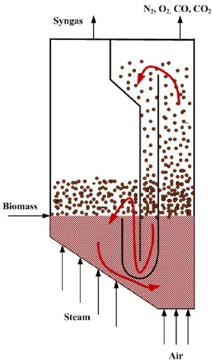
Despite all the advantages of gasification over combustion, including the production of liquid fuels and synthetic materials, the application of chemical looping technology in gasification has not been explored extensively in the literature. Hofbauer et al. [72, 73] are among the few researchers who applied chemical looping technology to produce syngas from the gasification of organic ma-terial. Basically, they used a chemical looping system working with olivine to supply the required energy for steam gasification. Steam gasification of biomass (reaction 2.9) and water-gas shift re-actions (reaction 2.10) are the governing rere-actions that take place during steam gasification. A part of the un-reacted biomass (char) is transferred to a combustion reactor where it is burned with air. Olivine particles circulate between combustion and gasification sections and transfer produced heat from combustor to gasifier (Figure 2.10).
Figure 2.10 The Fast Internally Circulating Fluidized Bed (FICFB) gasification system, the arrows correspond to the solid circulation between two sections
This process was later commercialized by AE&E, Repotec and Ortner Angenbau to produce high purity syngas. The syngas produced using this technology is concentrated in hydrogen and the H2/CO ratio is >4 [74], which is not suitable for liquid fuel synthesis. Furthermore, the CO2 from the combustion of un-burnt char in the combustor is sent into the atmosphere. Olivine as a bed material serves as a heat carrier rather than an oxygen carrier. Lancee et al. [75] used the same concept and olivine as bed material for biomass gasification. Besides the heat carriage of olivine, they reported that the iron in the olivine has a catalytic effect on tar cracking. Also, iron
is capable of releasing oxygen to the gasifier, which compensates the endothermicity of the steam gasification. Calcium oxide can be also used as a circulating material instead of olivine. Using calcium oxide not only provides the required energy, it serves to remove the CO2and H2S from the gasifier (Reactions 2.22 and 2.23) and a syngas with high purity [76].
CaO + CO2←→ CaCO3 (2.22)
CaO + H2S −−→ CaS + H2O (2.23)
2.9 Summary
Solid fuels, especially biomass compared to fossil fuels, are more abundant and inexpensive, which should encourage us to develop a process to utilize them in the industry. Gasification as a tool to convert invaluable solid fuels to syngas has been proven to be more beneficial over combustion if the liquid products were interesting. Using air as a gasifying agent dilutes the produced syngas and for post-processing units the separation of nitrogen is required. The chemical looping concept is a promising technology to supply oxygen indirectly. There is a chance to integrate gasification with the chemical looping concept to produce a high purity syngas free of nitrogen. Chemical looping has been extensively studied for the combustion of gaseous and solid fuels as well as H2 production. These applications require high amounts of oxygen for complete oxidation. On the other hand chemical looping is not very effective in terms of oxygen supplier. Therefore, it might be asked that why the chemical looping concept has not been used extensively in the literature for gasification, which requires less oxygen (20-30 % of the oxygen required for combustion).
The oxygen uncoupling materials which are able to release oxygen at high temperature have been used in combustion of solid fuel. However, their application for the gasification of solid fuels has never been tried. The proposed biomass gasification process by Hofbauer et al. [72] is very interesting in terms of self producing energy process. However, the H2/CO ratio is greater than 4 which is not suitable for post syngas processing (Fischer-Tropsch or methanol production).
Keeping the same reactor configuration (as Hofbauer et al. [72]) in this thesis, we have tried to replace the olivine with an uncoupling oxygen carrier. It is predicted that the released oxygen in the gasifier not only will provide required heat for the steam gasification, it will increase the CO yield and consequently lower the H2/CO ratio.
CHAPTER: 3
COHERENCE OF THE ARTICLES
Chapters 4 to 6 are the main body of this thesis and include, in general, the oxygen carrier selection, the effect of the oxygen carrier on the biomass gasification, and the economic analysis which answer the specific objectives of this research. More specifically, they cover the following topics:
– Chapter 4 includes the first article entitled “TGA and kinetic modeling of Co, Mn and Cu oxides for Chemical Looping Gasification (CLG)”. The oxygen carriers were prepared via incipient wetness impregnation. The oxygen transport capacity, the temperature in which the oxygen carrier reacts with oxygen and releases oxygen, and the oxidation-reduction rates of oxygen carriers were compared by the thermo-gravimetric analysis. The total surface area and XRD pattern of the fresh and used oxygen carriers were measured to compare the ther-mal strength. Finally, a new model was derived to predict the reduction-oxidation rates. The new model takes into account the effect of the reverse reaction in the oxygen release from the oxygen carrier;
– In Chapter 5 the second article, “Transient modeling of biomass steam gasification with Co3O4” was presented. After the selection of the oxygen carrier, its performance in the presence of biomass was tested in a 7.8 cm fluidized bed reactor. Tar and sticky liquids form during biomass gasification which can deactivate the oxygen carrier and affect its perfor-mance. In addition to the effect of the oxygen carrier, the effects of steam and temperature on the product gas composition have been measured. A two phase model was proposed for the gas phase hydrodynamic in the dense bed region. The hydrodynamic model was verified by performing a residence time distribution test of argon. Using the proposed hydrodynamic
model and the oxygen desorption rate from the first article together with the reaction rate expression from the literature, the CO, CH4, H2and CO2composition was calculated along the reactor and the results were compared with the experimental data;
– Chapter 6 includes the third article entitled “Design and economical analysis of a chemical looping gasification process”. Using the kinetic data obtained in the first and second paper, a chemical looping gasifier to treat 86.4 t/d, including a bubbling fluidized bed as the gasifier and a high velocity riser as the oxidizer was designed. The objectives of the preliminary design were to calculate the diameter and height of the gasifier and oxidizer. The height of the gasifier was calculated based on the required steam residence time to reach 90 % biomass conversion. Also, the oxidizer height was calculated based on the required residence time of the oxygen carrier for regeneration. Furthermore, the possibility of an autothermal gasifica-tion using a chemical looping system has been studied. Finally, an economical analysis has been performed to compare the feasibility of a chemical looping gasifier and a conventional gasification process.
![Figure 2.4 World syngas market in 2004 [10]](https://thumb-eu.123doks.com/thumbv2/123doknet/2322535.29402/29.918.167.780.158.547/figure-world-syngas-market-in.webp)
![Figure 2.8 Chemical looping oxygen uncoupling process [57]](https://thumb-eu.123doks.com/thumbv2/123doknet/2322535.29402/43.918.158.741.616.921/figure-chemical-looping-oxygen-uncoupling-process.webp)