Science Arts & Métiers (SAM)
is an open access repository that collects the work of Arts et Métiers Institute of
Technology researchers and makes it freely available over the web where possible.
This is an author-deposited version published in: https://sam.ensam.eu Handle ID: .http://hdl.handle.net/10985/6738
To cite this version :
Xavier KESTELYN, Eric SEMAIL - A Vectorial Approach for Generation of Optimal Current References for Multiphase Permanent-Magnet Synchronous Machines in Real Time - IEEE Transactions on Industrial Electronics p.5057-5065 - 2011
Any correspondence concerning this service should be sent to the repository Administrator : archiveouverte@ensam.eu
A Vectorial Approach for Generation of Optimal Current References
for Multiphase Permanent Magnet Synchronous Machines in Real-time
Post IEMDC09 paper [22]
Abstract- This paper deals with the generation of optimalcurrent references for Multiphase Permanent Magnet Synchronous Machines in normal or fault mode (open-circuited phases). Current references are computed in order to keep a constant torque while minimizing instantaneous Joule losses. In comparison with commonly used scalar methods, a vectorial approach makes it possible to reduce the number of computations in order to generate optimal current references, in real-time. In addition to this, since current references are expressed in terms of physical parameters of the machine, this approach can be used to evaluate the influence of the machine parameters over the control performances. Finally, experimental results of a surface mounted permanent magnet five-phase synchronous machine are provided in order to demonstrate the proposed strategy.
I. INTRODUCTION
For some specific applications, standard three-phase variable-speed drives are replaced by multiphase drives. The main reasons for this choice are a high level of power and fault tolerance capabilities. Concerning the latter point, multi-phase drives offer, due to their inherent additional degrees of freedom, a good solution in terms of fault tolerance [1],[2]. For example, a star-connected n-phase machine can run with up to (n-3) phases in fault-condition with no additional devices.
Among the most current applications of multiphase drives, one can name: electric ship propulsion, locomotive traction, electric and hybrid electric vehicles, ‘moreelectric’ aircraft, and high power industrial applications [1]-[5]. Due to their high torque to volume ratio and the low level of torque ripples, Multiphase Surface Mounted Permanent Magnet Synchronous Machines are used in naval propulsion [5]. As examples, one can cite submarines Scorpene from DCNs-AREVA-Jeumont (based on a 13-phase PM motor) or Permasyn from Siemens (based on a 12-phase PM motor).
Among many types of faults which can occur, the open-circuit faults are the most commonly found. These faults are mainly due to power device failures. In these cases, the currents in the healthy phases must be modified to reduce the impact of the fault on the torque quality. Several post-fault strategies may be applied. In most of these cases the objective is to keep a constant torque even with open-circuited phases. The limiting factor is either the thermal state of the machine or the maximum current per inverter leg, which are respectively linked to the level of Joule losses and the peak phase current. Among the post-fault strategies, three sets of methods can be discussed here.
In the first set, the aim is to control currents in the remaining phases in order to keep balanced currents (i.e. with identical shape and amplitude). The method consists of imposing specific current waveforms to the remaining phases and finding
the best phase displacement for each current in order to obtain a constant torque [6]-[11]. With this strategy, each phase generates the same Joule losses and, for some particular phase arrangements, the thermal behaviour of the machine is controlled. Moreover, the peak phase current is also controlled. Calculations are then reduced to the resolution of a system consisting of a number of equations equal to the number of unknowns (the phase displacements). Even if this type of strategy is well suited for machines with sinusoidal winding distribution and imposed sinusoidal currents, calculations become rapidly complex when several harmonics of winding distribution have to be taken into account. Reference [9] shows that the harmonics of the winding distribution can lead to a 4th
order harmonic torque even if sinusoidal currents are imposed. Moreover, when this method has been adapted to currents with a third harmonic component, torque pulsations have been observed [11]. Finally, it must be remarked that even if Joule losses are the same in each of the healthy phases, the temperature is not the same in each winding since it depends on the neighbouring phases, which can be open-circuited or not.
In the second set of existing strategies, phase currents are unbalanced but global Joule losses (i.e. generated by all connected phases) are minimized [12]-[14]. This approach leads to find the minimum of a function subject to constraints. Thus, techniques of optimization are required. Due to the number of computations required to obtain the solutions, real-time current reference generation is then impossible.
In the two above sets, hysteresis current controllers are used in order to follow complex and varying current waveforms in the stator reference frame.
In the third set, constant current references are imposed on chosen dq rotating frames whose number is directly linked to the number of open-circuited phases. Using this strategy, a constant torque can be reached by using PI controllers in each dq frame of the machine on condition that electromotive forces are sinusoidal in each dq frame [15]-[19] . The third method set presents an advantage over the two previous sets in a way that current references are constant in steady state. As a result, PI controllers can be used. Pulse Width Modulation with a constant carrier frequency can also be used instead of hysteresis controllers. Hence, electromagnetic compatibility is well controlled. The drawback is that the computation of new reference frames [18], or new current references [16], takes too much time to allow implementation in real-time.
A common point between the methods found in the literature is that calculations of new current references or new reference frames are not made in real-time.
This paper proposes a novel way of generating optimal current references in real-time in order to obtain a constant torque regardless of the number of open-circuited phases of a n-phase Permanent Magnet Synchronous Machine (PMSM). Based on a vectorial approach [20], the proposed technique naturally adapts the dimension of the current vector according to the dimension of the accessible back-electromotive force vector (adaptation of the number of degrees of freedom). Minimization of global Joule losses is chosen as a criterion.
The paper is organized as follows. Section II gives the fundamental mathematical derivations required for the understanding of the basics of the proposed method. Section III details the computation of an optimal criterion in real-time which allows to generate optimal current references in order to keep a constant torque while minimizing global Joule losses. In section IV, generation of optimal current references in real-time is given and compared to an equivalent scalar method. Section V shows how to implement the proposed method on a surface mounted permanent magnet synchronous five-phase machine. Finally, section VI gives simulation and experimental results.
II. MATHEMATICAL DERIVATIONS
Assuming no magnetic saturation, no saliency effect, no parameter temperature dependency and negligible core losses, a n-phase PMSM can be modelled using (1) and (2):
e dt i d i R v (1)
. e (2)v , i and e are voltage, current and back electromotive force n-dimensional vectors respectively.
A variable vector q is expressed by
n k qkxk q 1 , with k q the variable in relation with phase number k and x one of the k n unit vectors composing a n-dimensional orthonormal basis
n
n x x
B 1,, . For example, voltage vector
n nx v x v x v
v 11 22 ... , where vk is the voltage across phase number k.
e is supposed to depend only on mechanical speed and on the geometry and physical properties of the machine represented by vector . is called the speed normalized
back electromotive force (SN-EMF) vector and is a function of the mechanical position . is a linear application characterized by an n-by-n inductance matrix.
Electromagnetic torque T is expressed in (3):
n k k ki i i e T 1 . . (3)Since some constraints can exist (star connection, open-circuited phases), current vector ican have some components physically imposed to zero (zero-sequence current or one or several phase currents). Then, (3) can be rewritten as (4), where is the accessible SN-EMF vector which acc corresponds to with the same components as the current vector components set to zero. In other words, the dimension of is adapted to the dimension of i .acc
. . acc. Ti i
(4) From the control point of view, for a given torque reference
*
T , the generation of current reference vector i*is given by (5):
* * c.T
i (5)
In (5), c is a vectorial criterion making possible the generation of a vector i* from a scalar T . *
Criterion
c
can be computed according to several constraints. Among the most commonly considered methods, one can mention strategies with balanced sinusoidal currents [8]-[10] and strategies with minimum copper losses [12],[13].For example, in [16], a seven-phase permanent magnet machine is controlled in multiple dq reference frames. In normal mode, the criterion is the same as the one presented in this paper but taking into account only the two first harmonics of the back electromotive forces. In fault mode, the criterion is computed in order to keep the same current references as in normal mode to which extra references are added in order to cancel the torque ripples due to open-circuited phases. Although this method is easy to implement and makes it possible to control currents in the multiple dq reference frames in fault mode as in normal mode, Joules losses are not minimum since extra current references are added.
A common point of all existing methods in the literature is that the criterion is not computed in real-time: in steady states the computed current waveforms, stored in memory, are send to feedback controllers as references. In this paper, a method that makes it possible to compute current references in real-time is proposed and developed.
III. COMPUTATION OF AN OPTIMAL CRITERION IN REAL -TIME
A. Minimal Joule losses criteria
This paper develops the minimization of instantaneous stator copper losses for a given torque expressed in (6).
n k k J t R i R i p 1 2 2 min min (6)For a given torque T, i norm is minimal if the scalar product acc.i
on the right hand side of (4) is maximized, i.e. if iis collinear with : acc
. acc, i A A real
(7) It must be noted that the current vector has necessarily the same dimension as the accessible SN-EMF vector. This condition has been imposed by adapting the dimension of acc according to the physical constraints imposed on i..
Substituting (7) in (4), it comes (8), considering that one of the constraints is T T * . * 2 acc T A (8)
From (5), it is possible to express criterion
c
as (9):2 acc acc c (9)
Finally, from (5) and (9), we get (10):
* * 2 acc acc i T (10)
It is important to note that (10) gives a unique and simple solution to determine the current reference vector i*.
Since no assumptions were made concerning the number of phases, the inductance matrix or the back-electromotive force shape, (10) can be used to deduce current references of permanent magnet synchronous machines irrespective of the number of phases, star-connected or not, open-circuited or not.
Finally, (10) can be used to evaluate the influence of the machine’s design over the reachable control performances, since the current references are directly linked to the back-electromotive force characteristics.
B. Joule losses expression
Using (10), (6) can be expressed as (11).
*22 J acc RT p t (11)In steady state and for a constant torque reference T , the *
mean value of instantaneous Joule losses is expressed in (12) ( x(t) being the mean value of x(t)):
*2 2 1 J acc P RT (12)
From (12), torque reference *
T can be expressed in (13): 1 * 2 1 J acc P T R (13)
Equation (12) is used to evaluate, for a given torque reference, the mean value of the Joule losses in normal or open-circuited phase mode under optimal control. (13) makes possible the predetermination of the maximal constant torque provided by the machine for a given mean value of Joule losses.
C. Harmonic content of current references
Using (10) and supposing that the accessible SN-EMF vector is known, for a given torque reference it is possible to predetermine the harmonic content of current references. This point is very important for choosing and tuning in the current controllers.
Although in most cases harmonic calculation requires the use of a numerical solver, one can show a remarkable case in the normal operation mode. If number h of the first harmonics of SN-EMF is less than the number of phases n, SN-EMF of phase k can be written as (14).
n h j k k n k h 1 _max 2 1 sin (14)In this particular case, the modulus of acc is constant, i.e.
2
acc cste
, and, from (10), it can be deduced that the harmonic content of current references is the same as the harmonic content of the accessible EMF. In normal mode and using an n-dimensional Park transformation associated with PI controllers, it is then possible to obtain null current tracking errors in steady state [20],[21].
If acc 2is variable, the current harmonic content is rich and current controllers with a large bandwidth, like hysteresis controllers, have to be used.
D. Limitations of the proposed technique
Several limitations exist when using the proposed method. It is known that the current harmonic content can have a significant effect on the core losses. Since, for some particular fault cases, phase currents can have high frequency components, the extra core losses can be more important than the benefit brought by the proposed method. This aspect is not developed in the present paper.
The proposed method is only viable if there is no magnetic saturation. This is generally true when using surface mounted permanent magnet machines due to the large magnetic air gap (air gap plus magnets).
Finally, the temperature can significantly decrease the magnet flux density. Although the temperature could be measured or estimated in order to compensate its effect on the back electromotive force amplitude, this point is not developed
in the present paper. The machine temperature is then considered constant.
IV. OPTIMAL CONTROL OF A MULTI-PHASE PMSM IN NORMAL AND OPEN-CIRCUITED PHASE CONDITIONS The real-time computation of optimal current references for a multi-phase PMSM in normal and open-circuited phase mode is detailed in this section.
A. Real-time computation of an optimal criterion
It is worth mentioning that the final aim is to compute a vectorial criterion, called c in (5), for generating optimal current references whatever the functioning mode (normal or with open-circuited phases). It is obvious, since torque reference T* is a scalar, that vector c must have the same dimension as current vector i*. In order to adapt the
dimension of c to the dimension of i*it is reminded that the
SN-EMF vector is replaced by its accessible part, which depends on the functioning mode.
Given the above-mentioned conditions, several cases are to be considered.
Non-connected phases (each phase is independent of the others)
Accessible SN-EMF vector acc nc is computed according to (15). Fault vector f is expressed in (16), where fk 0 if phase number k is open-circuited or fk 1 if phase number k is connected to its supply.
1 n nc k k k k f x (15) n k fkxk f 1 (16) When some phases are open-circuited, the currents flowing through these phases are physically forced to zero. The accessible SN-EMF vector dimension is then reduced according to the number of open-circuited phases.
If m phases are open-circuited, fault vector f is a ( n-m)-dimensional vector and consequently, as shown in (15), the accessible SN-EMF vector becomes a (n-m)-dimensional vector.
The number of connected phases is easily computed using (17). 1 . n k k n m f f f (17)
The current reference vector is then computed according to (18). * * * 2 2 acc nc acc nc i T T (18) Star-connected phases
If the machine phases are star-connected, the current vector loses one extra dimension. For example, in normal mode (n phases connected), currents cannot contain zero-sequence components (n-th harmonic and multiples). Accessible SN-EMF acc is then computed according to (19).
acc nc z
(19) In (19), corresponds to the SN-EMF vector computed in nc (15) and z is a zero-sequence SN-EMF vector expressed in (20). This vector is obtained by projecting the accessible SN-EMF vector under non connected phase topology onto the zero-sequence subspace generated by the star-connection.
Equation (21) gives the expression of x , the unit zero-z sequence vector that generates the zero-sequence subspace.
z
z z
ncx
x
.
(20) 1 . 1 n n z k k k k k k f x f x x n m f f (21)If m phases are open-circuited and the machine phases are star-connected, the accessible SN-EMF vector becomes a ( n-m-1)-dimensional vector.
The current reference vector is then computed according to (22). * * * 2 2 acc nc z acc nc z i T T (22)
B. Comparison with a scalar approach
Finding the optimal current references can be considered as minimizing a function h(i)under given constraints g1(i) and
g2(i). This approach was developed in [13] and is recalled in
this section. Variables written in bold correspond to n– dimensional column vectors or n-by-n square matrices.
The function to minimize corresponds to the instantaneous Joule losses expressed in (23):
1 h( )
2 T
i i i (23)
The constraints are:
- to minimize torque ripples, which are expressed in (24). In (24), C is a n-by-n diagonal connection matrix with fault vector components fk as its diagonal elements.
- to take into account the star connection, which is expressed in (25)
* 1 g ( ) Τ t i Ce i (24)2( ) t
g i f i (25)
Using Lagrange multipliers p1 and p2, the function to be
minimized can be rewritten as in (26):
*
1 2 1 ( ) 2 t t t F i i ip T Cε Ci p f i (26)Using classical methods, current references are expressed in (27), with p1 and p2 expressed in (28) and (29). These
expressions have been voluntarily rearranged in order to be compared to those obtained by the proposed vectorial approach. * 1 2 i pCεp f (27)
* 1 2 1 t t t p T Cε f Cε Cε f f (28)
* 2 2 t t t t t p T Cε f f f Cε f Cε Cε f f (29)Finally, current references are expressed in (30).
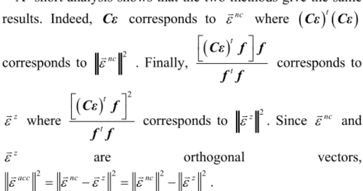
* * 2 t t t t t i T Cε f f Cε f f Cε f Cε Cε f f (30)A short analysis shows that the two methods give the same results. Indeed, Cε corresponds to where nc
tCε Cε corresponds to nc 2 . Finally,
t t Cε f f f f corresponds to z where
2 t t Cε f f f corresponds to 2 z . Since and nc z are orthogonal vectors,
2 2 2 2
acc nc z nc z
.
Equations (22) and (30) give then exactly the same results. However, the proposed vectorial approach has several advantages over the scalar approach.
n k1fk n f f f 1 : m n k k f ) ( ) ( : 1 n nc * / n k1fk k z + ‐ sc * / c * T * * i
n k sc k 1 2 Fig. 1. Block diagram of the proposed optimal current reference generator in real-time for a star-connected n-phase machine.
Firstly, the number of computations is reduced since no matrix calculations are needed. It is then possible to compute the current references in real-time, which is valuable for embedded systems with low memory capacity.
Finally, (22) gives a direct link between the current reference expressions and the physical parameters of the machine (SN-EMF), which does not seem the case when looking at (30).
Fig.1 gives the structure of the optimal current reference generator. n-dimensional variables are represented using a double line, scalar variables with a simple line.
V. OPTIMAL CONTROL OF A FIVE-PHASE DCBRUSHLESS MACHINE IN NORMAL AND OPEN-CIRCUITED PHASE
CONDITIONS
The computation of optimal current references in normal and the open-circuited phase mode is applied in this section to a star-connected surface mounted permanent magnet five-phase synchronous machine [22].
The rated power of the machine is 750 W with the rated voltage and current of 230 V and 5 A RMS respectively. The rated torque is 5 Nm and the rated speed is 1500 rpm.
The machine has two pole pairs and 20 slots with full pitched and concentrated windings. Four rows of 24 SmCo magnets with a residual flux density of 1.07 T are mounted on the rotor. Finally, stator resistance R=2.24 Ω.
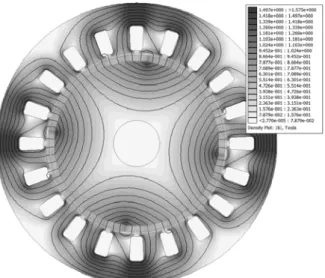
Fig.2 shows a 2D FEM analysis of the machine when the phases are supplied by a system of five balanced sinusoidal currents of 5 A RMS. Under the previous conditions, the back electromotive force is computed at 1500 rpm considering first that the material has a linear behaviour (L) and finally that the material has its real non linear behaviour (NL). It should be noted that, since there is no difference between the two plots in Fig.3, the assumption, that the magnetic saturation can be neglected, is validated for the chosen machine.
Table I gives the nine first harmonics of the speed normalized back-electromotive force of the machine considered in the paper.
TABLE I
NINE FIRST HARMONICS OF THE SPEED NORMALIZED BACK EMF
Harmonic rank 1 3 5 7 9
Fig. 2. 2D FEM analysis of the proposed machine supplied by five sinusoidal currents.
Fig. 3.Back electromotive force at 1500 rpm with linear and non linear magnetic behaviour.
A. Normal mode (The five phases are connected to the VSI) In this mode, since the machine is star-connected, currents cannot contain zero-sequence components (fifth harmonic and multiples). Current vector i is then a 5-1=4 dimensional vector.
In order to fulfil (7), the accessible SN-EMF vector must be restricted to the same subspace as the current vector. Then, accessible SN-EMF vector acc is computed using (31):
z acc (31) with: z 1 2 53 4 5.x1x2 x53x4 x5
the zero-sequence component of .
Criteria A and c are finally computed according to (8) and (9).
Since, for the machine under consideration, nine harmonics of speed normalized back-electromotive force are considered and the machine has five phases, acc 2 is not constant and the spectral content of current references is more significant than the spectral content of back-electromotive forces.
Fig. 4 shows the five SN-EMF and the associated optimal current references, for a torque reference of 2 Nm. in normal mode. Fig. 5 shows criterion A for this case. For a torque reference of 2 Nm and according to (11), Joule losses are estimated to be 32.3 W.
B. Open-circuited phase mode (one or two phases are disconnected from the supply)
The accessible SN-EMF vector is computed according to the circuited phases. For example, if phases 1 and 3 are open-circuited, accessible SN-EMF vector becomes the (5-3=2)-dimensional vector expressed in (32).
13 acc z (32) with: 13 1.x13x3 and: 3 . 3 5 4 2 5 4 2 x x x z
Fig. 6 shows the optimal current references obtained for several configurations: one, two non-adjacent and two adjacent open-circuited phases when the torque reference is set to 2 Nm Fig. 5 shows criterion A for each of these three cases.
For each functioning mode and keeping a torque reference of 2 Nm, Joule losses, according to (11), are as follows:
− One phase: 44 W (i.e. +36% compared to the normal mode)
− Two non-adjacent phases: 58 W (i.e. +79.6%) − Two-adjacent phases: 641 W (i.e. +1884%)
Whatever the functioning mode, if Joule losses have to be kept the same as in normal mode (i.e. 32.3W), the torque reference has to be reduced in order to fulfil (11):
− One phase: 1.71 Nm (i.e. -14.5%)
− Two non-adjacent phases: 1.49 Nm (-25.5%) − Two-adjacent phases: 0.449 Nm (-77.6%) C. Comparison with equivalent methods
The current references obtained by the proposed method have similar waveforms to those obtained via optimization with the Lagrangian approach expressed in [13]. However, compared to [13], the proposed method has several advantages: the references are computed in real-time and there is a direct link between the expected torque, the functioning mode and Joule losses. Finally, although this point is not developed in this paper, the harmonic content of current references can be mathematically computed in order to choose the best suited current controllers.
0 180 360 -0.4 -0.2 0 0.2 0.4 S N -E M F (V s ) 0 180 360 -4 -2 0 2 4 Rotor position (°) C u rre n ts (A ) i1 i2 i3 i4 i5 SN-EMF1 SN-EMF2 SN-EMF3 SN-EMF4 SN-EMF5
Fig. 4. Speed-normalized EMF and optimal current references in normal mode
0 180 360 6 10 14 Cr it e ri a ( A /V s ) nm 1op 2naop 0 180 360 0 2000 4000 Rotor position (°) Cr it e ri o n ( A /V s) 2aop
Fig. 5. Criteria A for normal mode (nm), one open-circuited phase (1po), two non-adjacent open-circuited phases (2naop) and two adjacent phases (2aop)
0 180 360 -5 0 5 C u rr e n ts (A ) 0 180 360 -5 0 5 C u rr e n ts (A ) 0 180 360 -50 0 50 Rotor position (°) Cu rr e n ts (A ) i2 i3 i4 i5 i2 i4 i5 i3 i4 i5
Fig. 6. Optimal current references with from top to bottom: one, two non-adjacent and two non-adjacent open-circuited phases
VI. SIMULATION RESULTS AND EXPERIMENTAL IMPLEMENTATION
A. Simulation results
The optimal control technique was simulated using a star-connected four-pole five-phase DC brushless machine with trapezoidal EMF supplied by a 5-leg Voltage Source Inverter (VSI).
Fig.7 shows the control structure of the overall system. The speed is regulated using a PI controller. The speed controller generates the torque reference. The optimal current reference generator computes the current references in real-time from the fault info vector and the mechanical position in order to estimate the SN-EMF vector (see Fig.1 for details).
For all tests, the DC Bus voltage has been set to 100 V DC, the speed reference to 20 rad/s and the load torque to 2 Nm. Since current references have complex shapes, currents are controlled using a hysteresis control whose bandwidth is sufficient.
To show the effectiveness of the proposed method, several tests under various configurations have been simulated.
Fig.8 shows the simulated phase currents for one, two non-adjacent and two non-adjacent open-circuited phases. These results are obtained using the current references shown in Fig.4 and Fig.6. The electromagnetic torque for each case is shown in Fig.9. For the first two cases, the torque is maintained constant and equal to the reference which has been set to 2 Nm. However, due to the high dynamics of current references, it is shown that it is not possible to obtain a constant torque with optimal current references when two adjacent phases are open-circuited. A solution can consist in reducing the number of considered SN-EMF harmonic in order to generate smoother current references. If the torque cannot be constant in this case, the torque ripples can be drastically reduced.
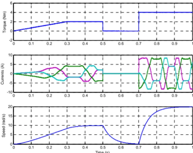
Finally, Fig.10 shows torque, currents and speed when two non-adjacent phases are open-circuited and when a varying torque reference is applied. These plots show the real-time generation of optimal current references.
PI d/dt Optimal current reference generator N* N + ‐ T* i
Rectifier VSI n‐phase PMSM
G r i d Hysteresis controller f i*
0 0.1 0.2 0.3 0.4 -5 0 5 C u rre n ts (A ) 0 0.1 0.2 0.3 0.4 -5 0 5 C u rre n ts (A ) 0 0.1 0.2 0.3 0.4 -20 0 20 Time (s) C u rre n ts (A )
Fig. 8. Simulated currents with, from top to bottom: one phase, two non-adjacent phases and two non-adjacent phases open-circuited
0 0.1 0.2 0.3 0.4 0 2 4 T o rq u e (N m ) 0 0.1 0.2 0.3 0.4 0 2 4 T o rque ( N m ) 0 0.1 0.2 0.3 0.4 0 2 4 Time (s) T o rq u e (N m )
Fig. 9. Simulated torques with, from top to bottom: one phase, two non-adjacent phases and two non-adjacent phases open-circuited
0 0.1 0.2 0.3 0.4 0.5 0.6 0.7 0.8 0.9 1 -2 0 2 4 6 T o rq u e (N m ) 0 0.1 0.2 0.3 0.4 0.5 0.6 0.7 0.8 0.9 1 -10 -5 0 5 10 C u rr e n ts ( A ) 0 0.1 0.2 0.3 0.4 0.5 0.6 0.7 0.8 0.9 1 0 5 10 15 20 Time (s) S p ee d ( ra d /s )
Fig. 10. Simulated torque, currents and speed when two non-adjacent phases are open-circuited and with a varying torque reference
B. Experimental implementation
The optimal control technique has been implemented on a star-connected four-pole five-phase DC brushless machine with trapezoidal EMF supplied by a 5-leg Voltage Source Inverter (VSI). Fig.11 gives a snapshot of the experimental test bed.
The load torque is generated by a magnetic powder brake associated with an inertial load. A torquemeter SCAIME DR2513 is installed between the motor and the load in order to measure the mechanical torque. The speed is estimated from the rotor position measured by a synchro-resolver. The overall system is controlled by a DS1005 controller board from DSpace®. The sampling time has been set to 100 µs.
For all tests, the DC Bus voltage has been set to 100 V DC, the speed reference to 20 rad/s and the load torque to 2 Nm. Since current references have complex shapes, currents are controlled using a hysteresis control whose bandwidth is sufficient.
To show the effectiveness of the proposed method, the same tests as in simulation have been carried out on the experimental test-bed.
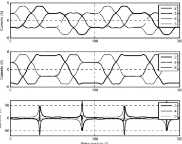
Fig.12 shows the experimental phase currents for one, two non-adjacent and two adjacent open-circuited phases. Fig.13 gives the corresponding estimated torques.
In Fig.14, one can see the improvement of the measured torque quality when one phase is open-circuited. Keeping the same references as in normal mode (See Fig. 4) leads to a torque with high amplitude harmonics. Using the optimal current references (see Fig.6) makes it possible to have a smoother torque as in normal mode.
0 0.02 0.04 0.06 0.08 0.1 0.12 0.14 0.16 0.18 -5 0 5 C u rr e n ts ( A ) 0 0.02 0.04 0.06 0.08 0.1 0.12 0.14 0.16 0.18 -5 0 5 C u rr e n ts ( A ) 0 0.02 0.04 0.06 0.08 0.1 0.12 0.14 0.16 0.18 -20 0 20 Time (s) Cu rr e n ts (A )
Fig. 12. Experimental currents with, from top to bottom: one phase, two non-adjacent phases and two non-adjacent phases open-circuited
0 0.02 0.04 0.06 0.08 0.1 0.12 0.14 0.16 0.18 0 1 2 3 4 To rq u e ( N m ) 0 0.02 0.04 0.06 0.08 0.1 0.12 0.14 0.16 0.18 0 1 2 3 4 To rq u e ( N m ) 0 0.02 0.04 0.06 0.08 0.1 0.12 0.14 0.16 0.18 0 1 2 3 4 Time (s) To rq u e ( N m )
Fig. 13. Experimental estimated torques with, from top to bottom: one phase, two non-adjacent phases and two adjacent phases open-circuited
0 0.02 0.04 0.06 0.08 0.1 0.12 0.14 0.16 0.18 0.2 0 0.5 1 1.5 2 2.5 3 3.5 4 Time (s) T o rque ( N .m )
with optimal references without optimal references
Fig. 14. Experimental measured torques with and without optimal current references for the case of one open-circuited phase.
VII. CONCLUSION
This paper shows how a vectorial approach simplifies the optimal current reference generation to minimize stator copper losses. Since the proposed method is not computational expensive, contrary to existing scalar methods, it can be implemented in real-time. The vectorial method is then particularly well suited for embedded systems with low memory capabilities.
It should be noted that the proposed method is only valid under the assumptions of no magnetic saturation and no saliency effect. Further studies are then in progress to show how the vectorial approach can be used to compute optimal current references according to other criteria, for example core losses.
REFERENCES
[1] E. Levi, “Multiphase electric machines for variable-speed applications”, IEEE Trans. Ind. Electron., vol. 55, no. 5, pp. 1893– 1909, May 2008.
[2] T. M. Jahns,“Improved reliability in solid-state ac drives by means of multiple independent phase-drive units.” IEEE Trans. Ind. Appl., pp 321-331, May-June 1980.
[3] L. de Lillo, L. Empringham, P. W. Wheeler, S. Khwan-On, C. Gerada, M. N. Othman, and X. Huang, “Multiphase power converter drive for fault-tolerant machine development in aerospace applications”, IEEE Trans. Ind. Electron., vol.57, no.2, pp.575-583, Feb. 2010.
[4] R. K. Gupta, K. K. Mohapatra, A. Somani, and N. Mohan, “Direct-matrix-converter-based drive for a three-phase open-end-winding AC machine with advanced features”, IEEE Trans. Ind. Electron., vol.57, no.12, pp.4032-4042, Dec. 2010.
[5] S. Williamson, S. Smith, C. Hodge, " Fault tolerance in multiphase propulsion motors", JMET, No. A4 2004, pp3-7, 2004.
[6] R. Fu, T.A. Lipo, "Disturbance-free operation of a multiphase current-regulated motor drive with an opened phase," IEEE Trans. Ind. Appl., vol.30, no.5, pp.1267-1274, Sep-Oct 1994.
[7] H.A. Toliyat, "Analysis and simulation of five-phase variable-speed induction motor drives under asymmetrical connections," IEEE Trans. Power Electron., vol.13, no.4, pp.748-756, Jul 1998. [8] J. Figueroa, J. Cros, P. Viarouge, "Polyphase PM brushless DC
motor for high reliability application", in Proc. EPE’03, Toulouse (France), Sept. 2003.
[9] N. Bianchi, S. Bolognani, M.D. Pre, "Strategies for the fault-tolerant current control of a five-phase permanent-magnet motor", IEEE Trans. Ind. Appl., vol.43, no.4, pp.960-970, July-Aug. 2007 [10] L. Parsa, H.A. Toliyat, "Fault-tolerant interior-permanent-magnet
machines for hybrid electric vehicle applications," IEEE Trans. Veh. Technol., vol.56, no.4, pp.1546-1552, July 2007.
[11] L. Parsa, H.A.Toliyat, "Fault-tolerant five-phase permanent magnet motor drives," in Proc. 39th IEEE IAS’04, Seattle, USA, Oct. 2004, vol.2, pp. 1048-1054.
[12] J. Wang, K. Atallah, D. Howe, "Optimal torque control of fault-tolerant permanent magnet brushless machines", IEEE Trans. Magn., vol. 39, no.5, pp. 2962-2964, Sept. 2003.
[13] S. Dwari, L. Parsa, "An optimal control technique for multiphase PM machines under open-circuit faults," IEEE Trans. Ind. Electron., vol.55, no.5, pp.1988-1995, May 2008.
[14] Z. Sun, J. Wang, G.W. Jewell and D. Howe, “Enhanced optimal torque control of fault-tolerant PM machine under flux-weakening operation”, IEEE Trans. Ind. Electron., vol.57, no.1, pp.344-353, Jan. 2010.
[15] F. Locment, E. Semail, X. Kestelyn, A. Bouscayrol, "Control of a seven-phase axial flux machine designed for fault operation", in Proc. IEEE IECON’06, Paris, France, November 7 – 10, 2006, pp. 1101-1107.
[16] F. Locment, E. Semail, X. Kestelyn, "Vectorial approach-based control of a seven-phase axial flux machine designed for fault operation", IEEE Trans. Ind. Electron., vol.55, no.10, pp.3682-3691, Oct. 2008.
[17] E. Semail, X. Kestelyn, F. Locment, “Fault tolerant multiphase electrical drives: The impact of design”, EPJ AP, Vol 43, n°2, Aug. 2008.
[18] H. M. Ryu, J. H. Kim, S. K. Sul, "Synchronous-frame current control of multiphase synchronous motor under asymmetric fault condition due to open phases", IEEE Trans. Ind. Appl., vol.42, no.4, pp.1062-1070, July-Aug. 2006.
[19] M.A Fnaiech, F.Betin, G.A Capolino and F. Fnaiech, “Fuzzy logic and sliding-mode controls applied to six-phase induction machine with open phases”, IEEE Trans. Ind. Electron., vol.57, no.1, pp.354-364, Jan. 2010.
[20] E. Semail, X. Kestelyn and A. Bouscayrol, "Right harmonic spectrum for the back-electromotive force of a n-phase synchronous motor", in Proc. 39th IEEE IAS’04, Seattle, USA, Oct. 2004, Vol. 1, pp.71-78.
[21] E. Semail, X. Kestelyn, A. Bouscayrol, "Sensitivity of a 5-phase brushless DC machine to the 7th harmonic of the back-electromotive force," in Proc. 35th IEEE PESC, Aachen, Germany,
June 2004, vol.6, no., pp. 4564-4570.
[22] X. Kestelyn, E. Semail, Y. Crevits, “Generation of on-line optimal current references for multi-phase permanent magnet machines with open-circuited phases”, in Proc. IEEE IEMDC, Miami, Florida, USA, May 3–6, 2009, pp.689 – 694.