This is an author-deposited version published in: https://sam.ensam.eu Handle ID: .http://hdl.handle.net/10985/7496
To cite this version :
Aleksandra BIERLA, Guillaume FROMENTIN, Jean-Michel MARTIN, Thierry LE MOGNE, Nicole GENET - Tribological aspect of lubrication in form tapping of high strength steel - Lubrication Science - Vol. 20, n°4, p.269-281 - 2008
For Peer Review
Tribological aspect of lubrication in form tapping of high strength steel.
Journal: Lubrication Science Manuscript ID: LS-07-0026.R1 Wiley - Manuscript type: Research Article
Date Submitted by the Author: n/a
Complete List of Authors: Bierla, Aleksandra; ENSAM CLUNY, LABOMAP Fromentin, Guillaume; ENSAM CLUNY, LABOMAP Martin, Jean; ECL LTDS
Le-Mogne1, Thierry; ECL LTDS Genet, Nicole; TOTAL France
For Peer Review
Tribological aspect of lubrication in form tapping of high strength steel. A. Bierla1, G. Fromentin1, J-M. Martin2, T. Le Mogne2, N. Genet3
LaBoMaP1, Dept. of Machining, ENSAM, rue Porte de Paris, 71250 Cluny, France LTDS2, Ecole Centrale de Lyon, 36 avenue Guy de Collongue, 69130 Ecully, France TOTAL France3, Centre de Recherche de Solaize, Chemin du Canal BP22 69360 Solaize
Cedex
Abstract:
This study aims at analyzing the tribochemical mechanisms of lubrication during the process of form tapping and consequently optimizing the formulation of the lubricant. In order to correlate the tribochemical reactions with the performance of a lubricant, we measure the alteration of tapping torque according to ASTM D5619 standard.
The objective of the study also relates to the identification of the additives and the association of their properties to the performance of lubrication. The goal is to characterize the nature of the tribofilm created at the bottom of the threads which is the zone the most severely affected by the working tool. X-ray Photoelectron Spectroscopy (XPS) is used to characterize the surface of formed threads.
This study demonstrates a link between the sulphur reactions on the metallic surface and the friction reducing performance of lubricant during form tapping.
Key words:
Form tapping; Metal Working Fluids; Additives; X-ray Photoelectron Spectroscopy
1. Introduction
The major role of lubricating oil is to decrease the friction between the tool and the workpiece and consequently reduce the cutting forces and the tool wear. In addition, the cutting fluids have to remove the heat due to metal deforming and perform the chemical reactions under boundary conditions with the workpiece surface to prevent welding of the tool [1,2]. Belluco and Chiffre [3,4] emphasize that the use of cutting fluid helps in achieving the desired dimensions and form, and the surface finish. The performance in terms of tool wear reduction is still the most important point though. The general composition of lubricating oil consists of the base oil to which a different number of additives are added.
Form tapping is a method of manufacturing an internal thread which differs from cut tapping. The thread is carried out without chip but with displacement of the work material. Figure 1 depicts the difference between the micrographs of cut and formed thread. The formation of the thread is obtained by the successive action of lobes of a tap. Each lobe causes a three-dimensional plastic flow [5,6]. This plastic flow leads to an important strain hardening of the work material (an increase close to 100% of initial hardness), which induces the tap wear.
(Figure 1. Micrographs of cut and formed thread.)
The characteristics of formed thread are quite different from those obtained by cut tapping. In addition of the absence of chip, using form tapping offers several benefits: an increased reliability, an increased tool life and finally better geometrical and mechanical characteristics of threads [7]. That’s why this process acquires greater importance for several mechanical industries such as the automotive sector.
The thread formation is a key point of the study of the form tapping. Parameters like the material, the tool geometry and the fluid modify it significantly [8]. The importance of the lubricant and the effect of its additives on the temperature and on the friction were proved during form tapping of high strength steels.
3 4 5 6 7 8 9 10 11 12 13 14 15 16 17 18 19 20 21 22 23 24 25 26 27 28 29 30 31 32 33 34 35 36 37 38 39 40 41 42 43 44 45 46 47 48 49 50 51 52 53 54 55 56 57 58 59 60
For Peer Review
The results show that in the case of form tapping of steels with lubrication, the fluid contributes to lubrication predominantly by a physicochemical process due to the additives it contains. Form tapping is a severe process of machining and the success of this operation often depends on the lubricant.
Several documents in the literature discuss the different testing methods, tool life and tool wear tests employed for the evaluation of efficiency of metalworking fluids [3,9]. The majority of authors agreed [1,3,4,10] that the performance evaluation should be based on machining tests rather than on tribological analyses. The machining tests provide more useful information because the test conditions and the contact geometries are close to those in practical operations. Nevertheless, this suggestion deals with the number of parameters which have to be considered such as machining conditions, tool material, workpiece material or machine tool. The tapping torque test used in this study is a standard test for evaluation and comparison of cutting fluids [11,12]. The oil containing efficient additives can significantly reduce the torque needed to form the thread, and as a result, the tool life increases with decreasing values of tapping torque.
This study consisted first in obtaining a coherent classification of the additives in the lubricant designed for a process of form tapping. After having established it, the experiment was conducted from the analytical side, using the techniques of surface analysis.
2. Experimental materials
2.1.The lubricants and the additives
During the form tapping tests, seven different blends were used. The experiments were carried out with blends consisting of paraffinic base oil (chemically active, containing sulphur components) and five different additives. Table 1 shows the available information about tested lubricants and their designation adapted for this study. The sulphurized water-based emulsion (concentration 5%wt.) was used during the machining of samples for the form tapping tests, that is turning, drilling and boring. The samples were cleaned carefully before the tapping tests.
(Table 1. Tested fluids and their designation.) 2.2. The tapping test materials
The essential of tapping tests was performed on a DMC65V (Deckel Maho Gildmeister) 3 axes vertical machining centre, equipped with the Siemens 840D CNC. The structure of machine is a gantry type, with a fixed table and a vertical axis Z. The forces which emerged during the form tapping were recorded using the Kistler 9173 force transducer (piezoelectric sensors). The force Fz and the torque Mz were recorded by analysing the phenomena occurring during the form tapping. Furthermore, the tapping torque is the main source of information used for comparing the performance of fluids. These measurements were made according to the ASTM D5619 standard test and the data were recorded in software acquisition. The lubrication is provided through the centre of the spindle. The work material was C70 carbon steel. Its ultimate strength is around 900 MPa. Due to sensor capacity, and in order to be representative of industrial practice, the tools used in the experiments were the M12x1.5 6HX taps. They are made of high speed steel, enriched with cobalt and TiN coated. The tap was composed of 5 lobes and a short entry taper with 3 pitches. Cutting fluids, as well as work and tool materials were selected from the same production batches.
2.3. The experimental procedure
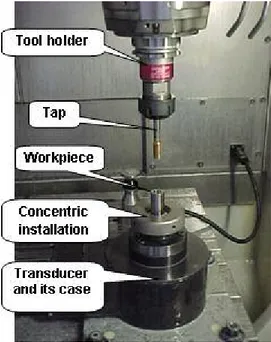
All the pieces of machining installation were cleaned in advance. The transducer and its case for protection were fixed on the table of the machining centre. The 20 mm-diameter
3 4 5 6 7 8 9 10 11 12 13 14 15 16 17 18 19 20 21 22 23 24 25 26 27 28 29 30 31 32 33 34 35 36 37 38 39 40 41 42 43 44 45 46 47 48 49 50 51 52 53 54 55 56 57 58 59 60
For Peer Review
cylinder workpieces were positioned in a concentric installation. Figure 2 presents the set up for the machining experiment.
(Figure 2. The set up for the machining experiment.)
The operation of drilling and boring of holes, adapted to the dimensions of threads M12*1.5, were realized using a sulphurized emulsion. This machining procedure provides an accurate hole diameter with a very good concentricity. The formation of thread (thread percentage) depends on it. This diameter is a very important parameter in form tapping and can have a considerable effect on the tapping torque [8,13].
The next step consisted in the fixation of the tap in the tool holder and filling the bored holes with test fluid. The torque developed during the tapping of each hole was monitored and recorded.
After that, the workpieces were cut (dry milling, cooled with compressed air) in order to obtain the pieces for XPS analysis. The cut parts of formed threads were just cleaned with compressed air and kept carefully until their analysis in an aluminium foil in enclosed bags (in air) (Figure 3).
(Figure 3. The cut parts of formed threads.) 2.4. Surface analysis
The wear areas were observed with analytical tools such as the X-ray Photoelectron Spectroscopy (XPS) and the Auger Electron Spectroscopy (AES). This paper presents however only the XPS analysis results. The XPS analysis was carried out with a Mg K (1253.4 eV) line excitation source (VG XR2). The X-ray power and analyzer resolution were 180W and 0.72 eV, respectively.
The detection was made by the VG ESCALAB 220i spectrometer equipped with a set of inlet and outlet lenses and an energy analyser. The VG EXO5 ion gun was used for ion etching and AES depth profiles [14].
All the residues of lubricants were ultrasonically removed from cut parts of formed threads in pure heptane just before the analysis. Afterwards, the pieces were introduced into the vacuum for analyses. The specimen surface was etched with Ar+ (5kV, 5x10⁻⁸ mbar, 3.75x3.75 mm2) three times for 15 minutes. The adventitious carbon was removed after first etching. XPS analyses were carried out inside the tribofilm.
Spectra were recorded and then treated using Advantage® software. A Shirley background was employed for the fitting of spectra. All XPS features were constrained with L/G ratio (60%) and FWHM. The relative intensities of the spin-orbit features for the S2p3/2 and S2p1/2 peaks were taken into account. Scofield sensitivity factors were applied for the determination of atomic percentages.
3. Tapping test results.
3.1. Tapping test results with the paraffinic base oil (F0).
Even though all the taps came from the same batch, it was decided to compare their behaviour in practical conditions. The aim of this procedure was to verify the presence of perturbations which could appear between the taps owing to the surface roughness or to the micro-differences in geometry. Each tap was tested using the same fluid F0 (paraffinic base oil). Before this operation, the taps were cleaned carefully in heptane using an ultrasonic bath.
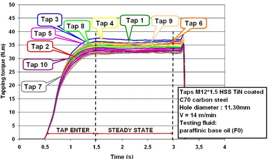
Figure 4 presents the results of the tapping test with the paraffinic base oil. The two graphs display the torque values obtained for 10 new (never used) taps. The first graph is the typical presentation of tapping torque evolution as a function of time. The average tapping torque is evaluated when all active lobes of tap are working to form the thread. This period of time corresponds to the quasi-stationary state included for this test of between 1.5 and 3
3 4 5 6 7 8 9 10 11 12 13 14 15 16 17 18 19 20 21 22 23 24 25 26 27 28 29 30 31 32 33 34 35 36 37 38 39 40 41 42 43 44 45 46 47 48 49 50 51 52 53 54 55 56 57 58 59 60
For Peer Review
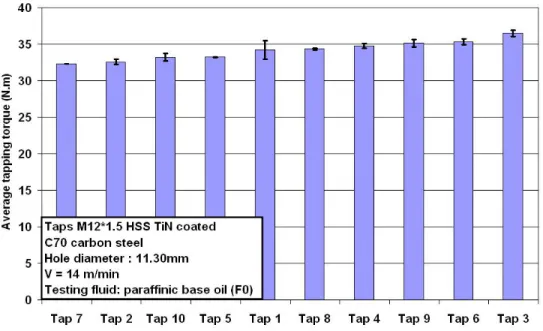
seconds. The second graph summarizes the results and gives the average torque values obtained for every tap. Error bars in this figure represent deviations. The tap numbers 1 and 3 were disqualified from the experiment for having unrepeatable results. The results for the rest of the taps showed a good repeatability of the tests (2%).
(Figure 4. Tapping test results with the paraffinic base oil.)
It can be clearly established that the tools performed the different effort to form the thread (different torque values). Indeed, it was ascertained that the difference in performance between the taps can attain 12%. The suggestion was made that effectively the differences in the results for tools are due to the microdifferences in their geometry or in their surface roughness. Thus, knowing the value of these dispersions between the taps, a coefficient of correction had to be applied for the later tests to assure their pertinence and the accurate classification of the lubricants. Each tap was used consequently only for one test lubricant in order to avoid any contamination of taps by the different chemical elements in the fluids. We suppose that the application of the correction coefficient is independent of the tested lubricant because the evaluated dispersions are attributed to the tool geometry not to the lubricant. Table 2 presents the evaluation of the correction coefficient for the taps.
(Table 2. Evaluation of the correction coefficient for the taps.) 3.2. Tapping tests results with the different fluids
During this part, the performance of seven different lubricants was tested and compared using the ASTM D5619 standard. The hole diameter was constant at 11.30mm. The tested taps were cleaned before form tapping in the same way as in the previous part.
The influence of seven tested fluids on tapping torque values is shown on two graphs below (Figure 5). The first graph presents the evolution of tapping torque for every tested fluid. It can be reported that the fluids F6 and F5 reveal the improvement of effectiveness in comparison with the others fluids. The second graph recapitulates the results and redresses the torque values measured for each fluid with a coefficient of correction found for every tap during the tapping test with the paraffinic base oil as defined by equation:
Average tapping torque corrected = Average tapping torque measured / Correction coefficient
The order of tapping efficiency of fluids can be listed as: F6>F5>F0>F3>F1>F2>F4. The fluid F6 (fully formulated oil) presented almost the same efficiency as a fluid F5 (blend of paraffinic base oil and ADD5 additive). The torque measurements recorded for the others blends were almost equivalent. Consequently, it can be deduced that the ADD5 additive gives all the effectiveness of lubrication to the fully formulated oil. The action of this additive decreased the torque value by about 15% during form tapping. The rest of the additives seemed not to have any important influence on the friction reduction between the tap and the work material.
(Figure 5. Tapping torque values obtained with different fluids.)
It can also be concluded from this experiment that the chemically active base oil could have the same performance as its blend with the ADD1, ADD2, ADD3 and ADD4 additives. This conclusion raises the question of the utility of using several additives in the lubricants instead of less complex mixtures which could lower or even equal average torque value. Nevertheless, the impact on the tool wear rate should be studied further. A good repeatability of the tests (2%) is shown in the results. Error bars in the figure represent deviations calculated from 3 repetitions.
3 4 5 6 7 8 9 10 11 12 13 14 15 16 17 18 19 20 21 22 23 24 25 26 27 28 29 30 31 32 33 34 35 36 37 38 39 40 41 42 43 44 45 46 47 48 49 50 51 52 53 54 55 56 57 58 59 60
For Peer Review
More detailed analyses are necessary in order to understand the reactions which occur on the surfaces during form tapping and to validate the conclusions deduced from the tapping tests. X-ray Photoelectron Spectroscopy was employed in the following part of the experiment.
3.3. Surface analysis of tapped specimens
The aim of this part of the study is to explain the tapping test results by demonstrating the presence of the chemical elements coming from the lubricants on the surface of formed threads. XPS analysis is used to in order to investigate their chemical states.
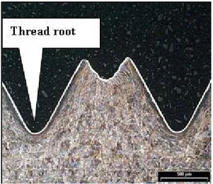
All the pieces were prepared in the same way according to the procedure mentioned in the paragraph 2.3. The threads formed with the two most efficient fluids (F6 and F5), and with two other fluids with less efficiency (F0 and F2), were submitted for examination. The 7th pitch is analyzed on every formed thread (thread root). Figure 6 shows this zone of thread that is the most deformed region because of heavy contact with the working tool.
(Figure 6. Analysed zone of formed thread.)
Electron binding energies in the XPS spectrum were calibrated against the carbon C1s main peak which is assumed to be 285 eV. The binding energy of C1s at 286 eV and 288 eV can be assigned to C-O bond and C=O bond respectively. The detailed data of some detected elements are listed in Table 2. The iron is the only metallic element whose concentration was sufficiently important to be taken into account.
(Table 3. Binding energies of some detected elements on formed threads with the different fluids during XPS analysis.)
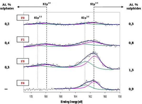
The binding energy of O1s at 530 eV can be attributed to existence of iron oxides. The most interesting information however was provided by the chemical shifts of sulphur and its atomic percentage. Figure 7 depicts the XPS spectra of sulphur. An important peak of sulphides at 161.5 eV was detected on the surface of formed threads using the two most efficient fluids - F6 (fully formulated oil) and F5 (paraffinic base oil + ADD5).
There is no peak at 163 eV which could be attributed to sulphur in the additive or elemental sulphur. The hypothesis was made that the sulphur bonds in the additive broke down and liberated sulphur which reacted with metallic iron to form iron sulphides. Iron sulphides as reaction products of lubricant with metallic surface are well known for their very good anti-seizure and anti-welding behaviour in extreme conditions such as machining (high temperature, pressure). It was impossible to specify the chemical form of this compound at this stage of experiment though (FeS or FeS2). This point should be studied more precisely.
The sulphide peak is considerably less important on the spectrum of fluid F2 (paraffinic base oil + ADD2) and hardly detectable in the case of fluid F1 (paraffinic base oil). Another peak of sulphur close to 168 eV can be attributed to sulphates. It is difficult to determine however the role and the process of sulphate formation for tested fluids (sulphur additive decomposition product or/and sulphides oxidation product during experiment or during storage). It was inferred that the lack of a sulphates peak on the sulphur spectrum for threads realized with F6 (fully formulated oil) could be due to the anti-oxidant additive contained in its blend.
The main peak of iron detected on the surface is situated at 710 eV (Fe2+) while there is no peak detected at 707 eV that could correspond to the metallic iron (Fe0). This peak can be attributed to iron sulphides and/or metallic oxides but it is difficult to identify them precisely on the iron spectrum. It can be supposed that these two reactions underwent because of the presence of metallic oxides and iron sulphides on oxygen and sulphur spectra, respectively. 3 4 5 6 7 8 9 10 11 12 13 14 15 16 17 18 19 20 21 22 23 24 25 26 27 28 29 30 31 32 33 34 35 36 37 38 39 40 41 42 43 44 45 46 47 48 49 50 51 52 53 54 55 56 57 58 59 60
For Peer Review
These results could be interpreted as evidence that the performance of a fluid depends on the sulphur reactivity with the surface. The presence of iron sulphides on the surface of the formed thread with the fully formulated oil and blend F5 was the reason for the good performance of these two lubricants.
(Figure 7. Chemical shifts of sulphur peak and its atomic percentage on the surfaces of formed threads with F0, F2, F5 and F6 fluid (XPS analysis).)
4. Conclusions
Tapping is a delicate operation of machining which intervenes often at the end of the manufacturing process and thus it is crucial to control it. A failure to do so leads to the rejection of the work piece which causes a financial loss related to waste and to the previously added value by the other operations of machining.
An improvement in percentage efficiency was obtained with a mixture of paraffinic base oil containing the ADD5 additive (a sulphur containing additive). Furthermore, iron sulphide spectra were detected on the tapped surface, the existence of which was proposed as being responsible for its corresponding performance.
The comprehension of the nature of the tribofilm created at the lubricated interface signifies the understanding of the additive behaviour. The role and the action of additives is a key matter for further exploration and optimization of the metalworking fluids. Also, it has been shown that the form tapping test can be a pertinent method of lubricant evaluation and it can help to compare the different additives.
The poor effect of additives (tapping torque decreased by only 15%), added to the chemically active paraffinic base oil, has to be highlighted as well. It could be possible however that the additives included in the chemically non active paraffinic base oil would justify their use and have a greater impact on the decrease of tapping torque values.
This study also raises the question of the utility of using several additives in the lubricants instead of mixtures less complex which could have equal or even better than equal performance.
5. Acknowledgements
The authors would like to express their appreciation to the TOTAL France Co. for their contribution to this study.
6. References
[1] Hong H., Riga A.T., Cahoon J.M., Vinci J.N. The chemistry of sulfonates as metalworking additives. Lubrication engineering 1994; 50(2), pp. 155-158
[2] Chen Haigang, Wu Xuedong, Yang Shengrong, Zou Ling, Wang Dapu. The tribological behaviors of various metallic cations in tapping of a titanium alloy. Wear 2001; 247, pp. 120-123
[3] De Chiffre L., Belluco W. Investigations of cutting fluid performance using different machining operations. Lubrication engineering 2002; 58(10), pp.22-29
[4] De Chiffre L., Belluco W. Surface integrity and part accuracy in reaming and tapping stainless steel with new vegetable based cutting oils. Tribology International 2002; 35, pp.865- 870 3 4 5 6 7 8 9 10 11 12 13 14 15 16 17 18 19 20 21 22 23 24 25 26 27 28 29 30 31 32 33 34 35 36 37 38 39 40 41 42 43 44 45 46 47 48 49 50 51 52 53 54 55 56 57 58 59 60
For Peer Review
[5] Fromentin G., Poulachon G., Moisan A. An experimental and analytical method for investigating plastic flow in form tapping. International Journal of Forming Processes 2006; 9(4)
[6] Warrington C., DeVor R., Kapoor S. Finite element modelling for tap design improvement in form tapping. ASME Journal of Manufact.& Eng. Tech 2006; 128(65)
[7] Fromentin G., Poulachon G., Moisan A. Precision and surface integrity of internal threads obtained by form tapping. Manufacturing Technology, CIRP Annals 2005; 54(1), pp. 519-522 [8] Fromentin G. Etude mécanique et technologique du taraudage par déformation : application aux aciers prétraités. PhD thesis ; ENSAM Cluny 2004
[9] De Chiffre L., Belluco W. Comparison of methods for cutting fluid performance testing.
Annals of the CIRP 2000; 49(1), pp. 57-60
[10] Hong H. Machinability of steels and titanium alloys under lubrication. Wear 1993; 162-164, pp. 34-39
[11] ASTMD5619 Standard test method for comparing metal removal fluids using the tapping torque test machine; American Society for Testing and Materials 2000
[12] NordTest MECH 039 Tapping torque test for cutting fluid evaluation; NordTest Method 1998
[13] Agapiou JS. Evaluation of the effect of high speed machining on tapping. Journal of
Manufacturing Science & Engineering Technology ASME 1994; 116, pp. 457-462
[14] Le Mogne Th., Martin J.-M., Grossiord C. Imaging the chemistry of transfer films in the AES/ XPS analytical UHV tribotester. Leeds-Lyon Symposium 1998; pp. 75-84
3 4 5 6 7 8 9 10 11 12 13 14 15 16 17 18 19 20 21 22 23 24 25 26 27 28 29 30 31 32 33 34 35 36 37 38 39 40 41 42 43 44 45 46 47 48 49 50 51 52 53 54 55 56 57 58 59 60
For Peer Review
(Table 1. Tested fluids and their designation.)(Table 2. Evaluation of the correction coefficient for the taps.) Fluid
designation adapted for this work
Composition of fluids and additive concentration
Nature of tested fluids
F0 PBO paraffinic base oil
F1 PBO+ADD1 (0,75% wt.) paraffinic base oil + additive
antioxidant, anti-foaming agent, anti-fogging agent
F2 PBO +ADD2 (1% wt.) paraffinic base oil + additive
antiwear 1
F3 PBO +ADD3 (2,5% wt.) paraffinic base oil + additive
antiwear 2
F4 PBO +ADD4 (10% wt.) paraffinic base oil + ester
additive
F5 PBO +ADD5 (3% wt.) paraffinic base oil + S
additive
F6 PBO+ADD1+ADD2+ADD3+ADD4+ADD5 fully formulated oil
-paraffinic base oil contained five additives
TAP Tap 2 Tap 4 Tap 5 Tap 6
Average tapping torque per tap [N.m] 32,57 34,77 33,22 35,34 Average tapping torque for all taps [N.m] 34,16
Correction coefficient of the tap 0,95 1,02 0,97 1,03
TAP Tap 7 Tap 8 Tap 9
Average tapping torque per tap [N.m] 32,32 34,33 35,13 Average tapping torque for all taps [N.m] 34,16
Correction coefficient of the tap 0,95 1,00 1,03
3 4 5 6 7 8 9 10 11 12 13 14 15 16 17 18 19 20 21 22 23 24 25 26 27 28 29 30 31 32 33 34 35 36 37 38 39 40 41 42 43 44 45 46 47 48 49 50 51 52 53 54 55 56 57 58 59 60
For Peer Review
(Table 3. Binding energies of some detected elements on formed threads with the different fluids during XPS analysis.)
Thread obtained with the fluid S2p3 O1s C1s Fe2p3 Peak BE At. % Peak BE At. % Peak BE At. % Peak BE At. % F0 161.6 0.3 530.0 23 284.8 42 710.1 9 168.1 0.2 531.6 12 286.1 6 532.9 4 288.2 3 F2 161.7 0.8 529.9 20 284.8 47 710.1 8 167.9 0.4 531.4 10 286.9 5 532.6 4 288.7 3 F5 161.4 1.3 530.0 22 284.9 41 709.8 11 167.8 0.3 531.4 10 286.4 4 532.4 5 288.9 3 F6 161.5 0.9 530.1 19 284.9 42 710.0 9 531.6 13 286.9 2 532.6 4 289.0 3 3 4 5 6 7 8 9 10 11 12 13 14 15 16 17 18 19 20 21 22 23 24 25 26 27 28 29 30 31 32 33 34 35 36 37 38 39 40 41 42 43 44 45 46 47 48 49 50 51 52 53 54 55 56 57 58 59 60
For Peer Review
Figure 1. Micrographs of cut and formed thread.
128x62mm (96 x 96 DPI) 3 4 5 6 7 8 9 10 11 12 13 14 15 16 17 18 19 20 21 22 23 24 25 26 27 28 29 30 31 32 33 34 35 36 37 38 39 40 41 42 43 44 45 46 47 48 49 50 51 52 53 54 55 56 57 58
For Peer Review
Figure 2. The set up for the machining experiment.
63x80mm (96 x 96 DPI) 3 4 5 6 7 8 9 10 11 12 13 14 15 16 17 18 19 20 21 22 23 24 25 26 27 28 29 30 31 32 33 34 35 36 37 38 39 40 41 42 43 44 45 46 47 48 49 50 51 52 53 54 55 56 57 58
For Peer Review
Figure 3. The cut parts of formed threads.
137x49mm (96 x 96 DPI) 3 4 5 6 7 8 9 10 11 12 13 14 15 16 17 18 19 20 21 22 23 24 25 26 27 28 29 30 31 32 33 34 35 36 37 38 39 40 41 42 43 44 45 46 47 48 49 50 51 52 53 54 55 56 57 58
For Peer Review
Figure 4. Tapping test results with the paraffinic base oil.
256x159mm (96 x 96 DPI) 3 4 5 6 7 8 9 10 11 12 13 14 15 16 17 18 19 20 21 22 23 24 25 26 27 28 29 30 31 32 33 34 35 36 37 38 39 40 41 42 43 44 45 46 47 48 49 50 51 52 53 54 55 56 57 58
For Peer Review
Figure 4. Tapping test results with the paraffinic base oil.
256x159mm (96 x 96 DPI) 3 4 5 6 7 8 9 10 11 12 13 14 15 16 17 18 19 20 21 22 23 24 25 26 27 28 29 30 31 32 33 34 35 36 37 38 39 40 41 42 43 44 45 46 47 48 49 50 51 52 53 54 55 56 57 58
For Peer Review
Figure 5. Tapping torque values obtained with different fluids.
256x159mm (96 x 96 DPI) 3 4 5 6 7 8 9 10 11 12 13 14 15 16 17 18 19 20 21 22 23 24 25 26 27 28 29 30 31 32 33 34 35 36 37 38 39 40 41 42 43 44 45 46 47 48 49 50 51 52 53 54 55 56 57 58
For Peer Review
Figure 5. Tapping torque values obtained with different fluids.
256x159mm (96 x 96 DPI) 3 4 5 6 7 8 9 10 11 12 13 14 15 16 17 18 19 20 21 22 23 24 25 26 27 28 29 30 31 32 33 34 35 36 37 38 39 40 41 42 43 44 45 46 47 48 49 50 51 52 53 54 55 56 57 58
For Peer Review
Figure 6. Analysed zone of formed thread.
69x60mm (96 x 96 DPI) 3 4 5 6 7 8 9 10 11 12 13 14 15 16 17 18 19 20 21 22 23 24 25 26 27 28 29 30 31 32 33 34 35 36 37 38 39 40 41 42 43 44 45 46 47 48 49 50 51 52 53 54 55 56 57 58
For Peer Review
Figure 7. Chemical shifts of sulphur peak and its atomic percentage on the surfaces of formed threads with F0, F2, F5 and F6 fluids(XPS analysis).
197x146mm (96 x 96 DPI) 3 4 5 6 7 8 9 10 11 12 13 14 15 16 17 18 19 20 21 22 23 24 25 26 27 28 29 30 31 32 33 34 35 36 37 38 39 40 41 42 43 44 45 46 47 48 49 50 51 52 53 54 55 56 57 58