Science Arts & Métiers (SAM)
is an open access repository that collects the work of Arts et Métiers Institute of
Technology researchers and makes it freely available over the web where possible.
This is an author-deposited version published in: https://sam.ensam.eu Handle ID: .http://hdl.handle.net/10985/8684
To cite this version :
Seifeddine BENELGHALI, Mohamed BENBOUZID, Jean-Frederic CHARPENTIER - Generator Systems for Marine Current Turbine Applications: A Comparative Study - Journal of Oceanic Engineering - Vol. 37, n°3, p.554-563 - 2012
Any correspondence concerning this service should be sent to the repository Administrator : [email protected]
Generator Systems for Marine Current Turbine
Applications: A Comparative Study
Seifeddine Benelghali, Member, IEEE, Mohamed El Hachemi Benbouzid, Senior Member, IEEE, and
Jean Frédéric Charpentier, Member, IEEE
Abstract—Emerging technologies for marine current turbines are mainly related to works that have been carried out on wind turbines and ship propellers. It is then obvious that many electric generator topologies could be used for marine current turbines. As in the wind turbine context, doubly-fed induction generators and permanent magnet generators seem to be attractive solutions for harnessing the tidal current energy. In this paper, a comparative study between these two generator types is presented and fully an-alyzed in terms of generated power, maintenance, and operation constraints. This comparison is done for the Raz de Sein site (Brit-tany, France) using a multiphysics modeling simulation tool. This tool integrates, in a modular environment, the resource model, the turbine hydrodynamic model, and generator models. Experiments have also been carried out to confirm the simulation results.
Index Terms—Control, doubly-fed induction generator, marine current turbine, modeling, permanent magnet synchronous gener-ator.
NOMENCLATURE
MCT Marine current turbine.
DFIG Doubly-fed induction generator.
PMSG Permanent magnet synchronous generator. MPPT Maximum power point tracking.
Fluid density (kg/m ).
Cross-sectional area of the marine turbine (m ). Fluid speed (m/s).
Tip speed ratio. Power coefficient. Tide coefficient.
Spring (neap) tide current speed (m/s). Stator (rotor) index (superscripts).
Manuscript received May 12, 2011; revised January 10, 2012; accepted April 15, 2012. Date of publication June 04, 2012; date of current version July 10, 2012.
Guest Editor: Y. Li.
S. Benelghali is with the University of Aix-Marseille 3, UMR CNRS 6168 LSIS, 13397 Marseille Cedex 20, France (email: seifeddine.benelghali@lsis. org).
M. E. H. Benbouzid is with the University of Brest, EA 4325 LBMS, 29238 Brest Cedex 3, France (e-mail: [email protected]).
J. F. Charpentier is with the French Naval Academy, EA 3634 IRENav, 29240 Brest Cedex 9, France (e-mail: [email protected]).
Synchronous reference frame index. Voltage (V) [current (A)].
Active (reactive) power (W). Flux (Wb).
Electromagnetic torque (mechanical torque) (Nm).
Resistance .
Inductance (mutual inductance) (H).
Total leakage coefficient, . Rotor position (rad).
Angular speed (synchronous speed) (rad/s or r/min).
Viscosity coefficient (Nm/s). Rotor Inertia (kg m ). Pole pair number.
I. INTRODUCTION
C
ONSIDERING the main projects for harnessing tidal en-ergy, it can be noticed that many technological solutions have been proposed and tested to find the optimal ones [1]. Therefore, it is necessary to develop simulation environments to estimate marine current turbine global behavior and poten-tial energy capture from the various sites. For that purpose, the authors have previously elaborated on such an environment [2], [3]. Indeed, this tool associates the resource model, the hydrody-namic turbine model, and electrical generator models in a mul-tiphysics approach. These models are integrated in the Matlab-Simulink® environment as Simulink blocks. This method al-lows a good modularity of the simulator. Therefore, this MCT simulator is very useful for estimating the relevance of a tech-nological solution for a given site [4].In this paper, this MCT simulator is used to estimate the har-nessed power from a DFIG- and PMSG-based MCT. To high-light differences between the considered technologies, a vari-able-speed control approach based on an MPPT strategy is used to carry out simulations and experiments. The two technology choices are then fully analyzed in terms of generated power, maintenance, and operating constraints.
II. MARINECURRENTTURBINEMODELING
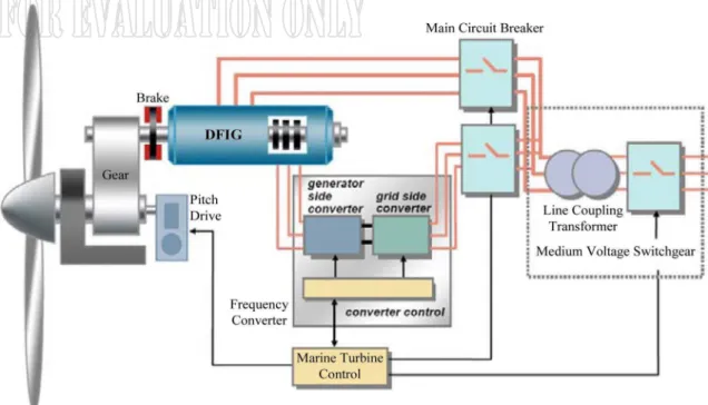
The global scheme for a grid-connected marine current tur-bine is given by Fig. 1. Considering this scheme, it can be
no-BENELGHALI et al.
Fig. 1. Marine current turbine global scheme.
Fig. 2. Harnessed tidal power and power ratings versus MCT diameter.
ticed that a global multiphysics approach must be considered to study the behavior of an MCT. So a simulation tool able to pre-dict the behavior of such a system must comprise the resource, the hydrodynamic turbine, the generator, the drive, and grid con-nection models [2], [3].
A. The Resource Model
1) Resource Potential: The total kinetic power in a marine
current turbine has a similar dependence to that of a wind turbine and is governed by[5]
(1) However, an MCT can only harness a fraction of this power due to losses, and (1) is modified as follows:
(2) For MCTs, is estimated to be in the range 0.35–0.5 [1]. Thus, the extracted power depends mainly on the tidal velocities and the turbine sizes (Fig. 2).
2) Resource Model: Tidal current data are given by the
French Navy Hydrographic and Oceanographic Service at hourly intervals starting at 6 h before high waters and ending 6 h after. Therefore, knowing the tide coefficient , a simple
Fig. 3. Tidal velocity in the Raz de Sein for the year 2007 and March 2007 [3].
and practical model for tidal current speeds has been derived [2]
(3) where 95 and 45 are, respectively, the spring and neap tide medium coefficients.
It can be noticed that an MCT experiences less perturba-tions than wind turbine because they are immerged systems. For MCTs, the main perturbation is the swell effect. Nevertheless, this study is limited to normal operating conditions and does not include swell and other disturbance effects which were pre-viously presented and analyzed in [6].
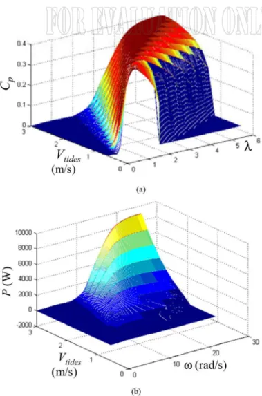
Fig. 4. Calculated hydrodynamics performance of a 1.44-m diameter turbine. (a) curves. (b) The extractable power .
This first-order model (3) is then used to calculate the tidal velocity each hour. The implemented model will allow the user to compute tidal velocities in a predefined time range (Fig. 3) [3].
B. The Turbine Rotor Model
The blade element momentum (BEM) method has been used for the marine turbine rotor modeling [7]. Fig. 4 shows some performance results obtained with this method for a 1.44-m di-ameter three-blade rotor [2]. The studied turbine is an open flow (nonducted) classical horizontal axis one.
C. The Generator Model
Much of the technology that has been suggested for tidal cur-rent energy extraction is reminiscent of that used for wind ap-plications. It is then obvious that some wind electric generator topologies could be used for marine turbines [1]. Table I briefly summarizes the pros and cons of the major generator topologies. In this table, many topologies seem a priori to be exploitable for tidal turbines.
In this paper, we chose to focus on two of these generator technologies. The first one is the DFIG which is extensively used for wind turbines [8], [9].
This system, which is one of the main adopted technologies for wind turbines, results in lower converter costs and lower power losses compared to a system based on a fully-fed syn-chronous generator with full-rated converter. Nevertheless, this generator has two main drawbacks: the limited speed range and the need for regular maintenance even if the DFIG is considered a robust system [10].
The second one is the PMSG. It was chosen because this tech-nology is characterized by a low maintenance level and high compactness, and allows using nonconventional solutions for the turbine generator integration [11]–[16]. These points appear to be particularly suitable in the marine context. Other technolo-gies appear not to be very suitable for MCTs due to the cons summarized in Table I.
1) DFIG Model: The DFIG offers several advantages
in-cluding variable-speed operation, and four-quadrant active and reactive power capabilities [10], [17]. Such a system also re-sults in lower converter costs and lower power electronics losses compared to a system based on a fully-fed synchronous gener-ator with full-rated converter.
The control system is usually defined in the synchronous frame fixed to either the stator voltage or the stator flux [17]. The generator dynamic model written in a synchronously rotating frame is given by (a schematic diagram of a DFIG-based generation system is shown in Fig. 5)
(4)
2) PMSG Model: The PMSG choice allows direct-drive
sys-tems that avoid gearbox use [11]–[13], [16]. This solution is very advantageous as it leads to low maintenance constraints. However, in such design, the generator is completely decou-pled from the grid by a voltage source full power converter (AC/DC/AC) connected to the stator (Fig. 6).
The PMSG dynamic equations are expressed in the synchro-nously rotating reference frame. The electrical dynamics model in terms of voltage and current can be given as [2]
(5) The electromagnetic torque in the rotor is written as
BENELGHALI et al.
TABLE I
GENERATORTOPOLOGIESCOMPARISON
III. MARINECURRENTTURBINEVARIABLE-SPEEDCONTROL
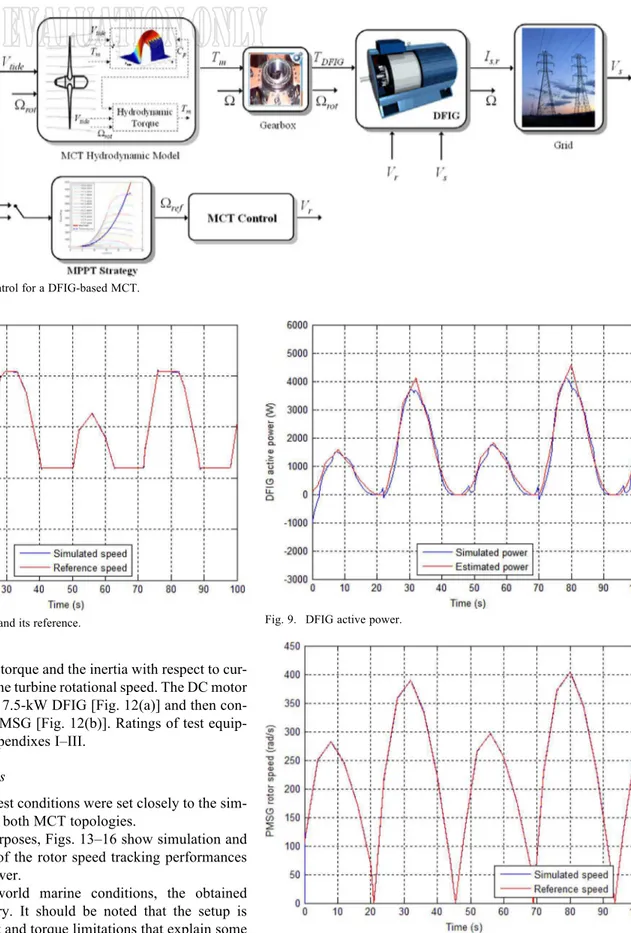
To illustrate the speed control, a low-power variable-speed fixed-pitch MCT-driven DFIG and PMSG have been sim-ulated. The proposed variable-speed control strategy is based on an MPPT. First, the optimal speed reference at each time is computed from the tidal velocity knowledge. This speed refer-ence corresponds to the maximum power which can be mechan-ically extracted by the turbine for the fluid velocity value. Then, classicalspeedcontrolofthegeneratorensuresthattherotorspeed converges to based on PI control. The above proposed con-trol strategy for a DFIG-based MCT is illustrated in Fig. 7.
For speed references given by the MPPT strategy, the DFIG-based MCT control performance is shown in Figs. 8 and 9, re-spectively, illustrating the rotor speed tracking performance and the generated active power.
The simulation time has been reduced to seconds to limit the computation time to realistic ones. In real-world application, the system mechanical dynamics will be slower than in simulations. Therefore, the MCT inertia was reduced in simulations to take into account the reduced calculation time. The variable-speed control strategy is tested by using a resource first-order model for a marine current turbine of 1.44-m diameter and 7.5-kW DFIG. This low power corresponds to the test model used for experimental validation in Section IV.
The main merit of the DFIG is its capability to deliver con-stant voltage and frequency output for 30% speed variation around conventional synchronous speed. It is also possible to extend the speed variation range from 30% to 50%, however this requires a larger power converter.
The same variable-speed strategy has been adopted for the PMSG-based MCT control. The obtained results show good
Fig. 5. Schematic diagram of a DFIG-based generation system.
Fig. 6. Schematic diagram of a PMSG-based generation system.
tracking performance for the PMSG rotor speed (Fig. 10). Fig. 11 illustrates the generated active power. While real-world applications might take advantage of a direct-drive PMSG, the simulations presented here use a geared PMSG to be able to compare them with experimental data. Indeed, experiments were carried out in a test bench using a geared PMSG driven by a DC motor that emulates hydrodynamic loads as shown in Section IV [2]. This geared PMSG is able to follow the MPPT in all the speed range. Therefore, as a first approach, it will have the same behavior as the direct-drive system in terms of harnessed energy (excluding the supplementary losses introduced by the gearbox).
In the two cases there are minor differences between the pre-dicted and simulated power. These differences are mainly due
to the type of control which is based on speed control and not on a direct power control.
It can be noticed that the harnessed global power is bigger with a PMSG-based MCT than with a DFIG-based one. This is mainly due to the limited speed range of the system. Indeed, the DFIG cannot reach the MPPT strategy required speed for all the tidal velocities. This point will be more detailed in Section V.
IV. EXPERIMENTALTESTS
A. Experimental Setup
Experiments were carried out on the experimental setup illus-trated in Fig. 12 [2]. This setup allows the physical simulation of a marine power system. The MCT is emulated by a DC motor,
Fig. 7. Variable-speed control for a DFIG-based MCT.
Fig. 8. DFIG rotor speed and its reference.
which reproduces the torque and the inertia with respect to cur-rent tidal speeds and the turbine rotational speed. The DC motor is first connected to a 7.5-kW DFIG [Fig. 12(a)] and then con-nected to a 7.5-kW PMSG [Fig. 12(b)]. Ratings of test equip-ment are given in Appendixes I–III.
B. Experimental Tests
The experimental test conditions were set closely to the sim-ulation conditions for both MCT topologies.
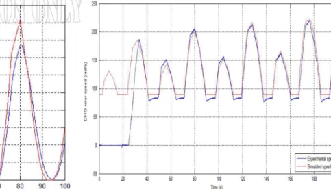
For comparison purposes, Figs. 13–16 show simulation and experimental results of the rotor speed tracking performances and the generated power.
Considering real-world marine conditions, the obtained results are satisfactory. It should be noted that the setup is equipped with current and torque limitations that explain some of Figs. 14 and 16 differences, particularly for high power generation.
V. GENERATORTOPOLOGYCOMPARATIVESTUDY
The comparison of different generator systems in the liter-ature is generally discussed with criteria based on the energy
Fig. 9. DFIG active power.
Fig. 10. PMSG rotor speed and its reference.
yield and cost. In this study, the comparative criterion is the cap-tured energy regarding the MCT topology and the effect of the variable-speed range.
The DFIG appears slightly more advantageous than the PMSG since it is a lightweight and low-cost concept [18], [19].
Fig. 11. PMSG active power.
Fig. 12. The experimental setup emulating a marine current turbine [ c G2ELAB Grenoble, France]: (a) DC motor, DFIG; (b) DC motor,
PMSG; and (c) power electronics for driving the DC motor, power electronics for driving the DFIG and the PMSG, DSP TMS320F240 implementing DC motor control, DSP DS1005 (dSPACE) implementing DFIG- and PMSG-based MCT controls.
Indeed, the converter for DFIG-based MCT is dimensioned only for 25% of the rated power, which justifies the success of these systems for wind applications. But the particular con-text of marine applications imposes different constraints. The marine current turbine will be installed in sites with strong cur-rents and difficult access. Therefore, minimizing maintenance is a fundamental aspect. A direct-drive PMSG requires less maintenance than the DFIG which needs regular maintenance for the gearbox and the slip rings.
Fig. 13. Experimental and simulated DFIG rotor speed tracking performances.
Fig. 14. DFIG output power: experiments versus simulation.
Fig. 15. Experimental and simulation PMSG rotor speed tracking perfor-mances [2].
For the first criterion, the annual produced power was calcu-lated for the two generator systems based on tidal current data from the Raz de Sein (Brittany, France), using a 10-m diam-eter and 100-kW turbine. These power ratings correspond to
BENELGHALI et al.
Fig. 16. PMSG output power: experiments versus simulation [2].
Fig. 17. Raz de Sein site tidal histogram.
the major prototypes that have been recently tested [1]. Fig. 17 shows the Raz de Sein site tidal histogram, and Figs. 18 and 19 illustrate the annual power extracted by each generator system for the above MCT rated power.
In this case and for calculation time reasons, simulations are only based on the use of the resource and the turbine hydrody-namic model. This means that the turbine generator speed con-trol is considered to be able to perfectly track the MPPT refer-ence speed. This assumption appears to be realistic considering simulations and experiments in low power cases previously pre-sented in Figs. 14 and 16.
The harnessed power from DFIG-based MCT is estimated to be about 1530 MWh/year. However, the PMSG-based MCT can extract up to 1916 MWh/year. Thus, over a year, there is a differ-ence of about 25% between the two generator systems and this percentage will grow when using a larger turbine. This differ-ence is due to speed restrictions imposed on the DFIG. Indeed, the speed references are limited to 30% of the rated speed. These limited speeds, when imposed as reference, correspond generally to a poor leading to a reduced extracted power.
Fig. 18. DFIG-based MCT harnessed energy histogram in one year.
Fig. 19. PMSG-based MCT harnessed energy histogram in one year.
Fig. 20. Rim-driven prototype integrating a radial permanent magnet gener-ator.
VI. CONCLUSION
According to the comparative study based on simulation and experiments, the PMSG-based MCT has the highest en-ergy yield. It can be concluded that, if solutions based on a doubly-fed induction generator have been very successful for wind turbine applications due to the low converter cost, it is probably not the case in marine turbine applications, except in
special cases where regular maintenance is possible. Moreover, PMSG direct drives seem much more applicable for marine applications which require very robust and maintenance-free systems. In this case, the system cost increase is compensated by a higher amount of harnessed energy and lower maintenance constraints.
In this context, the presented study will be further extended to include direct-drive systems. In fact, a rim-driven prototype has been built and its performance will be evaluated and compared to the above classical topologies (Fig. 20).
APPENDIXI
PARAMETERS OF THESIMULATED ANDTESTEDDFIG
0.455 0.084 H 0.62 0.081 H 0.078 H 0.3125 kg m 6.73 10 Nms APPENDIXII
PARAMETERS OF THESIMULATED ANDTESTEDPMSG
7.5 kW 3000 r/min, 22 Nm 0.173 m 0.085 mH 0.951 mH 0.112 Wb 0.0048 kg m 8.5 10 Nms APPENDIXIII
PARAMETERS OF THEDC MOTOR
6.5 kW 3850 r/min, 310 V, 24.8 A 78 0.78 3.6 H 0.02 kg m REFERENCES
[1] S. Benelghali, M. E. H. Benbouzid, and J. F. Charpentier, “Marine tidal current electric power generation technology: State of the art and cur-rent status,” in Proc. IEEE Int. Electr. Mach. Drives Conf., Antalya, Turkey, May 2007, vol. 2, pp. 1407–1412.
[2] S. Benelghali, M. E. H. Benbouzid, J. F. Charpentier, T. Ahmed-Ali, and I. Munteanu, “Experimental validation of a marine current turbine simulator: Application to a PMSG-based system second-order sliding mode control,” IEEE Trans. Ind. Electron., vol. 58, no. 1, pp. 118–126, Jan. 2011.
[3] S. Benelghali, M. E. H. Benbouzid, T. Ahmed-Ali, and J. F. Charp-entier, “High-order sliding mode control of a marine current turbine driven doubly-fed induction generator,” IEEE J. Ocean. Eng., vol. 35, no. 2, pp. 402–411, Apr. 2010.
[4] S. Benelghali, M. E. H. Benbouzid, and J. F. Charpentier, “Comparison of PMSG and DFIG for marine current turbine applications,” in Proc.
Int. Conf. Electr. Mach., Rome, Italy, Sep. 2010, DOI:
10.1109/ICEL-MACH.2010.5608118.
[5] J. S. Couch and I. Bryden, “Tidal current energy extraction: Hydro-dynamic resource characteristics,” Proc. IMechE M, J. Eng. Maritime
Environ., vol. 220, no. 4, pp. 185–194, 2006.
[6] S. Benelghali, M. E. H. Benbouzid, and J. F. Charpentier, “Modeling and control of a marine current turbine driven doubly-fed induction generator,” IET Renewable Power Generat., vol. 4, no. 1, pp. 1–11, Jan. 2010.
[7] G. Mattarolo, P. Caselitz, and M. Geyler, “Modelling and simulation techniques applied to marine current turbine,” in Proc. Int. Conf. Ocean
Energy, Bremerhaven, Germany, 2006.
[8] L. Wand and C. T. Hsiung, “Dynamic stability improvement of an integrated grid-connected offshore wind farm and marine-current farm using a STATCOM,” IEEE Trans. Power Syst., vol. 26, no. 2, pp. 690–698, May 2010, DOI: 10.1109/TPWRS.2010.2061878. [9] J. W. Park, K. W. Lee, and H. J. Lee, “Wide speed operation of a
doubly-fed induction generator for tidal current energy,” in Proc. Annu.
Conf. IEEE Ind. Electron. Soc., Busan, Korea, Nov. 2004, vol. 2, pp.
1333–1338.
[10] M. Liserre, R. Ca’rdenas, M. Molinas, and J. Rodriguez, “Overview of multi-MW wind turbines and wind parks,” IEEE Trans. Ind. Electron., vol. 58, no. 4, pp. 1081–1095, Apr. 2011.
[11] O. Keysan, A. S. McDonald, and M. Mueller, “A direct drive perma-nent magnet generator design for a tidal current turbine (SeaGen),” in
Proc. IEEE Int. Electr. Mach. Drives Conf., Niagara Falls, ON, Canada,
May 2011, pp. 224–229.
[12] J. Clarke, G. Connor, A. Grant, C. Johnstone, and S. Ordonez-Sanchez, “Analysis of a single point tensioned mooring system for station keeping of a contra-rotating marine current turbine,” IET Renewable
Power Generat., vol. 4, no. 6, pp. 473–487, Nov. 2010.
[13] O. Keysan, A. McDonald, M. Mueller, R. Doherty, and M. Hamilton, “C-GEN, a lightweight direct drive generator for marine energy converters,” in Proc. IET Int. Conf. Power Electron. Mach. Drives, Brighton, U.K., Apr. 2010, DOI: 10.1049/cp.2010.0021.
[14] K. Yuen, K. Thomas, M. Grabbe, P. Deglaire, M. Bouquerel, D. Os-terberg, and M. Leijon, “Matching a permanent magnet synchronous generator to a fixed pitch vertical axis turbine for marine current en-ergy conversion,” IEEE J. Ocean. Eng., vol. 34, no. 1, pp. 24–31, Jan. 2009.
[15] S. Moury and M. T. Iqbal, “A permanent magnet generator with PCB stator for low speed marine current applications,” in Proc. IEEE Int.
Conf. Develop. Renewable Energy Technol., Dakha, Bangladesh, Dec.
2009, pp. 1–4.
[16] L. Drouen, J. F. Charpentier, E. Semail, and S. Clenet, “Study of an innovative electrical machine fitted to marine current turbine,” in Proc.
IEEE OCEANS Conf., Aberdeen, Scotland, Jun. 2007, DOI: 10.1109/
OCEANSE.2007.4302284.
[17] M. Tazil, V. Kumar, R. C. Bansal, S. Kong, Z. Y. Dong, W. Freitas, and H. D. Mathur, “Three-phase doubly fed induction generators: An overview,” IET Power Appl., vol. 4, no. 2, pp. 75–89, Feb. 2010. [18] D. Bang, H. Polinder, G. Shrestha, and J. A. Fereira, “Review of
gener-ator systems for direct-drive wind turbines,” in Proc. Eur. Wind Energy
Conf., Brussels, Belgium, Mar.–Apr. 2008, pp. 1–11.
[19] Y. Duan and R. G. Harley, “Present and future trends in wind turbine generator designs,” in Proc. IEEE Power Electron. Mach. Wind Appl., Lincoln, NE, Jun. 2009, DOI: 10.1109/PEMWA.2009.5208401.
Seifeddine Benelghali (S’04–M’10) was born in
Téboulba, Tunisia, in 1981. He received the B.Sc. degree in electrical engineering from ENIT, Tunis, Tunisia, in 2005, the M.Sc. degree in automatic control from the University of Poitiers, Poitiers, France, in 2006, and the Ph.D. degree in electrical engineering from the University of Brest, Brest, France, in 2009.
After receiving the Ph.D. degree, he joined the French Naval Academy, Brest, France, as a Teaching and Research Assistant. In 2010, he joined the University of Aix-Marseille 3, Marseille, France, as an Associate Professor of Electrical Engineering. His current research interests include modeling and control of renewable energy applications.
BENELGHALI et al.: GENERATOR SYSTEMS FOR MARINE CURRENT TURBINE APPLICATIONS: A COMPARATIVE STUDY 563
Mohamed El Hachemi Benbouzid (S’92–M’95–
SM’98) was born in Batna, Algeria, in 1968. He received the B.Sc. degree in electrical engineering from the University of Batna, Batna, Algeria, in 1990, the M.Sc. and Ph.D. degrees in electrical and computer engineering from the National Polytechnic Institute of Grenoble, Grenoble, France, in 1991 and 1994, respectively, and the Habilitation à Diriger des Recherches degree from the University of Picardie “Jules Verne,” Amiens, France, in 2000.
After receiving the Ph.D. degree, he joined the Professional Institute of Amiens, University of Picardie “Jules Verne,” where he was an Associate Professor of Electrical and Computer Engineering. Since September 2004, he has been with the Institut Universitaire de Technologie of Brest, University of Brest, Brest, France, where he is a Professor of Electrical Engineering. His main research interests and experience include analysis, design, and control of electric machines; variable-speed drives for traction, propulsion, and renewable energy applications; and fault diagnosis of electric machines.
Prof. Benbouzid is a Senior Member of the IEEE Power Engineering, Industrial Electronics, Industry Applications, Power Electronics, and Ve-hicular Technology Societies. He is an Associate Editor of the IEEE TRANSACTIONS ON ENERGY CONVERSION, the IEEE TRANSACTIONS ON
INDUSTRIAL ELECTRONICS, the IEEE TRANSACTIONS ON SUSTAINABLE
ENERGY, and the IEEE TRANSACTIONS ONVEHICULARTECHNOLOGY. He was
an Associate Editor of the IEEE/ASME TRANSACTIONS ONMECHATRONICS
from 2006 to 2009.
Jean Frédéric Charpentier (M’02) was born in
Tananarive, Madagascar, in 1969. He received the M.Sc. and Ph.D. degrees in electrical engineering from the National Polytechnic Institute of Toulouse, Toulouse, France, in 1993 and 1996, respectively, and the Habilitation à Diriger des Recherches degree from the University of Brest, Brest, France, in 2010. From 1996 to 1997, he was a Postdoctoral Fellow at Laval University, Québec, QC, Canada. From 1997 to 2002, he was an Assistant Professor at the Institut Universitaire de Technologie of Brest, University of Brest, Brest, France. Since 2002, he has been an Associate Professor at the French Naval Academy, Brest, France. His current research interests include design aspects on electrical machines and drives, electrical naval propulsion systems, and marine renewable energy.
![Fig. 3. Tidal velocity in the Raz de Sein for the year 2007 and March 2007 [3].](https://thumb-eu.123doks.com/thumbv2/123doknet/7310370.209928/3.888.381.826.278.855/fig-tidal-velocity-raz-sein-year-march.webp)
![Fig. 16. PMSG output power: experiments versus simulation [2].](https://thumb-eu.123doks.com/thumbv2/123doknet/7310370.209928/9.888.83.827.89.384/fig-pmsg-output-power-experiments-versus-simulation.webp)
