Science Arts & Métiers (SAM)
is an open access repository that collects the work of Arts et Métiers Institute of Technology researchers and makes it freely available over the web where possible.
This is an author-deposited version published in: https://sam.ensam.eu Handle ID: .http://hdl.handle.net/10985/6554
To cite this version :
Slim BAHI, Abdelhadi MOUFKI, Mohammed NOUARI, Mohamed EL MANSORI, Alain MOLINARI - Analysis of tribological parameters during machining - 2009
Any correspondence concerning this service should be sent to the repository Administrator : [email protected]
ANALYSIS OF TRIBOLOGICAL PARAMETERS DURING MACHINING
S. Bahi
1*, A. Moufki
2, M. Nouari
3, M. El Mansori
1, A. Molinari
21 Laboratoire de Mécanique et Procédés de Fabrication (LMPF), ENSAM CER Châlons-en-Champagne, Rue Saint
Dominique BP 508, 51006 Châlons-en-Champagne, France
2 Laboratoire de Physique et Mécanique des Matériaux, Université Paul Verlaine, Ile du Saulcy, Metz, France 3 Laboratoire d´Energétique et de Mécanique Théorique et Appliquée, LEMTA CNRS-UMR 7563, Ecole Nationale
Supérieure des Mines de Nancy, (ENSMN) GIP-InSIC, 27 rue d’Hellieule, 88100, Saint Dié des Vosges, France
ABSTRACT
In this paper, a hybrid analytical-numerical approach is performed for the orthogonal cutting process. The modelling of the thermomechanical material flow in the primary shear zone, the tool-chip contact length and the sliding-sticking zones are obtained from an analytical approach. In addition, the Finite Element method is used to solve the non linear thermal problem in the chip. Our aim is to propose an approach which can easily be used to identify the main parameters governing tool wear and to explain the experimental trends. The effects of cutting conditions and material behaviour on the sliding-sticking zones and on the temperature distribution along the tool-chip interface can be evaluated from this approach. It has been found that the sliding-sticking zones at the tool-chip interface strongly control the local conditions of stress, velocity and temperature
KEY WORDS: tool-chip interface, sticking-sliding zones, friction in machining, orthogonal cutting
1. I
NTRODUCTIONIn cutting, the work material is subject to intensive shearing in the primary shear zone inclined at the shear angle φ , Fig 1. the primary shear zone is assimilated to a thin band with a constant thickness ( a typical value for steel [1]). At the tool chip interface, extensive plastic deformation occurs in the secondary shear zone SSZ along the sticking part of the contact length. In addition, local frictional heating occurs along the sliding part. In order to model the cutting operation the thermomechanical behaviour of the workpiece material has to be indentified at conditions close to those of machining [2]. This behaviour becomes more complex in the sticking zone since the temperature can be higher than 1000 °C. At the tool chip interface, the interaction between the sticking-sliding zones and the thermal softening of work material, in the SSZ, has to be taken into account. To be valid with respect to the experimental results, the local friction coefficient
" "h h=25µm s i
sl
µ , in the sliding zone, has to be related to the global (or apparent) friction coefficientµ, which is the ratio of the experimental values of the frictional force and the normal force acting on the tool rake face. To describe the frictional condition along the tool rake face, the sticking-sliding zones have to be investigated. Several experimental studies have shown that the sticking-sliding zones depend on the tool-workpiece materials, on the
cutting conditions and on the cutting process [3-6]. In this paper, we propose a hybrid analytical-numerical approach which can easily be used to identify the main parameters governing the apparition of the sticking zone at the tool-chip interface
2. A
HYBRIDA
NALYTICAL-N
UMERICAL MODEL OF ORTHOGONAL CUTTING PROCESS:
1.1. ANALYTICAL PART:
In this study, the material flow within the primary shear zone is modelled by using a one dimensional approach in the stationary case [7]. Therefore, all the variables introduced to describe the material flow through the band, depend only on the coordinate (z) along the normal to this band, Fig1. In addition, the shearing in the band is supposed to be adiabatic. This assumption is reasonable when the cutting speed is large enough. The distributions of shear stress τ , the absolute temperature θ , the shear strain rate • and the cutting contact length c are detailed in Molinari and Dudzinski [7], and Moufki & al [8].
γ
L
The thermomechanical behaviour of the workpiece material has to be identified under conditions close to those of machining. The workpiece material is supposed to be isotropic, rigid and viscoplastic, and described by a Johnson-Cook law (1):
• • 0 -1 1 ln 1 -3 3 n r m r T T A B m T T ν γ γ τ γ ⎡ ⎛ ⎞ ⎡⎤ ⎤ ⎡ ⎛ ⎞ ⎢⎤ ⎥ ⎛ ⎞ ⎜ ⎟ ⎢ ⎥ ⎢ ⎥ = + ⎜ ⎟ ⎢ + ⎜ ⎟ ⎢⎥ ⎜ ⎟ ⎥ ⎢ ⎝ ⎠ ⎥ ⎝ ⎠ ⎣ ⎦⎢⎣ ⎝ ⎠⎥⎦⎣ ⎦ ( 1 ) The material characteristics are defined by the strain hardening exponent , the strain rate sensitivity , the thermal softening coefficient
n m
ν . The constants A, B ,γ0 •
, the temperatures (reference temperature) and (melting temperature).
r
T Tm
Figure 1 : model of the primary shear band [8]. The
contact length, the rake angle, the undeformed chip thickness and the chip thickness are denoted respectively by Lc, α, t1, and t2
For modelling the tool wear, it’s important to take into account the effect of the sticking-sliding zones on the temperature distribution. At the tool chip-interface, the pressure distribution can be modelled according to several experimental studies [9, 10], as following:
( )
(
)
ξ0 c
p x = p 1 - x L (2)
Where represents the pressure exerted by the chip on the tool tip, obtained from [8],
0
p
ξ characterises the pressure distribution and is the tool-chip contact length. To consider the sticking zone at the tool-chip interface, see Figure 2, the following distribution of the shear stress c L int τ is considered: int τ = 0 ( ) 0 . 1 st sl c c x for x a x p L for a ξ τ µ ≤ ≤ ⎧ ⎪ ⎨ ⎛ ⎞ − ≤ ⎜ ⎟ ⎪ ⎝ ⎠ ⎩ x L≤ (3)
With µslis local friction coefficient at the sliding zone. Considering the relationship between the global friction coefficient
µ
and the distributions at the tool-chip interface of the shear stress τ and of the pressure, intwe get:
( )
(
)
0 0 tan 1 c f L c F x p L dx ξ µ λ ∫ = = − (4) with ( ) 0(
)
0 1 c L a f st sl c a x F x dx p L dx ξ τ µ ∫ ∫ − = + (5)It can be noted that only the global friction coefficient
µ
can be estimated from the experimental values of the cutting forces. 1t
Chip Vh
α
βV
z r Toolφ
Primary shear zonec L x r 0 A B 2
t
1t
Chip Vh
α
βV
z r Toolφ
Primary shear zonec L x r 0 A B 2
t
The local friction coefficient µ at the sliding zone is sl
determined by combining Eq. (4) and the continuity of
( ) int x τ at x a= :
(
)
(
)
(
)
( ) 0 1 1 1 1 sl st c c c a a st st a a a L L L with x dx a ξ µ µ τ ξ τ τ ∫τ ⎧ = ⎪ ⎧ ⎛ ⎞⎫ ⎪ ⎪ ⎪ − + + − ⎪ ⎨ ⎜⎜ ⎟⎟⎬ ⎨ ⎪⎩ ⎝ ⎠⎪⎭ ⎪ ⎪ = ⎪⎩ (6) with τa =τint(x a= )The length of the sticking zone is obtained from the continuity of
" "a
( )
int x
τ at x a= by using the Newton Raphson scheme.
1.2. NUMERICAL PART:
The hybrid analytical-FE approach, proposed in this paper, can be very useful to analyze the interaction between the chip flow and the tool. The thermal problem in the chip is a heat and mass transfer problem which is governed by the combined effects of transport and diffusion. It is well known that the Galerkin FE method leads to a good accuracy for diffusion-dominated problems while the accuracy becomes poor when transport effects prevail. A single parameter, the Péclet number Pe, which can be understood as the ratio of transport versus diffusion effects, governs the advection-diffusion equation. In order to remove the solution oscillations at high Pe, the Streamline Upwind/Petrov-Galerkin technique has been used.
The velocity distribution in the chip is supposed to be given by a simple model as shown in Fig 2. To satisfy the requirement for material flow continuity in the chip, a transition zone (a x a b< ≤ + ) is introduced. The length of this transition zone is usually a very small with respect to the length " of the sticking zone. Note also that in this small transition zone, the incompressibility condition is not rigorously satisfied.
" "b
"
a
In the secondary shear zone, the J-C constitutive law, Eq (1), is supposed to be still valid for the
tan( )
µ= λ characterization of the material behaviour. The heat
sources Q and p Q , due respectively, to the viscoplastic f
deformation in the secondary shear zone and to the frictional contact in the sliding zone, are given by:
0 0 . . . 1 c p st f sl c c V Q x Q V p L ξ τ δ µ ⎧ = ⎪ ⎪ ⎨ ⎪ = ⎛ − ⎞ ⎜ ⎟ ⎪ ⎝ ⎠ ⎩ (7)
The temperature distribution T(x, y) in the chip is given by heat equation:
( )
2 2 2 2 p x , T T k Q cV x y T x x y ρ ⎛∂ ∂ ⎞ ∂ + + = ⎜ ⎟ ∂ ∂ ∂ ⎝ ⎠ (8) , , and xk ρ c V are respectively, the thermal conductivity, the material density, the heat capacity and the relative chip velocity.
In order to separate the effects of the parameters governing the friction conditions at the tool-chip interface, the heat flowing to the tool is supposed to be negligible. This simplification can be considered as an acceptable assumption when the steady state case is considered and when the cutting velocity is large. The consequence of this is an overestimation of the interface temperature. In addition to take into account this aspect, the heat partition coefficient of the frictional heating in the sliding zone, between the tool and the chip, has to be combined with the tool heating due the secondary shear zone. This represents the subject of another work.
The non linear thermal problem in the chip, with the boundary conditions reported on the Fig 2, is solved by FE method based on the Streamline Upwind/Petrov-Galerkin technique.
Sticking zone Sliding zone
Figure 2 : Illustrations of the velocity distribution in the
chip and of the thermal boundary conditions
To illustrate the results of the proposed model, the effects, on the sticking-sliding zones, of the global
friction coefficient and of the workpiece material behaviour are analysed.
3. R
ESULTS ANDD
ISCUSSION:
The proposed model is applied to the analysis of orthogonal cutting operation of 42CrMo4 steel (close to an AISI 4142 steel) whose material response has been identified by dynamical testing at various temperatures, [11]. The Johnson-Cook law’s parameters are:
612 A= MPa; B=436MPa; m=0.008 0.15 n= ; ν =1.46; γ•0=0.001.s−1; 296 r T = ° TK m=1793° ; K
The material density ρ , the heat capacity and the thermal conductivity are given by
c k
(
)
3 7800kg m c 500 J kg K. 54 k w m K. ρ = = ° = °To illustrate the results of the present model, the following parameter have been used:
0 t2/10
δ = ; b a= /10; V=50 / mnm ; m
0.1
f = m ; α = °0 ; ξ =2; Where f = t1, is a feed rate in orthogonal cutting.
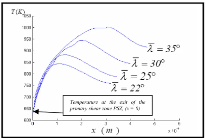
The effect of the global friction coefficient
( )
tan
µ= λ on the temperature distribution is reported in Fig 3 and in Tab 1. It shown, that the global friction has a significant effect on the length " of the sticking zone. An increase of
"
a
λ leads to an increase of the local friction coefficient µ at the sliding zone, which inturn sl
increases the temperature at the tool-chip interface.
Temperature at the exit of the primary shear zone PSZ, (x = 0)
Figure 3 : Effect of the global friction coefficient
( )
tan
µ= λ on the temperature distribution at the tool chip interface.
Tab 2,
ha our on the thermo-mechanical conditions f friction at the tool-chip interface through a parameter illustrates the influence of the workpiece material be vi
o
ν of the Johnson-Cook law; see equation (1), with 50 / and 25
V = m mn λ= ° .
The increase of the thermal softening induces a duction of the shear stress at the tool-chip interface. re
This produces an increase of the sticking zone and of the local friction coefficient µ in the sliding zone sl
The increase of the thermal softening of the machined material is equivalent to the reduction of the J-C law coefficient " "ν since th ratioe
(
T T T− r m−Tf)
is lessal nning coefficient than 1. Therm Softe " "ν Sticking zone c a Ratio= L Local friction coefficient sl µ 1.46 0.23 0.52 1 0.31 0.58 0.5 0.5 0.88
Tab 2: Influence of the thermal softening coefficient ν ,
on the sticking zone ratio and on the local friction µsl
odel is pres nical material flow in the prim chip contact length and the pr
[1] Shaw M.C. Metal Cutting Principles. Oxford ons, Oxford, 1984.
, Ferguson W.G. The temperature Magazine, [3]
ormation. Proc. R. Soc. [4] [5] ovative Tool-Chip rmation during [6] [7] nary shear Phys. Solids,, [9]
Trans. ASME J. Engineering [11]
1997.
Tab 1 uence of t obal friction fficient
4. C
ONCLUSIONS:
In this work , a hybrid Analytical-Numerical m ented. The thermomecha
ary shear zone, the
tool-essure at the tool-chip interface are obtained from an analytical approach. Besides, the non linear thermal
problem in the chip is solved by finite elements method. The sticking-sliding zones (i.e. the secondary shear zone) are taken into account by considering a simple model of the velocity distribution in the chip. Note that the model can be used with any kind of the distribution of the flowing speed of chip material. The present approach can be used to analyse, the effects of cutting process on the frictional conditions at the tool-chip interface wich affect directly the tool wear.
REFERENCES
Global friction angle λ Sticking zone c a Ratio= L Local friction coefficient sl µ 22° 0.13 0.42 25° 0.23 0.52 30° 0.4 0.85 Science Publicati [2] Campbell J.D 35° 0.58 1.72and strain rate dependence of the shear strength of mild steel. Philosophical
: infl he gl coe
( )
1970. 21: p. 63-82.Doyle E.D, Horne J.G, Tabor D. Frictional Interactions between chip and rake face in continuous Chip F
tan
µ= λ on the sticking zone and on the local friction coefficient µsl
London, Ser. A.366,, 1979: p. 173-187. Trent E.M, Metal cutting. Editions Butterworths, Londres, 1984.
M'Saoubi R, Chandrasekaran H. Inn Methods for the Investigation of Adhesion and Layer Fo
Machining. CIRP Annals - Manufacturing Technology, 2005. 54(1): p. 59-62.
Zorev N.N, Massey H.S.H. Metal Cutting Mechanics. Pergamon Press, 1966.
Molinari A, Dudzinski D. Statio
band in high-speed machining. C.R. Acad. Sci, Paris, 1992. 315 (II): p. 399-405.
[8] Moufki A, Molinari A, Dudzinski D. Modelling of orthogonal cutting with a temperature dependent friction law. J. Mech.
1998. 46(No. 10): p. 2103-2138.
Usui E, Takeyama H. A photoelastic analysis of machining stresses,. ASME J. Eng. Ind. 82, 1960: p. 683-688.
[10] Kato S, Yamaguchi K, Yamada M. Stress distribution at the interface between tool and chip in machining.
Ind., 1972. 94: p. 683-689.
Molinari A, Moufki A, Dudzinski D. Etude du comportement du 42CD4. Final Technical Report, CREAS Ascometal,
![Figure 1 : model of the primary shear band [8]. The contact length, the rake angle, the undeformed chip thickness and the chip thickness are denoted respectively by L c , α, t 1 , and t 2](https://thumb-eu.123doks.com/thumbv2/123doknet/7304950.209448/3.892.461.801.118.253/figure-primary-contact-undeformed-thickness-thickness-denoted-respectively.webp)