HAL Id: tel-01147076
https://pastel.archives-ouvertes.fr/tel-01147076
Submitted on 29 Apr 2015
HAL is a multi-disciplinary open access
archive for the deposit and dissemination of sci-entific research documents, whether they are pub-lished or not. The documents may come from teaching and research institutions in France or abroad, or from public or private research centers.
L’archive ouverte pluridisciplinaire HAL, est destinée au dépôt et à la diffusion de documents scientifiques de niveau recherche, publiés ou non, émanant des établissements d’enseignement et de recherche français ou étrangers, des laboratoires publics ou privés.
en phase conceptuelle appliquée aux projets de
construction
Cyril Mauger
To cite this version:
Cyril Mauger. Méthode de conception de produit intégrant ses services en phase conceptuelle appliquée aux projets de construction. Autre. Ecole nationale supérieure d’arts et métiers - ENSAM, 2014. Français. �NNT : 2014ENAM0046�. �tel-01147076�
Arts et Métiers ParisTech - Centre de Metz Laboratoire Conception Fabrication Commande
2014‐ENAM‐0046
École doctorale n° 432 : Sciences des Métiers de l’Ingénieur
Doctorat ParisTech
T H È S E
pour obtenir le grade de docteur délivré par
l’École Nationale Supérieure d'Arts et Métiers
Spécialité “Conception”
présentée et soutenue publiquement parCyril MAUGER
le 19 décembre 2014Framework for Integration of Services in Product
Requirements Definition Applied to Public Buildings
Directeur de thèse : Jean-Yves DANTAN Co-encadrement de la thèse : Éric DUBOIS, Ali SIADAT
Jury
Mme Lucienne BLESSING, Professeur, RUES, University of Luxembourg (LU) Présidente M. Benachir MEDJDOUB, Professeur, CVTR Lab, Nottingham Trent University (GB) Rapporteur M. Jean-François BOUJUT, Professeur, G-SCOP, Grenoble INP (FR) Rapporteur M. Roel WIERINGA, Professeur, CTIT, University of Twente (NL) Rapporteur M. François VERNADAT, HDR, Cours des Comptes Européennes (LU) Examinateur M. Jean-Yves DANTAN, Professeur, LCFC, Arts et Métiers ParisTech (FR) Examinateur M. Eric DUBOIS, Professeur, Université de Namur (BE) Examinateur M. Ali SIADAT, Maitre de Conférences, LCFC, Arts et Métiers ParisTech (FR) Examinateur M. Sylvain KUBICKI, Docteur, SSI, CRP Henri Tudor (LU) Invité M. Christophe GOBIN, Docteur, Vinci Construction France (FR) Invité
T
H
È
S
E
‘‘Le plus grand obstacle à la vie est l’attente, qui espère demain et néglige aujourd’hui.’’ – Sénèque, De la brièveté de la vie
i
To all my teachers, who fed me with their knowledge for so many years without any proper feedback or
gratefulness. Their altruism is exemplar and too often neglected by their students.
iii
First and foremost, I would like to thank the Fond National de la Recherche (FNR) Luxembourg for funding this research project through the Aide à la Formation Recherche (AFR) grant scheme dedicated to PhD research project. This thesis would have been impossible without their support. I am also grateful to the Public Research Centre Henri Tudor for hosting me during these nearly five years and for providing me with appropriate equipment and resources. Together with the Laboratoire Conception Fabrication Commande of Arts et Métiers ParisTech, they properly completed the FNR support.
I would like to thank the members of jury of my thesis for their time, effort, and consideration. I warmly thank Professor Lucienne BLESSING, not only for “accepting” to be the President of my jury but also for her wise advices and feedbacks on various occasions along these four years. It really meant something to me to have you at my Viva, as a closure. I would like to thank Professor Jean-François BOUJUT, Professor Benachir MEDJDOUB, and Professor Roel WIERINGA for accepting to be the reviewers of my dissertation. Their interesting and detailed reviews provided me great confidence to prepare my defence. I am grateful to Dr François VERNADAT and Dr Christophe GOBIN who kindly accepted to be part of that great jury in charge of judging the results of my research. It was an honour to be assessed by all of you regarding your respective domain of expertise.
I am heartedly thankful to my 4 supervisors for their patience, understanding and support. I cannot say how long it took us to be able to understand each other (or rather to understand me). This was quite a challenge but we managed it together. I am indebted to my main supervisor, Professor Jean-Yves DANTAN, who provided me with guidance when I was lost, support when I was alone, and advices when I was confused. I am thankful to Dr Ali SIADAT, second supervisor from Arts et Métiers ParisTech, for all the professional and personal discussions, for his availability and encouragements. Being my Master Thesis supervisors, I spent more than five years with the two of them. They unconditionally supported my way of thinking, my ideas, and me. There would not have been any thesis without you, the first ones who really believed in me.
My sincerest gratitude also goes to my two co-supervisors from Henri Tudor who joined the team for the PhD: Professor Eric DUBOIS for his high interest and trust about the topic, for the insights from Software Engineering, and for having naturally shared his scientific network; and Dr Sylvain KUBICKI for his commitment on this new topic not only during but also after the PhD, for his expertise on AEC issues on which I still have a lot to learn from him, and for his more than welcome critical feedbacks. Your additional support and expertise were essential to the success of this project.
I warmly thank Professor Daniel BERRY for his commitment and interest, for the precious case study and advices that helped me go through the PhD, and for his cheerful support. We met at the right time, when things got more difficult for me; you pushed me further and were an unexpected source of motivation for me. I am indebted to my friend Dr Ahmed Jawad QURESHI for sharing his knowledge and network with me, for all the discussions we had, and most importantly for his friendship. You did a lot to help me behind the scene, and I am utterly grateful to you for that. I also thank Dr Alain ETIENNE for his time and expertise on the matters of database and metamodeling. I am grateful to Mr André RIFAUT for all the discussions, references and advices regarding GORE.
This research would not have been a success without interesting case studies. I express my gratitude to Messrs Thomas SCHWARTZ and Lahcène HARBOUCHE for accepting to take me as a Master Thesis trainee to work on the Luxembourgish secondary school project which became later my first case study. The initiation of this PhD project would not have been possible without their support. I address my special thanks to my uncle, Mr René MAUGER, for his support by introducing me to the city council of Betton which led me to my second case study: the multimedia library in France. I would like to thank the persons from the city council of Betton: its
iv
mayor, Mr Michel GAUTIER, for accepting to let me use the information about the multimedia library; Messrs Michael PIOLAIN and Patrice VALLEE as well as the head of the multimedia library, Mrs Muriel PIFFETEAU, for their time and all the documents on the case study. I also thank Professor Daniel BERRY and the rabbi from the Canadian synagogue kitchen case study, third case study of this thesis. I would like to thank the Fonds Belval for accepting to let me use the University Library of Luxembourg as a fourth case study, as well as Mrs Marie-Pierre PAUSCH-ANTOINE and Mrs Julie WILLEMS from the University Library for their time, inputs and feedbacks.
I would like to thank all the AEC professionals for their time, interest about, and feedbacks on my research: Mr Matthieu BOURDON; Messrs Serge VANNEYRE, Alain GRANDJEAN, and all the other trainers from the GEPA PAMO training; as well as Vinci Construction France, Polaris Architect and Schroeder & Associés for their support on the topic before the FNR. I also thank Dr Sepideh GHANAVATI, Mrs Margot HARTMAN, Mrs Anja DUMJAHN and the other secretaries from Tudor for the proofreading of this thesis.
I express my gratitude to all my colleagues and friends who provided me with technical, logistical, and moral support along these 4 to 5 years spent between Metz and Luxembourg: Jean-Baptiste, Jinna and Renaud during my stays in Metz; Kiki & Clémence and Bubu & Marianne (+ Eva) during my stays in Paris; Hervé & Olivier for the essential daily coffee breaks; Alek, Alex(s), Amandine, Amir, Annie, Antoine(s), Bruno, Céline, David, Dong, Edwin, Georgios, Hella, Muriel, Pierre, Simon(s), Younes, Yves, Zak… and all the others I forgot to mention in here for your participation in making this journey less difficult (almost pleasant) to complete.
Finally, I am grateful to my parents, Odile & Patrick, my brothers, Xavier & Bastien, and all my (growing) family for their constant support and encouragement despite the distance that never stopped to increase each year since I left Brittany. The distance might continue to increase in the next years but I will never stop to love you for what you have done with me. Last but not least, I would like to thank my cat Grumpfeth for its constant effort to distract me from finishing this damn PhD (it did a great job to promote procrastination with a few other folks). Without it, I might have finished earlier but without comfort. Adopting it was the best thing I did to slow down a little bit, just enough to start to really enjoy the journey.
v
This PhD research project takes its roots in the master thesis performed by the applicant on “adapting conceptual design methods to construction projects” in 2010. The first objective was to
analyse and compare Value Management, the APTE® method, Quality Function Deployment
(QFD), and Requirements Engineering regarding the architectural programming of Architecture-Engineering-Construction projects. This project was developed side-by-side with a real architectural programming case study: the refurbishment and extension of a secondary school in Luxembourg, the Lycée Technique de Bonnevoie (LTB). Based on the first encouraging results, a PhD grant application was successfully accepted to deepen the research and it gave birth to the following research topic.
The National Research Fund of Luxembourg financed the present project under the AFR grant scheme (Aides à la Formation-Recherche). The application ID is 1000660 associated to the AFR-PhD 2010-2 call for proposals. The original grant covered three years of research from February 2011 to January 2014 with an agreed extension for a fourth year from February to October 2014.
The PhD research project broadens the original scope by aiming to identify trails for the improvement of architectural programming practices through knowledge transfer from engineering domains such as Mechanical Engineering, Software Engineering and Industrial Engineering to Architecture-Engineering-Construction domain. These improvements mainly concern functional requirements definition of public construction projects. Proof of concepts on either post ex facto or current case studies are used to validate those trails. The development of a demonstrator is out of this research scope but part of the research perspectives.
Identified trails constitute a research roadmap to deepen with more qualified experts, professionals, and partners from the required domains on a higher scale. This research project is the first initiative leaded by both the Service Science and Innovation (SSI) department of Public Research Centre Henri Tudor and the Laboratoire Conception Fabrication Commande (LCFC) of Arts et Métiers ParisTech on the architectural programming topic. The major challenge of this project is to develop a multi-disciplinary approach which takes into account the services provided by the building during its conceptual design. This objective will be achieved by the adaptation and the development of a framework based on the interoperability of multi-disciplinary approaches.
The SSI department hosts the following domains of expertise: Software Engineering (e.g. Goal-oriented Requirements Engineering) and Architecture-Engineering-Construction (e.g. ICT, CAD, and BIM). The LCFC hosts the following domains of expertise: Mechanical Engineering (e.g. conceptual design) and Industrial Engineering (e.g. Enterprise Architecture, information systems). Each domain of expertise is represented by one person in the supervision team:
Pr. Jean-Yves DANTAN, lead supervisor: Mechanical Engineering Pr. Eric DUBOIS, research advisor: Software Engineering
Dr. Ali SIADAT, research advisor: Industrial Engineering
Dr. Sylvain KUBICKI, research advisor: Architecture-Engineering-Construction The applicant has a general engineering background with major knowledge in Mechanical Engineering and Industrial Engineering. A professional training was taken in architectural programming at the very beginning of the research project to fill the gap of knowledge on the topic of interest. These are all the ingredients gathered in this research project to provide an original and innovative research and practical contribution.
To comply with the requirements of the European Doctorate Label, the following document was written in English, and the defence was performed in English with a Jury composed of a European committee. A substantial abstract in French completes this document in agreement with the Toubon Law (Loi n°94-665 du 4 août 1994 relative à l’emploi de la langue française).
vii Referred Conference Papers
1. Mauger, C., Schwartz, T., Dantan, J.-Y., and Harbouche, L., 2010. Improving users
satisfaction by using requirements engineering approaches in the conceptual phase of construction projects: The elicitation process, in 2010 IEEE International Conference on Industrial Engineering and Engineering Management (IEEM), IEEE, pp. 310–314.
2. Mauger, C., and Kubicki, S., 2013. A Conceptual Model for Building Requirements
Processing, in Proceedings of the 11th International Post-Graduate Research Conference (IPGRC), University of Salford, UK, pp. 318–330.
3. Mauger, C., 2013. A Design Artifact for Functional Assessment of Construction Projects,
in Hadju, M. and Skibniewski, M. eds., Proceedings of the Creative Construction Conference 2013, 6-9 July 2013, Budapest, Hungary, pp. 505–515.
4. Mauger, C., and Dantan, J.-Y., 2013. Buildings Definition as Product-Service Systems, in
Proceedings of the Congrès Français de Mécanique 2013, August 26-30th 2013, Bordeaux, France, Bordeaux, France, pp. 1–6.
5. Mauger, C., Dantan, J.-Y., and Dubois, E., 2014. GFBS : A PSS Design Model Applied to
the Briefing Process of Construction Projects, in Marjanović, D., Storga, M., Pavkovic, N., and Bojcetic, N. eds., Proceedings of the International Design Conference - Design 2014, Dubrovnik, Croatia, May 19-22 2014, Faculty of Mechanical Engineering and Naval Architecture, University of Zagreb, The Design Society, Glasgow, pp. 905–914.
6. Mauger, C., and Berry, D.M., 2014. Lessons Learned from and for Requirements
Engineering and Building Construction : A Case Study of Requirements Engineering for a Synagogue Kitchen with Use Cases and Scenarios, in Proceedings of the Software Summit SwSTE 2014 The IEEE Computer Society International Software Conference, 11-12 June 2014, Tel-Aviv, Israel, IEEE Computer Society CPS, pp. 67–76.
7. Mauger, C., and Kubicki, S., 2014. Intégration de la notion de Service dans un processus
de modélisation adapté à la programmation architecturale, in Kubicki, S., Halin, G., and Bignon, J.-C. eds., Proceedings of the Séminaire de Conception Architecturale Numérique (SCAN’14), 18-20 Juin 2014, Luxembourg, PUN - Editions Universitaire de Lorraine, pp. 125–135.
Poster Session
1. Mauger, C., and Berry, D.M., 2013. Requirements Engineering and Building
Construction : Requirements Engineering for a Synagogue Kitchen with Use Cases and Scenarios, in Poster session REFSQ2013, pp. 15.
Doctoral Symposium
1. Mauger, C., 2012. Method for the conceptual phase of an Integrated Product and Service
Design applied to Construction Project, in Dörr, J., Fricker, S., and Paech, B. eds., Proceedings Requirements Engineering: Foundation for Software Quality - 18th International Working Conference (REFSQ 2012), Volume 2 - Workshops, Doctoral Symposium, Empirical Track, Essen, Germany, pp. 365–372.
ix
Dedication ... i
Acknowledgements ... iii
Preface ... v
Publications Arising from the Research ... vii
Table of Contents ... ix
List of Figures ... xv
List of Tables ... xix
List of Appendices ... xxi
Acronyms & Abbreviations ... xxiii
Part A – Résumé Etendu en Français ... 1
Chapitre I – Contexte... 3
1. Introduction ... 3
1.1. La Programmation Architecturale ... 3
1.2. Spécificités des Projets de Construction ... 3
1.3. Etat de l’Art ... 4 1.4. Synthèse ... 5 2. Objectifs ... 5 2.1. Objectifs Industriels ... 5 2.2. Objectif Scientifique ... 6 2.3. Synthèse ... 7 3. Méthodologie ... 8
3.1. Sciences de la Conception et Recherche en Conception ... 8
3.2. Cas d’Etudes ... 8
3.3. Transdisciplinarité ... 9
4. Plan du Résumé Etendu ... 9
Chapitre II – Décrire un Bâtiment ... 11
1. Introduction ... 11
2. Développement de Systèmes : Vue d’Ensemble Multidisciplinaire ... 12
3. Clarification des Concepts ... 13
3.1. But – Pourquoi ... 13
3.2. Fonction – Quoi ... 13
3.3. Activité – Comment et Quand ... 14
3.4. Ressource – Qui/Avec Quoi ... 15
3.5. Espace – Où ... 16
3.6. Domaine de Définition ... 17
4. Synthèse ... 17
Chapitre III – Modéliser un Bâtiment ... 19
1. Introduction ... 19
2. Modéliser l’Objet d’Etude : Le Bâtiment en tant que Système ... 19
x
2.2. Paradigme Système Produit-Service ... 21
2.3. Principe d’Alignement ... 22
2.4. En Résumé ... 22
3. Un Modèle pour la Programmation Architecturale ... 23
4. Modèles Opérationnels pour une Formalisation Pratique Multi-Vue ... 24
5. Du Programme au Projet : Le Concept de Méta-Espace ... 26
6. Modèle Transitoire : Le Diagramme de Méta-Espace ... 27
7. Synthèse ... 28
Chapitre IV – Définir un Bâtiment ... 29
1. Introduction ... 29
2. GFBS appliqué à la Définition des Besoins ... 30
2.1. Identification de l’Environnement (étape 0) ... 30
2.2. Définition du But (étape 1) ... 30
2.3. Génération de Fonctions (étape 2)... 30
2.4. Allocation des Fonctions (étape 3 et 4) ... 30
2.5. Décomposition des Comportements (étape 5) ... 31
2.6. Traitement des Exigences (étape 6) ... 31
2.7. Synthèse Fonctionnelle (étape 7) ... 31
2.8. Synthèse Physique (étape 8) ... 31
2.9. En Résumé ... 31
3. Instanciation sur des Vues Processus ... 31
3.1. Vue Processus ... 32
3.2. Vue Information ... 32
3.3. Vue Collaboration ... 33
3.4. En Résumé ... 33
4. GFBS appliqué à l’Evaluation de Projets ... 33
4.1. Analyse Fonctionnelle ... 34 4.2. Evaluation Fonctionnelle... 34 4.3. Evaluation Quantitative ... 34 4.4. En Résumé ... 34 5. Synthèse ... 35 Chapitre V – Conclusion ... 37 1. Synthèse Scientifique ... 37 2. Synthèse Industrielle ... 37
Part B – English Full Version ... 39
Chapter I – Background ... 41
1. Introduction ... 42
1.1. Definition ... 42
1.2. Construction Project Specificities ... 43
1.3. State of Art and Issues ... 44
1.4. Synthesis ... 50
xi
2.3. Main Goal ... 52
2.4. Industrial Objectives ... 52
2.5. Synthesis ... 52
3. Research Objective and Questions ... 53
3.1. Research Problem Statement... 53
3.2. Research Objective & Questions ... 54
3.3. Synthesis ... 54
4. Methodology ... 54
4.1. Data Collection ... 55
4.2. A Design Science Framework ... 55
4.3. A Design Research Methodology ... 56
4.4. Case Studies ... 57
4.5. Transdisciplinary Research ... 60
5. Layout of the dissertation ... 61
Chapter II – Describe a Building ... 63
1. Introduction ... 64
1.1. Clarification of RQ1... 64
1.2. Literature Review ... 64
1.3. Methodological Conclusion ... 65
2. Multidisciplinary Overview of System Development Processes ... 65
3. Concepts Clarification ... 70
3.1. Goal – Why ... 70
3.2. Function – What ... 73
3.3. Activity – How & When ... 77
3.4. Resource – Who ... 79
3.5. Space – Where ... 82
3.6. Definition Domain ... 84
4. Synthesis ... 84
Chapter III – Model a Building and its Definition Domain ... 87
1. Introduction ... 88
2. Modelling the Object of Study: Building as a System ... 88
2.1. Systemic ... 89
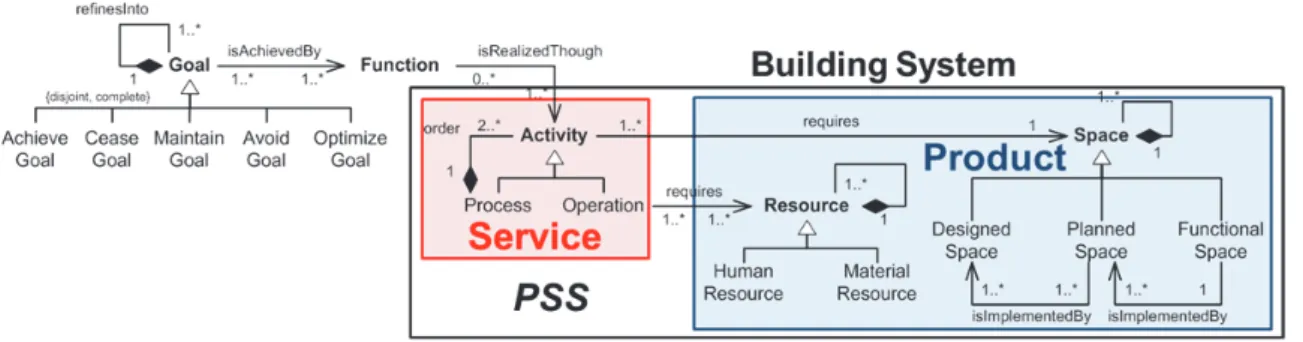
2.2. Building as a Product-Service System ... 93
2.3. Alignment Concept ... 99
2.4. In Summary ... 99
3. A Model for Architectural Programming ... 100
3.1. Models from Design Theory ... 100
3.2. FBS ... 101
3.3. GFBS Constructs ... 103
xii
3.5. In Summary ... 106
4. Operational Models for a Multi-View Practical Formalisation ... 107
4.1. Goal ... 107
4.2. Function ... 109
4.3. Behaviour ... 111
4.4. Structure ... 115
4.5. Bridging Operational Models Together ... 122
4.6. In Summary ... 123
5. From the brief to the design proposal ... 124
5.1. Meta-Space – Principle ... 125
5.2. Meta-Space – A Taxonomy ... 126
5.3. Conclusion ... 127
6. Meta-Space Diagram – An Intermediary Transition Model ... 128
6.1. Meta-Space Diagram ... 128
6.2. Operational Meta-Space Diagram ... 129
6.3. Functional Meta-Space Diagram ... 131
6.4. Design Meta-Space Diagram ... 133
6.5. In Summary ... 134
7. Synthesis ... 134
Chapter IV – Define a Building ... 137
1. Introduction ... 138
2. GFBS Briefing Framework ... 139
2.1. Environment Identification (Step 0) ... 141
2.2. Goal Definition (Step 1) ... 143
2.3. Function Generation (Step 2) ... 145
2.4. Functional Allocation (Steps 3 & 4) ... 147
2.5. Behavioural Refinement (Step 5) ... 148
2.6. Processing (Step 6) ... 150
2.7. Functional Synthesis (Step 7) ... 152
2.8. Physical Synthesis (Step 8) ... 154
2.9. In Summary ... 155
3. GFBS Process Model Views ... 156
3.1. Process Model View ... 156
3.2. Information Flow Process Model View ... 160
3.3. Collaborative Model View ... 163
3.4. In Summary ... 165 4. GFBS Assessment Framework ... 165 4.1. Functional Analysis ... 167 4.2. Functional Assessment ... 170 4.3. Quantitative Assessment ... 173 4.4. In Summary ... 174 5. Synthesis ... 174
xiii
1.1. Research Problem ... 178
1.2. Research Questions & Contributions ... 178
1.3. Research Perspectives ... 179
2. Industrial Synthesis ... 180
2.1. Industrial Goal ... 180
2.2. Industrial Objectives ... 180
2.3. Research Transfer to Industry ... 181
2.4. Industrial Perspectives ... 182
References ... 183
xv
Figure 1 – Conceptual phase of construction projects: architectural programming (adapted from (Macmillan et al. 2001)) ...42
Figure 2 – Evolution of costs and savings along construction projects development based on (Certu 2010; Faatz 2009) ...43
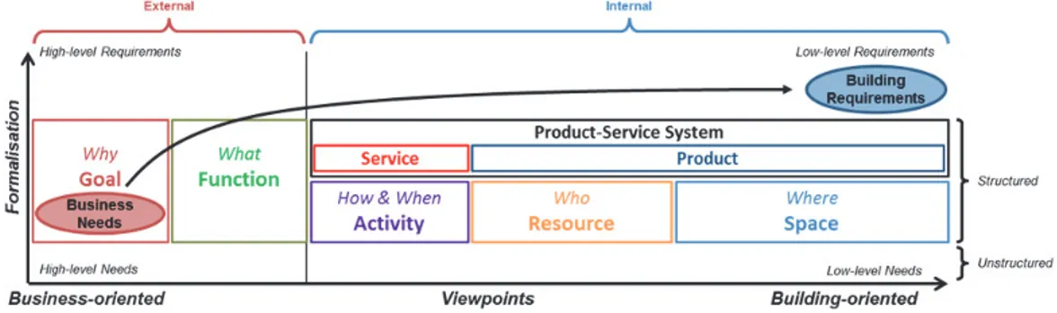
Figure 3 – From Paying Clients’ Business Needs to User and Customer Clients’ Building Requirements ...50
Figure 4 – Conceptualization of the seven focused issues of this research ...51
Figure 5 – Representation of the Transition from Business Needs to Building Requirements regarding the Current Situation ...53
Figure 6 – Illustration of the Research Objective ...54
Figure 7 – DRM framework adapted from (Blessing & Chakrabarti 2009) ...57
Figure 8 – Sources of Information for Each Case Study ...58
Figure 9 – Information Coverage Synthesis of Case Studies ...59
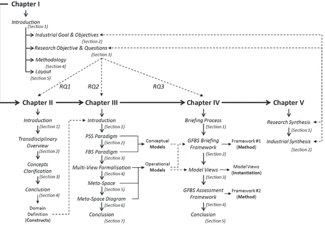
Figure 10 – Dissertation Layout & Relationships between Sections ...62
Figure 11 – Graphical Convention used in Chapter II ...63
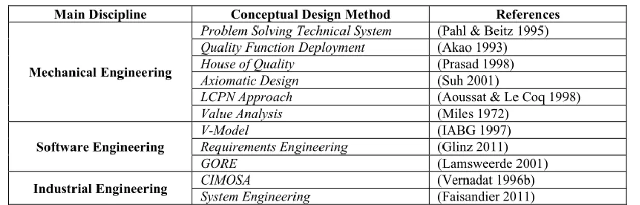
Figure 12 – Positioning of the Concepts used by Conceptual Design Methods to Describe a System (Appendix A) ...66
Figure 13 – Concepts used in Various Conceptual Design Methods across Engineering ...67
Figure 14 – Three Analysis Phases of Conceptual Design Methods ...68
Figure 15 – Deliverables that Punctuate the Conceptual Design Methods ...68
Figure 16 – Positioning of the Six Interrogatives from Conceptual Design ...69
Figure 17 – Main Concepts from the Multidisciplinary Overview ...69
Figure 18 – Conceptual Model of the Goals Refinement-Abstraction ...71
Figure 19 – Conceptual Model of the Goal Concept in GORE ...72
Figure 20 – Conceptualization of Gobin’s proposal ...74
Figure 21 – Illustration of the Function Concept on the LTB Case Study ...76
Figure 22 – Conceptual Model of the Goal–Function Relationship ...77
Figure 23 – Synthesis Conceptual Model of the Activity Concept in System and Software Engineering ...78
Figure 24 – Conceptual model of the Activity concept based on (Vernadat 1996b; Vernadat 1996a) ...78
Figure 25 – Conceptual Model of the Activity Concept ...79
Figure 26 – Resulting Conceptual Model of the Goal, Function, and Activity Concepts ...79
Figure 27 – Conceptual Model of the Resource Concept from IFC viewpoint ...80
Figure 28 – Conceptual Model of the Activity–Resource Relationship ...81
Figure 29 – Conceptual Model of the Space Concept ...82
Figure 30 – Conceptual Model of the Activity-Space Relationship ...84
Figure 31 – The six interrogatives and their key concepts for Architectural Programming ...84
Figure 32 – Structuration of the Definition Domain Viewpoints ...85
Figure 33 – Plan of Chapter III ...87
Figure 34 – System as a black box...90
Figure 35 – System as a white box ...91
Figure 36 – Scope of the studied system illustrated on the school building example ...91
Figure 37 – Conceptual model of the System concept ...92
Figure 38 – Analysis of the former building plan view from above ...94
Figure 39 – Main and subcategories of PSS from (Tukker 2004) ...95
Figure 40 – Taxonomy of Services ...97
Figure 41 – PSS: First level of conceptual formalisation ...98
Figure 42 – Representation of the Coverage of PSS parts on the Defined Constructs ... 100
Figure 43 – Gero’s FBS framework from (Gero 1990) to (Gero & Kannengiesser 2004) ... 102
Figure 44 – Illustration of the Relationship between Goal and Function ... 103
Figure 45 – Conceptual model of the Behaviour modelling construct ... 104
Figure 46 – Conceptual model of the Structure modelling construct ... 104
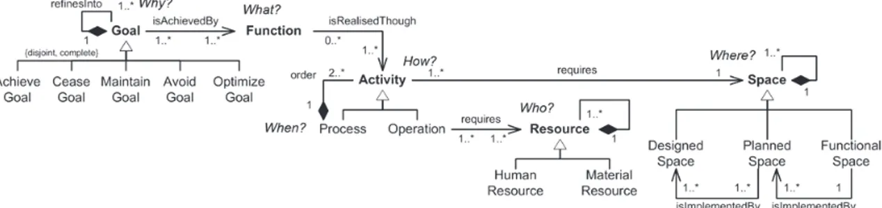
Figure 47 – Conceptual model of the GFBS modelling constructs ... 105
Figure 48 – GFBS conceptual model for PSS ... 105
Figure 49 – Illustration of the continuity between GFBS and FBS conceptual models ... 106
Figure 50 – GFBS: Second level of conceptual formalisation ... 107
Figure 51 – Different GORE notations to model constructs ... 108
Figure 52 – Estimation of RE coverage by main GORE Techniques based on (Giunchiglia et al. 2001; Lapouchnian 2005) ... 108
Figure 53 – Formalisation Coverage of GORE modelling languages ... 109
Figure 54 – Principle and convention of the interaction diagram ... 110
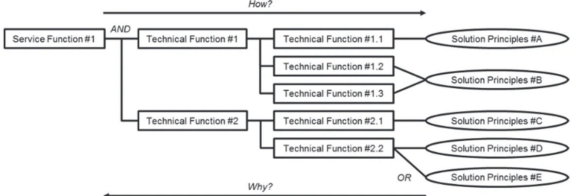
Figure 55 – Principle and convention of the Function-Means Tree ... 110
Figure 56 – Principle and conventions of the FAST diagram ... 110
Figure 57 – Principle and convention of the Function Block Diagram ... 111
Figure 58 – Formalisation Coverage of Functional models ... 111
Figure 59 – Principle and convention of IDEF0/SADT ... 112
Figure 60 – Difference between the main Business Process Diagrams (OMG 2011a) ... 113
Figure 61 – UML 2.4 Taxonomy of Structure and Behaviour Diagram (OMG 2011b) ... 114
Figure 62 – Main UML Behaviour Diagrams: Principle and Convention ... 114
Figure 63 – Formalisation Coverage of Behaviour models ... 115
Figure 64 – Principle and Convention of the Class Diagram ... 115
Figure 65 – Principle and Convention of the Object Diagram ... 116
Figure 66 – Principle and Convention of the Entity-Relationship Diagram ... 116
Figure 67 – Principle and Convention of a Product Breakdown Structure ... 116
Figure 68 – Formalisation Coverage of Resource models ... 117
Figure 69 – Simplified functional diagram based on a multimedia library brief (Aubry & Guiguet Programmation, 2003) ... 117
Figure 70 – One functional diagram, three design proposal ... 118
Figure 71 – Two kinds of adjacency matrix ... 119
xvi
Figure 73 – From functional spaces in Venn diagram to physical spaces in Schematic Plan ... 120
Figure 74 – Bubble diagram vs. zoning diagram ... 120
Figure 75 – From a single briefing model to several design models ... 121
Figure 76 – Formalisation Coverage of Space models ... 121
Figure 77 – Operational Models Coverage of the Definition Domain ... 122
Figure 78 – Coverage of Model Viewpoints on the Conceptual Model of the Definition Domain ... 123
Figure 79 – Representation of Current Architectural Programming Definition Domain ... 123
Figure 80 – Missing Overlap in Operational Models Coverage of the Definition Domain ... 124
Figure 81 – Representation of information loss along the architectural programming from the clients’ needs to the architects’ plan .. 124
Figure 82 – Meta-Space principle illustrated on the book cycle ... 125
Figure 83 – Conceptual model of the Briefing Meta-Spaces ... 126
Figure 84 – Conceptual Model of the Design Meta-Spaces ... 127
Figure 85 – Conceptual Model of the Meta-Space Artefacts and Related Main Deliverable... 128
Figure 86 – Resulting Conceptual Model of the Building Definition Domain ... 128
Figure 87 – Meta-Space Diagram Principle illustrated on a limited part of the book cycle ... 129
Figure 88 – From needs toward proposals, positioning of the functional diagram (already introduced in Figure 81) ... 129
Figure 89 – Positioning of the Operational Meta-Space Diagram ... 129
Figure 90 – From IDEF0 model to Operational Meta-Space Diagram (cleaning activity in a kitchen) ... 130
Figure 91 – Quality of input-output flows during the cleaning activity ... 130
Figure 92 – From a BPMN functional model to an Operational Meta-Space Diagram ... 131
Figure 93 – Positioning of the Functional Meta-Space Diagram ... 131
Figure 94 – From operations to functional spaces using meta-spaces artefacts and diagrams ... 132
Figure 95 – From the complete Functional Diagram to the complete Functional Meta-Space Diagram with two different layouts based on the same content ... 132
Figure 96 – Positioning of the physical meta-space diagram ... 133
Figure 97 – Comparison of three architectural projects for the same brief (multimedia library) ... 133
Figure 98 – Meta-Space Diagrams Coverage of the Definition Domain ... 134
Figure 99 – Positioning of Chapter IV ... 137
Figure 100 – BPMN modelling of a briefing process ... 138
Figure 101 – IDM Building Programming process map from BuildingSmart (Jerving 2011) ... 139
Figure 102 – GFBS Briefing Framework ... 140
Figure 103 – Case Studies Coverage of the Framework ... 140
Figure 104 – Axiomatic Design refinement principle of the GFBS framework ... 140
Figure 105 – Environment identification ... 141
Figure 106 – Map of Betton positioning the community facilities and the multimedia library (2014) ... 142
Figure 107 – Local Urban Plan of Betton around the multimedia library ... 143
Figure 108 – Taxonomy of cultural documents that can be distributed in a multimedia library ... 143
Figure 109 – Goal definition ... 144
Figure 110 – “Horned beast” representing the main goal of the multimedia library ... 145
Figure 111 – Function Generation ... 145
Figure 112 – Interaction diagram based on Functional Analysis method ... 146
Figure 113 – Interaction diagram of the University Library based on the strategic brief ... 146
Figure 114 – Functions induction dependency ... 147
Figure 115 – Functional allocation ... 147
Figure 116 – Behavioural refinement ... 148
Figure 117 – State-Transition Diagram representing a person rights according to their status ... 149
Figure 118 – Partial illustration of UML diagrams applied on the kitchen case study ... 149
Figure 119 – Partial IDEF0 of the kitchen case study ... 150
Figure 120 – Requirements processing ... 150
Figure 121 – Requirements processing principle in two steps (already introduced in Chapter III Section 5.1 Figure 82) ... 151
Figure 122 – Partial BPMN of the book cycle in a multimedia library ... 151
Figure 123 – Operational Meta-Space Graph (6.2) of the partial BPMN ... 151
Figure 124 – Processing of the “Reception” Meta-Spaces (6.3) ... 152
Figure 125 – Functional synthesis ... 152
Figure 126 – From operational meta-space group to functional space ... 153
Figure 127 – Functional diagram of the multimedia library (reminder from Figure 69) ... 153
Figure 128 – Functional synthesis restricted to information about the book cycle (already introduced in Chapter III Section 6.3 Figure 94) ... 154
Figure 129 – Physical Synthesis ... 154
Figure 130 – BPMN process model view of the GFBS briefing ... 156
Figure 131 – Local process model view on External Analysis (Steps 0 to 2) ... 157
Figure 132 – Local process model view on Internal Analysis (Steps 3 to 5) ... 158
Figure 133 – Local process model view on the Requirements Processing (Step 6) ... 159
Figure 134 – Local process model view on the Requirements Synthesis (Steps 7 & 8) ... 160
Figure 135 – IDEF0 Process Model View of the GFBS Framework ... 161
Figure 136 – External Analysis Information View ... 161
Figure 137 – Internal Analysis Information View ... 162
Figure 138 – Requirements Processing Information View ... 162
Figure 139 – Requirements Synthesis Information View ... 163
Figure 140 – IDM representation of the briefing process integrating GFBS framework ... 164
Figure 141 – Sequence Diagram representing the Services integration in the briefing process ... 165
Figure 142 – GFBS Assessment Framework ... 166
Figure 143 – BPMN model of the GFBS Assessment Framework ... 166
Figure 144 – Case Studies Coverage of the GFBS Assessment Framework ... 166
xvii
Figure 149 – Functional Meta-Space Graph of the 1st floor of the University library (III & IV) ... 168
Figure 150 – Modelling of the shelf spaces of the University library ... 168
Figure 151 – Meshing and modelling of a storage space, each bubble represents 1 m²; white bubbles represent circulation spaces whereas grey bubbles represent storage spaces ... 169
Figure 152 – Functional Analysis 2 ... 169
Figure 153 – Functional Analysis of the project A from the multimedia library... 169
Figure 154 – Two Scales of Functional Assessment ... 170
Figure 155 – Global Functional Assessment ... 170
Figure 156 – Comparison between the Functional Meta-Space Graph and the Functional Meta-Space Diagram ... 171
Figure 157 – Comparison of architectural projects based on the same functional diagram ... 171
Figure 158 – Local Functional Assessment ... 172
Figure 159 – Illustration of the “borrow and return” loop from the book cycle on the University library case study ... 173
Figure 160 – Quantitative Assessment ... 173
xix
Table 1 – Main U.S. pioneers of architectural programming, taken from (Cherry 1999) ...45
Table 2 – List of ICT solutions supporting architectural programming ...49
Table 3 – Design Science Framework (March & Smith 1995) ...56
Table 4 – Dissertation Layout & Design Artefacts Synthesis ...62
Table 5 – Corpus of Conceptual Design Methods Analysed ...66
Table 6 – Corpus of Analysed and Positioned AEC Architectural Programming Methods ...66
Table 7 – Examples of goals from the LTB Case Study ...72
Table 8 – Seven usage functions referential (Gobin 2003) ...74
Table 9 – Two different languages to talk about Space (Dursun 2009) ...83
Table 10 – Research Output of Chapter II: the Definition Domain ...85
Table 11 – Overview of prominent differences between Product and Service (Moritz 2005) ...95
Table 12 – Example of Products and Services based on the LTB Case Study ...98
Table 13 – Evolution of the FBS concept definitions ... 102
Table 14 – Research Output of Chapter III: Conceptual and Operational Models ... 135
Table 15 – Requirements elicitation techniques (Coulin 2007) ... 141
Table 16 – Functional table related to the University Library based on the strategic brief ... 146
Table 17 – Space Table of the Multimedia Library ... 155
Table 18 – Research Output of Chapter IV 1/2 ... 156
xxi
Appendix A – Concepts used in Various Conceptual Design Methods across Engineering (Figure 13) ... 201
Appendix B – Summary of the Proposed Definitions ... 203
Appendix C – List of Conceptual Models and their References ... 205
Appendix D – One Functional Diagram, Three Design Proposals (Figure 70) ... 211
Appendix E – Operational Models Coverage of the Definition Domain (Figure 77) ... 213
Appendix F – Resulting Conceptual Model of the Building Definition Domain (Restructured Figure 86) ... 215
Appendix G – Meta-Space Diagrams Coverage of the Definition Domain (Figure 98) ... 217
Appendix H – BPMN process model view of the GFBS briefing (Figure 130) ... 219
Appendix I – Detailed IDEF0 Process Model View of the GFBS Framework ... 221
Appendix J – University Library of Luxembourg Case Study: Allocation of Book Collections in the Future Building ... 223
xxiii AEC Architecture-Engineering-Construction
AFR Aide à la Formation Recherche
AIA American Institute of Architects
APICS American Production and Inventory Control Society
AQC Agence Qualité Construction
BIM Building Information Modelling
BPMN Business Process Modelling Notation
CAD Computer-Aided Design
CERTU Centre d’Etudes sur les Réseaux, les Transports, l’Urbanisme, et les constructions publiques
CRP Centre de Recherche Public
CRS Clients Requirements Specification
DGUHC Direction Générale de l'Urbanisme, de l'Habitat et de la Construction
DRM Design Research Methodology
DRS Design Requirements Specification
DS Descriptive Study
FAST Function Analysis System Technique
FBD Function Block Diagram
FBS Function Behaviour Structure
FFB Fédération Française du Bâtiment
FRS Functional Requirements Specification
GEPA Groupe pour l’Education Permanente des Architectes
GFBS Goal Function Behaviour Structure
GORE Goal-Oriented Requirements Engineering
ICT Information and Communication Technology
IDEF0 Integration DEFinition
IE Industrial Engineering
IEEE Institute of Electrical and Electronics Engineers
IFC Industry Foundation Classes
ISO International Standard Organisation
ITIL Information Technology Infrastructure Library
JORF Journal Officiel de la République Française
KAOS Knowledge Acquisition in automated specification or Keep All Objectives Satisfied
LCFC Laboratoire de Conception, Fabrication et Commande
LTB Lycée Technique de Bonnevoie
ME Mechanical Engineering
MIQCP Mission Interministérielle pour la Qualité des Constructions Publiques
MOA Maitrise d’Ouvrage (i.e. paying client)
MOE Maitrise d’Œuvre (i.e. design team)
NASA National Aeronautics and Space Administration
PAMO Programmation Architecturale Assistance à Maîtrise d’Ouvrage (professional training)
PBS Product Breakdown Structure
PRS Production Requirements Specification
PS Prescriptive Study
PSS Product-Service System
QFD Quality Function Deployment
RC Research Clarification
RIBA Royal Institute of British Architects
SADT Structured Analysis and Design Technique
SE Software Engineering
SoPSS Service-oriented Product-Service System
SPOS Service de Psychologie et d’Orientation Scolaire
SSI Service Science & Innovation
SYPAA Syndicat des Programmistes en Architecture et en Aménagement
UK United Kingdom
UML Unified Modelling Language
3
Chapitre I – CONTEXTE
Ce premier chapitre introduit le contexte de quatre années de recherche sur le sujet de la programmation architecturale et de la définition des besoins en ingénierie. La Section 1 définit, positionne et analyse la programmation architecturale en tant que sujet de recherche. La Section 2 introduit les objectifs industriels et scientifiques poursuivis tout au long de ces travaux. La Section 3 présente la méthodologie mise en place pour atteindre ces objectifs. Enfin, la Section 5 décrit l’organisation du résumé étendu.
1. Introduction
Le cycle de vie d’un bâtiment est composé d’activités complexes allant de l’idéation à la démolition. Chaque activité implique de nombreux acteurs hétérogènes sur une période de temps relativement courte. L’organisation de ces activités peut être multiple en fonction de différents critères (p. ex. type de bâtiment, cadre contractuel, secteur public ou privé, temps et budgets alloués, etc.). Dans ces travaux de recherche, une organisation séquentielle de ces activités est considérée afin de limiter la complexité du sujet, même si cela ne reflète pas les pratiques actuelles.
Cette section propose une vue globale de la phase conceptuelle des projets de construction appelée programmation architecturale. Cette section couvre la définition de la programmation architecturale, quelques spécificités liées au secteur de la construction reflétant sa complexité, ainsi qu’un état de l’art décrivant le contexte de cette recherche.
1.1.
La Programmation Architecturale
La programmation architecturale consiste à définir le cadre et les attentes d’un projet de construction sur base des exigences formulées par la Maitrise d’Ouvrage (MOA) (c.-à-d. le client) (Abdul-Kadir & Price 1995). Cette tâche incombe généralement à la MOA qui peut se faire accompagner d’un professionnel de l’Assistance à MOA (AMOA) appelé programmiste (Certu 2010). La programmation architecturale est un processus riche en informations à générer, à manipuler et à gérer (Voordt & Wegen 2005). Son but est d’informer la MOA lors de différentes phases décisionnelles du projet de construction (Kelly et al. 2002).
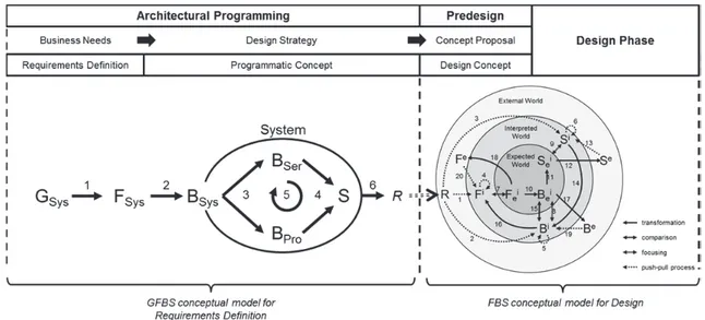
La phase de programmation architecturale, comme toute phase conceptuelle, est basée sur une grande quantité d’informations vagues et incomplètes qu’il est nécessaire d’analyser et de clarifier (Wang et al. 2002). Macmillan propose une structuration de cette phase en deux étapes (Macmillan et al. 2001) : la première consiste à traduire les besoins métiers de haut niveau en une stratégie de conception tandis que la seconde concerne le développement de cette stratégie de conception en propositions de concepts architecturaux (Figure 1). La programmation architecturale se concentre sur la première étape de cette représentation de la phase conceptuelle.
La programmation architecturale est reconnue comme étant l’une des phases les plus importantes dans le déroulement des projets de construction (Shen et al. 2004; Yu et al. 2005; Tzortzopoulos et al. 2006). Les études préliminaires, la programmation architecturale et les études de conception représentent près de 10% du coût total d’un projet de construction, le reste étant dédié à la construction du bâtiment (Certu 2010). Au cours de ces phases, près de 75% des coûts globaux du projet sont engagés (Faatz 2009; Certu 2010). Paulson, et plus tard MacLeamy, ont déjà démontrés que ces phases amont ont la plus grande influence sur le projet de construction tout en ayant les plus faibles coûts en termes de modifications (Paulson 1976). Il s’agit là de la meilleure opportunité d’amélioration pour un projet de construction (Figure 2).
1.2.
Spécificités des Projets de Construction
La programmation architecturale se distingue de la phase conceptuelle des autres domaines d’ingénierie de par la nature même de son objet d’étude. Un bâtiment est défini par de nombreuses exigences et contraintes à satisfaire à un niveau social, urbain, fonctionnel, technique autant que économique, d’insertion dans le paysage et de protection de l’environnement, relatives
4
à sa réalisation ainsi qu’à son utilisation (DGUHC & Certu 1999; JORF 2007). Tous ces éléments constituent un ensemble considérable d’informations hétérogènes, imprécises et incertaines, issues de sources multiples qu’il est nécessaire de rassembler et traiter tout au long du processus de programmation architectural (Shen et al. 2004).
La programmation architecturale se base sur une définition incertaine des besoins métiers de la MOA. Ces besoins métiers dépendent fortement du contexte local du projet de construction. La stratégie opérationnelle de la MOA qui en découle est étroitement liée aux exigences bâtiments qui sont à définir (Tzortzopoulos et al. 2006). La compréhension de cette stratégie est rarement complète, même pour la MOA qui éprouve des difficultés pour la décrire (Cooper & Press 1995; Barrett & Stanley 1999). Tout au long du projet, cette stratégie opérationnelle est également soumise à de nombreux changements et évolutions.
La programmation architecturale se confronte à de nombreux acteurs de nature complexe et manquant de coordination (Newcombe 2003; Tzortzopoulos et al. 2006) :
- La MOA et ses parties prenantes représentent trois types de clients : le ‘‘client payeur’’ (dit MOA), le ‘‘client utilisateur’’ (dit utilisateur), et le ‘‘client usager’’ (dit usager). Dans le cas des bâtiments publics, ces trois entités sont représentées par des personnes bien distinctes ayant un rapport différent avec le bâtiment. Dans l’exemple d’un lycée, le MOA est le Ministère de l’Education Nationale qui finance le projet. L’utilisateur est représenté par le personnel de l’établissement (p. ex. les enseignants, le directeur, le concierge…). Ce personnel est nécessaire à la transmission de connaissance aux élèves, usagers de l’établissement.
- La Maitrise d’œuvre (MOE) (c.-à-d. les concepteurs) est généralement représentée par une équipe de conception regroupant un ou plusieurs cabinets d’architectes, divers bureaux d’études et autres consultants allant de l’économiste de la construction aux experts légaux. Cette équipe de conception n’est souvent pas encore définie au moment de la programmation architecturale (p. ex. dans le cas des concours d’architecture).
- Les entrepreneurs sont aussi représentés par une équipe de construction temporaire qui évolue tout au long du projet de construction. Chaque membre de cette équipe se voit assigner un certain nombre de taches interdépendantes au niveau du temps et du séquencement ce qui amène à des temps de construction longs et irréguliers (Kubicki et al. 2006).
Enfin, les bâtiments se distinguent également des autres types de produits (logiciel ou manufacturier) de par sa durée de vie relativement longue comparée à son usage intensif ainsi qu’aux coûts résultants de son cycle de vie (de sa conception à sa démolition). En général, un bâtiment a plusieurs secondes vies à travers la rénovation et la réhabilitation. De telles caractéristiques sont à prendre en compte au plus tôt dans le processus de développement de projet, ce qui impacte la phase de programmation architecturale.
1.3.
Etat de l’Art
D’après la littérature, les projets de construction souffrent de nombreux problèmes en termes de coût, de qualité et de délai impactant directement la satisfaction de la MOA. Il s’avère qu’une part importante de ces problèmes est originaire de la phase de programmation architecturale (Allégret & Guilleux 2000; DGUHC 2000; Love & Li 2000; Yu et al. 2008; Feng & Tommelein 2008; Certu 2010; AQC 2013). Un panorama historique (Bousbaci 2004), pratique (Duerk 1993; Cherry 1999; Hershberger 1999; Barrett & Stanley 1999; Allégret et al. 2005a; Certu 2010) et littéraire (Kamara et al. 1999; Green & Simister 1999; Kamara et al. 2002; Shen et al. 2004; Yu et al. 2005; Kiviniemi 2005; Yahya et al. 2007; Bogers et al. 2008; Chung et al. 2009; Huovila & Hyvarinen 2012; Koutamanis 2013; Hassanain & Juaim 2013) de la programmation architectural met en évidence de nombreuses difficultés relatives à cette phase des projets de construction.
Les pratiques de programmation architecturale sont actuellement fortement dépendantes de l’expérience des architectes et des programmistes. Les bonnes pratiques, méthodes et approches
5
de programmation architecturale sont encore peu communiquées notamment car elles représentent un avantage concurrentiel aux professionnels offrant cette mission d’AMOA.
La MOA se repose entièrement sur la mémoire et les compétences du programmiste. Le processus de programmation architecturale est encore principalement réalisé de manière manuelle et sous format papier. Par conséquent, la cohérence globale et la complétude du programme restent souvent difficiles à assurer et manquent de clarté, sans oublier le temps perdu dans l’exercice. Quelques solutions sont apportées au niveau de la recherche sur les technologies de l’information et de la communication (p. ex. programmation architecturale assistée par ordinateur) avec plus ou moins de succès. Cependant, même si ces initiatives sont trop souvent focalisées sur le bâtiment plutôt que sur les besoins métiers et opérationnels de la MOA, elles nécessitent plus d’attention (Koutamanis 2013).
1.4.
Synthèse
La programmation architecturale, au même titre que la phase conceptuelle en ingénierie, est une étape essentielle dans un projet de construction. En effet, des décisions critiques doivent être prises par le MOA sur base d’une quantité importante d’informations vagues, instables et incomplète. Au travers de cet état de l’art, nous avons montré qu’il y a encore des améliorations à apporter en termes de pratiques, recherches et connaissances. Malgré une grande quantité de travaux sur le sujet, quelques pistes sont encore à explorer, notamment en ce qui concerne la relation entre les besoins stratégiques de la MOA (besoins métiers, opérationnels) et les exigences détaillées des clients utilisateurs et usagers (exigences bâtiment) (Kiviniemi 2005). Par conséquent, ces travaux de recherche se limitent à la formulation des exigences bâtiments sur base des besoins métiers de la MOA (Figure 3). Basée sur ces différents éléments, la Section 2 présente les objectifs industriels et scientifiques qui ont guidés ces travaux.
2. Objectifs
Cette section est divisée en deux parties : la première partie présente les objectifs industriels de ces travaux, tandis que la seconde en précise la problématique scientifique et les questions de recherche traitées dans ces travaux.
2.1.
Objectifs Industriels
Les objectifs industriels présentent le cadre de ces quatre années de recherche en se basant sur des problèmes pratiques. Ces objectifs reflètent notre compréhension de la programmation architecturale sur base d’un état de l’art du domaine et d’observations faites sur le terrain (c.-à-d. entretiens, pratiques et formation professionnelle).
Le cadre de ces travaux se limite aux bâtiments publics multi-utilisateurs dans les limites de la Loi sur la MOA Publique (Loi MOP) française (JORF 2010). Dans ce contexte, la programmation architecturale se doit d’être réalisée par la MOA (assistée d’un professionnel de la programmation : le programmiste) avant consultation de la MOE qui ne peut y être impliquée. Le programme est le seul document transmis à la MOE lui permettant de comprendre et de répondre aux besoins de la MOA. Au-delà d’un certain coût, un concours d’architecture est obligatoirement mis en place. Dans ce contexte, la MOA se retrouve devant plusieurs difficultés : définir un programme seul (ou presque), évaluer des propositions architecturales et les comparer sur base de ce programme. De plus, ses connaissances sur le projet sont souvent limitées à une compréhension partielle de ses propres besoins métiers et une appréciation encore plus restreinte des besoins et activités des utilisateurs et usagers. Ces entités sont généralement inconnues ou indisponibles au moment de la programmation architecturale.
Cette recherche se focalise sur sept problèmes pratiques relatifs au programme et aux méthodologies de programmation architecturale (Figure 4) :
a. les programmes ‘‘copier-coller’’ où un même programme est utilisé pour deux projets d’un même type sans réelle prise en compte du contexte local (SC-Construct Project),
6
b. les conflits entre exigences dans le programme (Barrett & Stanley 1999; Tzortzopoulos et al. 2006),
c. le manque de précision dans la définition de ces exigences (Barrett & Stanley 1999; Tzortzopoulos et al. 2006),
d. les exigences implicites (Barrett & Stanley 1999),
e. le manque de complétude des programmes (Barrett & Stanley 1999; Kamara et al. 2002; Shen et al. 2004; Yu et al. 2007),
f. l’absence de formalisme et de normes en programmation architecturale (formation PAMO du GEPA), ainsi que
g. le manque de réelle compréhension commune des besoins métiers de la MOA, des utilisateurs et des usagers (Kelly et al. 2002; Kamara et al. 2002; Yu et al. 2006; Kalay 2001).
Les problèmes pratiques relatifs aux comportements humains des parties prenantes tels que leur degré d’implication (Egan 1998), la communication entre parties prenantes (Yahya et al. 2007; Tzortzopoulos et al. 2006), ou les problématiques de collaboration (Kalay 2001) ne font pas partie du cadre de ces travaux.
La résolution de chacun de ces problèmes pratiques n’est pas réalisable en un seul projet. Ce projet de recherche se limite donc à la définition d’un cadre et d’un outillage méthodologique pour la partie fonctionnelle du programme dans le cas des constructions publiques. La partie fonctionnelle du programme se concentre sur la description des activités à réaliser dans le futur bâtiment (Gobin 2003) menant à la définition des espaces nécessaires et de leurs relations en termes de dépendance.
Ce but se décompose en plusieurs objectifs. Ces objectifs sont à considérer comme des principes à prendre en compte dans la définition du cadre et des outils méthodologiques. Ils représentent des indicateurs de performances de la solution proposée. L’objectif de ces travaux n’est pas de les satisfaire complètement mais plutôt d’analyser la façon dont chacun d’entre eux est abordé dans la proposition finale :
Objectif 1 – Aider la MOA, les utilisateurs et les usagers à exprimer leurs exigences en prenant en compte les aspects de complétude, de pertinence et de fiabilité de ces exigences (Barrett & Stanley 1999; Kelly et al. 2002; Kamara et al. 2002; Shen et al. 2004; Tzortzopoulos et al. 2006; Yahya et al. 2007; Yu et al. 2007; Feng et al. 2009).
Objectif 2 – Supporter l’analyse et le traitement de ces exigences en termes de consistance,
maturité, traçabilité et dépendances entre elles afin de permettre une aide à la décision tout au
long du processus de programmation (Barrett & Stanley 1999; Kamara et al. 2002; Gobin 2003; Tzortzopoulos et al. 2006; Yahya et al. 2007; Yu et al. 2007; Feng et al. 2009; Certu 2010).
Objectif 3 – Spécifier les exigences de manière claire et utile afin de permettre leur
validation par la MOA, leur utilisation par la MOE. Cette spécification doit refléter l’état des
pratiques de la MOE par rapport à ses outils actuels (p. ex. outils et langages informatiques d’aide à la conception).
Objectif 4 – Vérifier que les exigences demandées par la MOA sont bien implémentées par la MOE (adéquation programme-projet de manière objective).
Chacun de ces objectifs concerne une étape différente du processus de programmation architecturale. Les contributions issues de ces travaux de recherche constituent une première étape dans la poursuite de cette stratégie.
2.2.
Objectif Scientifique
A partir des éléments présentés dans les sections et sous-sections précédentes, il nous semble que la programmation architecturale fait référence à un processus de traduction des besoins
7
métiers de la MOA en exigences bâtiment. Ceci implique qu’il existe un lien entre les besoins stratégiques de haut niveau (c.-à-d. orientés métiers) et les exigences techniques de plus bas niveau (c.-à-d. orienté bâtiment). Dans ce mémoire, les ‘‘besoins’’ sont considérés comme une expression brut de ce que la MOA veut, souhaite, ou désire, tandis que les ‘‘exigences’’ sont considérées comme une définition structurée et formalisée de ces besoins à destination de la MOE.
Dans le domaine de l’Architecture-Ingénierie-Construction, ce processus de traduction des besoins en exigences est fortement lié à l’expérience du programmiste. Au regard de l’état de l’art sur la programmation architecturale, les approches actuelles se caractérisent par une formalisation plutôt tardive des besoins en exigences (Figure 5). Les besoins métiers sont généralement traduits en besoins bâtiment (c.-à-d. en termes d’espaces) avant d’être formalisés et structurés sous forme d’exigences bâtiment. Le processus de programmation a en effet tendance à être rapidement orienté vers la génération de principes de solutions architecturales.
Dans les autres domaines d’ingénierie, cette transition entre les besoins de haut niveau et les exigences de bas niveau est bien mieux tracée et formalisée. En Génie Mécanique, les besoins sont formalisés par des fonctions avant d’être déclinées en exigences produit. En Génie Logiciel, les besoins sont formalisés sous forme d’objectifs avant d’être opérationnalisés par des exigences sur les logiciels. En Génie Industriel, les besoins sont formalisés par des processus et des
activités avant d’être instanciés par des exigences sur les ressources. Ces fonctions, objectifs,
processus et activités sont des exigences de haut niveau, c’est-à-dire des formalisations de haut niveau des exigences sur leurs systèmes respectifs. Ces exigences de haut niveau sont de nature abstraite ce qui retarde le raisonnement sur les principes de solutions à mettre en place. La définition de ces exigences est pleinement supportée par un ensemble d’approches, méthodes, outils et techniques propres à chaque domaine.
L’objectif scientifique de ces travaux de recherche est de développer une méthode de programmation architecturale basée sur les connaissances issues de ces domaines d’ingénierie (c.-à-d. les Génies Mécanique, Logiciel et Industriel). Cette méthode devra expliquer la ou les
relations entre les besoins métiers de la MOA et les exigences bâtiment, ainsi que la transition
entre les besoins de haut niveau et les exigences de bas niveau. La méthode proposée vise à une formalisation amont (c.-à-d. tôt dans le processus) des besoins en exigences (Figure 6).
Pour atteindre un tel objectif, trois questions de recherche structurent la démarche :
QR1 : Quels sont les concepts nécessaires pour décrire un bâtiment et son domaine de définition ?
QR2 : Comment modéliser un bâtiment et son domaine de définition tout en intégrant les différents points de vue des parties prenantes impliquées ?
QR3 : Comment dériver les exigences bâtiment à partir des besoins métiers ?
La première question de recherche fait référence aux informations nécessaires pour décrire l’objet d’étude. La deuxième question de recherche porte sur le périmètre de l’objet d’étude et la cohérence des différents points de vue sur l’objet d’étude pouvant être pris. La dernière question de recherche demande plus de détails sur le développement des exigences bâtiments en partant des besoins métiers de la MOA.
2.3.
Synthèse
Dans cette section, nous avons présenté le cadre dans lequel cette recherche s’inscrit. Les motivations, intérêts et aspects prospectifs de cette recherche ont été établis au travers de divers constats au niveau des pratiques et des connaissances scientifiques sur la définition des besoins en Ingénierie. La volonté de conserver un aspect applicatif a pu être exprimée dans la description des objectifs industriels. Dans ce contexte, la problématique de recherche abordée dans ces travaux se focalise sur le transfert de connaissances sur la définition des besoins issues de divers domaines d’ingénierie vers le domaine de l’Architecture-Ingénierie-Construction.
8
3. Méthodologie
L’approche mise en place pour atteindre les objectifs présentés dans la Section 2 a été guidée par notre compréhension et perception de la programmation architecturale. Celle-ci est influencée par un certain nombre d’observations sur les similarités entre le domaine de l’Architecture-Ingénierie-Construction et les autres domaines d’ingénierie. Il en résulte l’identification de possible transfert de connaissances issues des Génies Mécanique, Industriel et Logiciel vers l’Architecture-Ingénierie-Construction afin de faire progresser la programmation architecturale. Cette approche s’appuie également sur une méthodologie de recherche issue de la Design Science et de la Design Research, ainsi qu’un certain nombre de cas d’études.
3.1.
Sciences de la Conception et Recherche en Conception
La méthodologie suivie au cours de cette recherche est un mélange de deux approches : l’approche de la Design Science proposée par (March & Smith 1995) et l’approche de Design Research proposée par (Blessing & Chakrabarti 2009). L’approche de March & Smith est structurée selon deux axes (Table 3) : le premier axe présente les activités de recherche : construire, évaluer, découvrir, et justifier, tandis que le second présente les résultats de recherche : concept, modèle, méthode et instanciation.
Nos travaux de recherche se limitent à l’activité de construction d’artefacts pour répondre aux objectifs industriels et scientifiques. Il s’agit là de poser les premiers éléments pour une recherche sur le long terme. Les autres activités de recherche sont réservées pour les perspectives. Cette activité de construction d’artefact est étendu sur l’ensemble des résultats de recherche définis par March & Smith afin d’assurer une continuité entre ces artefacts.
L’approche DRM (Design Research Methodology) introduite par (Blessing & Chakrabarti 2009) est utilisée comme élément structurant de la méthodologie de recherche appliquée dans ces travaux. Cette approche est composée de quatre étapes : la clarification de la recherche (RC), une première étude descriptive I), l’étude prescriptive (PS) et une seconde étude descriptive (DS-II). L’approche DRM est présentée comme un processus itératif avec diverses combinaisons possibles (sept types de recherche identifiés). La combinaison suivie dans cette thèse correspond au type 3 incluant : une RC basée sur une revue de la littérature, une DS-I également basée sur une revue de la littérature, une PS exhaustive et une initialisation de DS II (Figure 7).
3.2.
Cas d’Etudes
Ces travaux de recherche se sont appuyés sur trois cas d’études ex post facto et un cas d’étude en cours : un lycée luxembourgeois, une médiathèque française, une synagogue canadienne, et une bibliothèque universitaire luxembourgeoise. En Figure 8 sont représentés les documents utilisés dans chaque cas d’étude en tant que source d’information.
Le premier cas d’étude est celui qui a motivé ces travaux de recherche. Il s’agit de la rénovation et l’extension d’un lycée au Luxembourg (projet d’environ 10 M€). L’objectif de ce cas d’étude était d’évaluer l’impact d’une nouvelle organisation pédagogique à mettre en place dans le lycée sur les exigences bâtiment. Ce cas d’étude a permis d’établir un premier lien entre les objectifs de la MOA, les processus internes de l’établissement et les exigences spatiales.
Le deuxième cas d’étude est une médiathèque en France (projet d’environ 2 M€). L’objectif de ce cas d’étude était de retracer un certain nombre d’exigences fonctionnelles à partir du programme dans les synthèses réalisées par le programmiste (dans le diagramme fonctionnel) et par les différents cabinets d’architecture ayant répondus au concours (dans leurs projets architecturaux). Au travers de la modélisation du cycle du livre, ce cas d’étude a permis de développer une des contributions principales de ces travaux de recherche permettant de modéliser des liens informationnels entre le programme, le diagramme fonctionnel et les projets architecturaux notamment en s’appuyant sur les notions d’espaces et de relations fonctionnels.
Le troisième cas d’étude est une cuisine de synagogue au Canada (projet d’environ 50 k€). L’objectif de ce cas d’étude était d’évaluer deux propositions d’agencement de cuisine sur base d’un certain nombre de cas d’utilisation d’une cuisine et au regard des exigences spécifiques issue