Acknowledgements
Comme pour la plupart des projets, une thèse ne se réalise pas seul. Et, bien souvent, la réussite d’un travail tient aussi aux personnes qui y participent, qui nous soutiennent et qui nous entourent. C’est pourquoi j’aimerais re-mercier toutes les personnes qui ont participé, de près ou de loin, à la réussite de ce projet.
J’aimerais tout d’abord remercier mes encadrants Mónica Jiménez-Ruiz et Emmanuel Flahaut pour leurs conseils, leurs corrections et le temps qu’ils m’ont accordé quand j’en avais besoin. J’aimerais remercier particulière-ment Mónica qui a été très présente durant les moparticulière-ments les plus difficiles de cette thèse, et qui a su me donner le soutien nécessaire pour surmonter les obstacles rencontrés. Merci également aux membres du jury, Jean-Louis Bantignies, Marie Plazanet, Montserrat Gómez-Simon, Jean-Marc Escudier et Lucyna Firlej, pour avoir accepté d’évaluer mon travail, et de l’avoir fait avec bienveillance. Merci aussi à toutes les personnes qui m’ont aidé sur des parties plus spécifiques de mes travaux, Stéphane Rols, Jean-Marc Escudier, Corinne Payrastre, Jean-Louis Bantignies, Rozenn Leparc, Mohammed Zbiri, Juan Rubio-Zuazo et Miguel Angel Gonzalez, pour leurs contributions es-sentielles à la réalisation de ce travail. Merci ensuite aux hommes de l’ombre, Pierre Lonchambon, Alain Bertoni, Simon Baudoin et Raymond Aznar pour leurs compétences techniques et leur aide précieuse tout au long de ces trois années. Un grand merci bien sûr à mes collègues de travail, Jean-François Guillet, Cyril Sarrieu, Martin Boehm et Nikolaos Biniskos, pour leur soutien moral, et les discussions riches et parfois très drôles que nous avons eues. Et enfin, merci à toute ma famille et tous mes amis, pour leur soutien incondi-tionnel durant cette thèse, mais aussi depuis mes plus jeunes années.
Contents
1 Introduction 1
1.1 Nanomaterials : General introduction . . . 1
1.2 Functionalization of nanoparticles . . . 5
1.3 Toxicity of nanomaterials. . . 8
1.4 Carbon nanotubes. . . 14
1.4.1 Functionalization of carbon nanotubes . . . 16
Covalent functionalization . . . 16
Non-covalent functionalization . . . 19
Encapsulation . . . 20
1.4.2 Toxicity of carbon nanotubes . . . 21
In vitro and in vivo detection of the CNTs . . . 23
1.5 General motivation of the thesis. . . 25
2 Equipments and methods 29 2.1 Sample preparation . . . 29
2.1.1 Synthesis of the double-walled carbon nanotubes by CCVD . . . 29
Synthesis from a catalytic powder . . . 29
Extraction of the DWNTs from the composite powder . 30 2.1.2 Purification of the DWNTs . . . 30
Double oxidation . . . 31
Washing with NaOH . . . 32
Carboxyl groups activation . . . 33
Grafting of a diamine : 1,4-diaminobutane . . . 35
Grafting of the Fluorophore : Fluorescein Isothiocyanate . . . 37
Grafting of the Fluorophore : the streptocyanine . . . . 39
2.1.4 Reference samples . . . 40
Individual molecules . . . 41
Linker-fluorophores covalent bonding . . . 41
DWNT-fluorophores non-covalent grafting . . . 42
2.1.5 Sample Summary . . . 43
2.2 Inelastic Neutron Scattering spectroscopy . . . 43
2.2.1 Neutrons: properties and interest. . . 44
2.2.2 Basics of inelastic neutron scattering . . . 46
The scattering cross section . . . 46
Scattering from a single fixed nucleus . . . 48
Fermi’s golden rule . . . 49
Expression for the double differential cross-section . . 49
Coherent and incoherent scattering . . . 51
Incoherent inelastic scattering by crystals . . . 53
Correlation functions in neutron scattering . . . 55
2.2.3 Specificities of IN1-LAGRANGE spectrometer . . . 56
2.3 Density Functional Theory calculations . . . 59
2.3.1 The principle of DFT . . . 60
2.3.2 The Hohenberg-Kohn-Sham formulation of DFT . . . . 61
The Local Density Approximation (LDA) . . . 63
The Generalized Gradient Approximation (GGA) . . . 64
Other types of functionals . . . 64
2.3.3 The Lattice Dynamics . . . 65
2.4 X-ray Photoelectron Spectroscopy. . . 69
2.4.1 Principle . . . 69
2.4.2 Instrumentation . . . 70
X-ray Sources . . . 70
Electron Energy Analyzer . . . 72
2.4.3 Measurements . . . 72 Sampling depth . . . 72 Typical XPS spectrum . . . 73 Chemical Shift. . . 75 Quantification . . . 76 3 Experiments 79 3.1 Study of the grafting of the Fluorescein Isothiocyanate . . . . 80
3.1.1 X-ray Photoelectron Spectroscopy . . . 80
FITC . . . 81
DWNT-Diamine . . . 82
DWNT-diamine-FITC . . . 83
DWNT@FITC . . . 86
Process efficiency quantification from the DWNT-diamine-FITC sample . . . 87
3.1.2 Inelastic Neutron Scattering and DFT . . . 91
DFT calculations results . . . 94
INS evidences of the covalent grafting of the FITC . . . 97
Quantification of the grafting efficiency . . . 99
3.2 Study of the grafting of the Cyanine . . . 103
3.2.1 X-ray Photoelectron Spectroscopy . . . 103
Cyanine . . . 104
DWNT-diamine-Cyanine . . . 106
Process efficiency quantification from the
DWNT-diamine-Cyanine sample . . . 111
3.2.2 Inelastic Neutron Scattering . . . 115
DFT calculations results . . . 116
INS evidences of the covalent grafting of the Cyanine . 119 Quantification of the grafting efficiency . . . 122
3.3 Study of the adsorption energy for both fluorophores . . . 125
3.3.1 Adsorption energy study of the FITC . . . 126
3.3.2 Adsorption energy study of the Hemicarboxonium . . 131
4 Conclusions and Perspectives 137 A Other Spectroscopic Techniques 141 A.1 Raman spectroscopy . . . 141
A.2 Infra-Red spectroscopy . . . 145
B Multiphonon scattering 147 B.1 Multiphonon Scattering in Neutron Spectra . . . 147
B.1.1 Overtones . . . 149
B.1.2 Combinations . . . 149
B.1.3 Phonon Wings. . . 150
B.2 Application to the calculated DOS . . . 152
B.2.1 Method 1 : The Kearley’s approach . . . 153
Phonon Wings shapes . . . 153
Phonon Wings generation for different frequencies . . 154
B.2.2 Method 2 : The Dawidowski’s approach. . . 157
List of Figures
1.1 Pictures of the Lycurgus cup in reflected (a) and transmitted (b) light
[4]. And (c), high-resolution transmission electron microscopy
im-age of carbon nanotubes in a genuine Damascus sabre [5]. . . 2
1.2 (a) and (b) are in situ observations of crack nucleation and
propaga-tion in CNTs reinforced polystyrene (PS) composite thin films. The presence of the CNTs (A-D arrows) allowed an increase in tensile
strength for the PS of about 3 MPa [11]. (c) and (d) are confocal
microscopy images of aptamer-conjugated dye-doped silica nanopar-ticles in a mixture of three different cells allowing to sort the cells via
molecular recognition [14]. . . 3
1.3 (a) Photograph of a flexible and transparent MoS2field-effect
transis-tor device. (b) Reflection-mode optical micrograph of the same
flexi-ble and transparent device [26]. (c) Schematic of a ZnO
nanoparticle-based spray-coated transitor. (d) Scanning electron microscope
im-ages of the ZnO nanoparticle-based spray-coated layer [29].. . . 4
1.4 Transmission electron microscopy images of (a) nonfunctionalized,
(b) aminopropyltrimethoxilane functionalized silica nanoparticles, illustrating the effect of the covalent functionalization on the
dis-persion of the particles [34]. . . 6
1.5 Schematic of In Situ Synthesis of Polystyrene-Grafted Single-Wall
Nanotube Composites using carbanions interfacing the polymer ma-trix and the nanotubes, allowing to preserve the integrity of the
1.6 Evolution of the number of scientific publications in between 1989 and 2015 (using the keyword “nanomaterials” on the website PubMed.org
specialized in Biomedical and Life Science literature). . . 9
1.7 (a) TEM image showing the morphological aspects of the particles of
TiO2found in sunscreen commercial products (Bar = 100 nm) [52].
(b) Representation of TiO2 particle distribution in different layers
of minipig abdominal skin (longitudinal slice of skin), showing the results from the cross section analysis of each skin layer. Numbers in
parentheses are estimates of the numbers of TiO2 particles observed
in each layer, 24h post-exposure to the product. [53]. . . 12
1.8 (a) Light micrograph of lung tissue of a rat exposed to TiO2
nanopar-ticles at 3 months after exposure. This micrograph demonstrates
accumulation of TiO2 -containing macrophage aggregates (arrows)
[54]. (b) microspcopy image of a brain macrophage within 18 h
pos-texposure to TiO2. We see multiple vacuoles containing TiO2
aggre-gates. (c) higher magnification of (b) showing swelling and
disrup-tion of mitochondria in close proximity to the aggregates [58]. . . . 13
1.9 Representation of the main categories of carbon nanotubes. The
single-walled (SWNT), the double-walled (DWNT) and the
multi-walled (MWNT) carbon nanotubes. . . 15
1.10 Example of the grafting of poly(amidoamine) dendrons on MWNTs using the amidation functionalization process with previous carboxyl
groups activation [83]. 3-steps process with: 1) the oxidized, 2) the
activated, and 3) the functionnalized MWNTs. . . 17
1.11 Example of the functionalization of MWNTs with a
diaminotri-ethyleneglycol by means of 1,3-dipolar cycloaddition [94].. . . 18
1.12 Example of non-covalent functionalization of NTCs using pyrene
1.13 TEM images of CNTs internalized in murine myoblast stem cells[133]. (a) and (b) show inclusion bodies containing aggregated SWNTs. (c)
and (d) show a vesicle containing an aggregate of carbon nanotubes 22
1.14 Confocal microscopy images of cells incubated with SWNT/FITC: (A) bright field image; (B) fluorescence image; (C) Differential inter-ference contrast image under high magnification; (D) fluorescence image under high magnification; (E) overlay of C and D. Scale bars
are 100 µm for (A) and (B) and 10 µm for (C-E) [106]. . . 24
2.1 Illustration of the two steps of the double oxidation treatment. . . . 31
2.2 Amidation chemical equilibrium. . . 34
2.3 Carboxyl groups activation mechanism via the use of oxalyle chloride. 34
2.4 Grafting mechanism of the 1,4-diaminobutane via amide bond creation. 35
2.5 Proton trapping mechanism of the the DIEA. . . 36
2.6 Molecular structures of the Fluorescein and the Fluorescein
Isothio-cyanate (FITC). . . 37
2.7 Grafting mechanism of the FITC on the DWNT-diamine via thiourea
group formation. . . 37
2.8 Representation of the sample DWNT-diamine-FITC, after the
graft-ing process of the FITC onto the DWNT-diamine. . . 38
2.9 Molecular structures of the Hemicarboxonium the Cyanine and the
covalently grafted Cyanine. . . 40
2.10 Representation of the 11 samples selected for studying the grafting
of fluorophores onto double-walled carbon nanotubes. . . 43
2.11 Comparison of the relative size of the X-ray and thermal neutron
scattering cross section σ for various elements. . . 46
2.12 A representation of a simple scattering experiment. The incident neutrons strike a sample and some neutrons are scattered in the
2.13 Vertical cut of the IN1-LAGRANGE insert (secondary spectrometer) 57
2.14 Kinematical range of IN1-LAGRANGE over its wide scanning en-ergy range (26-500 meV). It represents the (Q, ω) region accessible
with the spectrometer. . . 59
2.15 Schematic illustration of Perdew’s view of the hierarchy of DFT
ap-proximations. Taken from [176]. . . 65
2.16 Classical potential energy curve for two atoms, showing a minimum
at separation at r0 that might correspond to the bond length. This
plot is a simplification of the situation within a crystal. Taken from [179]. . . 66
2.17 Illustration of the photoelectric effect on one core electron. . . 69
2.18 Main components of a typical XPS instrument . . . 71
2.19 Universal curve for the inelastic mean free path of electrons in a solid [193]. . . 73
2.20 Typical XPS spectrum of the fluorescein isothiocyanate in the
bind-ing energy range of 0-650 eV and measured with an Mg Kαradiation
at 1253.6 eV. . . 74
2.21 XPS spectrum in the C1s region of the Ethyl Trifluoroacetate[194]. . 75
3.1 Experimental results of XPS measurements in the N1s orbital of (a)
the FITC and (b) the DWNT-diamine, and respective results of the
fitting. . . 81
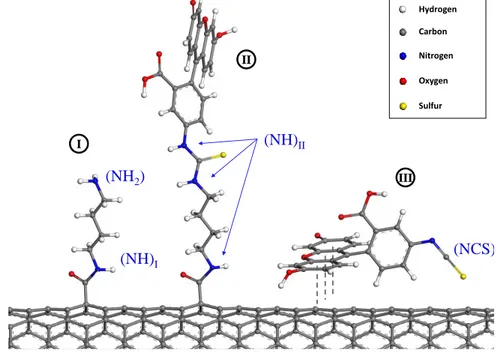
3.2 Illustration of the three models chosen for representing the surface
of the DWNT-diamine-FITC sample : (I) linker, (II)
SWNT-linker-FITC and (III) SWNT@Fluo. . . 84
3.3 Experimental results of XPS measurement of the
DWNT-diamine-FITC in the N1s orbital binding energy region, and results of the
3.4 Experimental results of XPS measurement of the DWNT@FITC in the N1s orbital binding energy region, and results of the fitting. The
spectrum is normalized to unity. . . 86
3.5 Representation of the results given by the Rccfor the
DWNT-diamine-FITC surface. . . 91
3.6 Representation of the results given by the Rncg and the Rcg for the
DWNT-diamine-FITC surface. . . 91
3.7 Representation of the three model systems and their respective
lat-tices, chosen for the DFT calculations. With (a) the SWNT-linker,
(b) the SWNT-linker-Fluo and (c) the SWNT@Fluo. . . 93
3.8 Comparison of the gH(ω)obtained via DFT calculations for the three
models : (a) the SWNT-linker, (b) the SWNT-linker-Fluo and (c) the
SWNT@Fluo. . . 96
3.9 Comparison of the experimental INS spectra obtained for the
refer-ence samples : Diamine (pink line), FITC (green line) and
Diamine-FITC (cyan line). . . 98
3.10 Comparison of the experimental INS spectra obtained for the
DWNT-diamine (blue line) and the DWNT-DWNT-diamine-FITC (red line) samples. 99
3.11 Comparison of the GDOSth (taking into account the multiphonon
contribution) with the INS experimental spectra for (a) the
DWNT-diamine and (b) the DWNT-DWNT-diamine-FITC samples. . . 102
3.12 Experimental results of XPS measurements in the N1s orbital of the
Cyanine and results of the fitting. The spectrum is normalized to unity.104
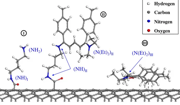
3.13 Illustration of the three models chosen for representing the surface of the DWNT-diamine-Cyanine sample : (I) linker, (II)
3.14 Experimental results of XPS measurement of the DWNT-diamine-FITC in the N1s orbital binding energy region, and results of the fitting using the reference samples. The spectrum is normalized to
unity. . . 108
3.15 Experimental results of XPS measurement of the DWNT@Cyanine in the N1s orbital binding energy region, and results of the fitting.
The spectrum is normalized to unity.. . . 110
3.16 Representation of the results given by the Rccfor the
DWNT-diamine-Cyanine surface. . . 115
3.17 Representation of the results given by the Rncg and the Rcg for the
DWNT-diamine-Cyanine surface. . . 115
3.18 Comparison of the gH(ω)obtained via DFT calculations for the three
models : (a) the SWNT-linker, (b) the SWNT-linker-Cya and (c) the
SWNT@Hemi. . . 118
3.19 Comparison of the experimental INS spectra obtained for the ref-erence samples : Diamine (pink line), Diamine-cyanine (light blue
line) and Cyanine (orange line) . . . 120
3.20 Comparison of the experimental INS spectra obtained for the DWNT-diamine (blue line) and the DWNT-DWNT-diamine-Cyanine (red line)
sam-ples. . . 121
3.21 Comparison of the GDOSth (taking into account the multiphonon
contribution) calculated for a mixing ratio of 60%/20%/20% with
the INS experimental spectra for the DWNT-diamine-Cyanine sample.123
3.22 Representation of the model SWNT@Fluo, chose for the calculation of single point energy of a FITC molecule interacting with a
single-walled carbon nanotube. . . 127
3.23 Energy profile of the interaction of the FITC and a single-walled
3.24 Representation of the model Graphene@Fluo chose for the calculation of single point energy of a FITC molecule interacting with a
mono-layer of graphene. . . 129
3.25 Energy profile of the interaction of the FITC and a graphene monolayer.130
3.26 Representation of the model SWNT@Hemi, chose for the calculation of single point energy of a Hemicarboxonium molecule interacting
with a single-walled carbon nanotube. . . 131
3.27 2D colormap energy profile of the SWNT@Hemi model, representing the variation of the energy of the system as a function of both the
SWNT - Hemicarboxonium distance and the torsion angle of the rings.133
3.28 Representation of the model Graphene@Hemi chose for the calcula-tion of single point energy of a Hemicarboxonium molecule
interact-ing with a mono-layer of graphene. . . 134
3.29 2D colormap energy profile of the Graphene@Hemi model, represent-ing the variation of the energy of the system as a function of both the Graphene - Hemicarboxonium distance and the torsion angle of the
rings. . . 135
A.1 Raman spectra of the FITC and the Cyanine samples with a 1064 nm excitation wavelength. Results obtained with 250 mW power
and 500 sec. accumulation time. . . 142
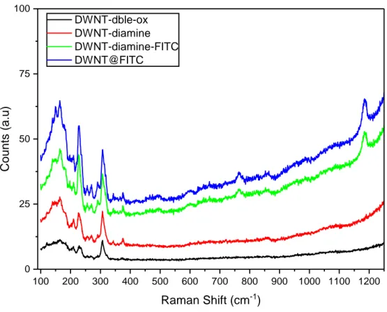
A.2 Raman spectra of the DWNT-dble-ox, DWNT-diamine, DWNT-diamine-FITC and the DWNT@DWNT-diamine-FITC samples with a 488 nm excitation
wave-length. Results obtained in 1 scan of 100 sec. accumulation time.. . 143
A.3 Raman spectra of the DWNT-dble-ox, DWNT-diamine, DWNT-diamine-Cyanine and the DWNT@DWNT-diamine-Cyanine samples with a 488 nm excitation
A.4 Infra-Red spectra of the Diamine-FITC, FITC, dble-ox, DWNT-diamine, DWNT-diamine-FITC and DWNT@FITC samples in the
low frequency range between 2000 and 800 cm−1. . . . 145
B.1 Experimental Spectrum of DWNT-diamine-FITC sample and
com-parison with its one-phonon DOS from DFT calculations . . . 148
B.2 Schematic representation of the consequences of the Overtones events
on INS spectra . . . 149
B.3 Schematic representation of the consequences of the Combinations
events on INS spectra . . . 150
B.4 Schematic representation of the consequences of the Phonon Wings
events on INS spectra . . . 151
B.5 Comparison of the external-modes and their consequences on the shapes of the generated Phonon Wings for (a) the DWNT-diamine
and (b) the DWNT-diamine-FITC samples . . . 154
B.6 Comparison of resulting Phonon Wings and their influence on the calculated DOS with the experimental spectra in the bending region
for (a) the DWNT-diamine and (b) the DWNT-diamine-FITC samples156
B.7 Comparison of resulting multiphonon contributions and their influ-ence on the calculated DOS with the experimental spectra for (a) the
List of Tables
2.1 Values of σcohand σinc for few elements. The units of σcohand
σincare barns (10−28m2) and the values are taken from Koester
(1977)[170]. . . 53
2.2 X-ray Satellites energies and intensities for Mg and Al sources
[192]. . . 72
3.1 Fitting parameters of the −NCS groups XPS peak from the
FITC sample.. . . 82
3.2 Fitting parameters of the −NH2 and −NH contribution to the
N1s peak from the DWNT-Diamine sample.. . . 83
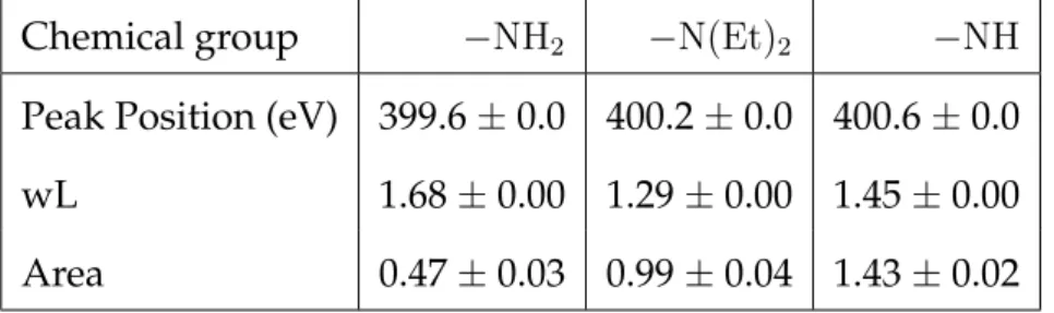
3.3 Characteristics of the different contributions to the N1s peak
from the DWNT-diamine-FITC sample. . . 85
3.4 Fitting parameters of the −NCS groups XPS peak from the
SWNT@FITC sample. . . 87
3.5 Relative proportions of the three models constituting the
DWNT-diamine-FITC sample given by the XPS measurements. . . 88
3.6 Vibrational modes of interest for the three model systems:
SWNT-linker, SWNT-linker-Fluo and SWNT@Fluo. . . 96
3.7 Fitting parameters of the −N(Et)2 groups XPS peak from the
Cyanine sample. . . 105
3.8 Characteristics of the different contributions to the N1s peak
3.9 Fitting parameters of the −NCS groups XPS peak from the
FITC sample.. . . 110
3.10 Relative proportions of the three models constituting the
DWNT-diamine-Cyanine sample given by the XPS measurements. . . 112
3.11 Vibrational modes of interest for the three model systems:
Chapter 1
Introduction
1.1
Nanomaterials : General introduction
Contrary to what one might think, the use of Nanomaterials is not new in mankind’s history. Indeed, according to literature the usage of nanomaterials dates back to traditional Chinese medicine [1] and, Mayan [2] and medieval painting [3]. Nanomaterials such as colorful inks made of colloid-sized gold nanoparticles were, for example, used in artistic applications such as the fa-mous Lycurgus cup [4] (Figure 1.1-a and -b). Even carbon nanotubes have been found in the steel of ancient Damascus blades that may explain the ex-ceptional mechanical properties of these materials at that time and has been the object of a Nature publication in 2006 [5] (Figure 1.1-c). Back then, of course craftsmen were not aware of the existence of a nanoscale, but by em-pirically optimizing their processes, they ended up making the firsts man-made nanomaterials.
Nevertheless, we had to wait until the 1950’s and Richard Feynman’s fa-mous talk entitled “There is Plenty of Room at the Bottom”, where he estab-lished the possibility to build materials atom by atom [6], to hear for the first time the first words on what later became known as Nanotechnology. Even-tually, it was with the discovery of the fullerenes [7], and the possibility to characterize and synthesize them, by Richard Smalley et al. in 1985 that the concept of nanomaterials became a reality. Ever since, there is a real effort
(c)
FIGURE1.1: Pictures of the Lycurgus cup in reflected (a) and
trans-mitted (b) light [4]. And (c), high-resolution transmission electron microscopy image of carbon nanotubes in a genuine Damascus sabre
[5].
from the scientist community to conquer this nano-scale world.
Indeed, in the size range below 100 nm the materials we know from bulk behave very differently and offer a large amount of possibilities in terms of resulting properties. First because multiple atoms or molecules behave dif-ferently from individual ones; larger size results in different behaviors in col-lisions with atoms. Secondly, because increasing the number of atoms in a system includes perturbations of the atomic energy levels leading to energy bands with fine structures [8]. Indeed, below 100 nm size the emergence of the effects of quantum confinement modifies the energy spectra of the mate-rials and leads to new electrical, thermal and optical properties. For example, Charles H. Olk and Joseph P. Heremans have shown experimental evidence that the outstanding electrical properties of carbon nanotubes (CNTs) were diameter dependent and were consistent with a density of states contain-ing Van Hove-type scontain-ingularities due to quantum-confinement [9]. Finally, another very important feature of nanomaterials is that they present a very high specific surface area. This implies that they have a very high fraction of their atoms at the surface and these atoms act very differently from the ones located in the bulk of a material [10]. Indeed, the atoms at the surface own
a higher energy and, therefore, the integrated energy of those atoms pro-vides a surface tension that changes the mechanical, electrical and thermal properties as well as the way these nanomaterials interact with their envi-ronment. Looking at the particular features mentioned above it is easy to understand why there has been such a growing interest for making new ma-terials at the nanoscale over the past decades. It is therefore not surprising that they have found, nowadays, applications in many fields such as Materi-als science, Biotechnology, Energy storage, Microelectronics, Nanomedicine, etc. For example, carbon nanotubes are commonly used for mechanical rein-forcement of composite materials (Figure1.2-a and -b) and progresses in that field allow good compatibility with a large variety of polymer matrices, as it has been summarized by J.N. Coleman et al. in 2006 [11], and even for other types of matrices such as metals [12] or ceramics [13].
(c)
(d)
FIGURE1.2: (a) and (b) are in situ observations of crack nucleation
and propagation in CNTs reinforced polystyrene (PS) composite thin films. The presence of the CNTs (A-D arrows) allowed an increase in tensile strength for the PS of about 3 MPa [11]. (c) and (d) are confocal microscopy images of aptamer-conjugated dye-doped silica nanoparticles in a mixture of three different cells allowing to sort the
Various Nanomaterials are also used as biosensors for molecular recogni-tion (Figure1.2-c and -d) or signal transductions [14,15] for bioanalysis, and are studied in order to develop more selective ways to deliver drugs by us-ing them as carriers targetus-ing specific cells within tissues [15–18]. Concern-ing research on energy storage, the surface properties of the nanomaterials described above make them good candidates for fast reversible storage pro-cesses and very different types of compounds (carbon-based, metal oxides, polymers, etc.) are studied [19–23]. Eventually, nanomaterials find as well applications in electronic devices or information storage [24] where their use allows for example to make flexible or transparent transistors [25,26], to en-hance the charges transport inside semiconducting materials or to develop new fast-making processes for the microelectronics industry such as inkjet printing or spray-coating [27–29] (see figure1.3).
c) d)
b) a)
FIGURE1.3: (a) Photograph of a flexible and transparent MoS2
field-effect transistor device. (b) Reflection-mode optical micrograph of the same flexible and transparent device [26]. (c) Schematic of a ZnO nanoparticle-based spray-coated transitor. (d) Scanning electron mi-croscope images of the ZnO nanoparticle-based spray-coated layer
Many of the properties described above are based on the high specific sur-face area of the nanomaterials, that make them systems with a total energy generally higher than their corresponding bulk materials. If this higher en-ergy is a major asset in terms of resulting properties, it is at the same time a major drawback in terms of stability. Indeed, all systems have a tendency to minimize their total energy and, an easy way to do it in the case of nanoma-terials is often to reduce their surface tension by agglomerating/aggregating over time, losing consequently the properties related to their high specific surface area. One of the common way to overcome this issue is through the functionalization of the surface of the nanomaterials in order to maintain their dispersion and homogeneity.
1.2
Functionalization of nanoparticles
The functionalization of nanoparticles is actually the cornerstone of the de-velopment of nanotechnologies. First of all because, as we mentioned previ-ously, the properties of such materials result directly from the individualiza-tion of these nanoscale objects, individualizaindividualiza-tion that requires to overcome their natural tendency to agglomerate. Then, because the vast majority of the applications deriving from these outstanding properties implies interac-tions with other types of materials (e.g. other nanoparticles, matrix, layers, molecules, etc.) in order to be integrated in larger size devices. And finally, because the functionalization is also one way of tuning and monitoring the intrinsic properties of nanoparticles. We distinguish nowadays two different approaches for these purposes: the non-covalent functionalisation and the covalent functionalization of the nanoparticles.
One of the many goals driving the study of the functionalization of nanopar-ticles is thus to prevent their agglomeration, improving their individualiza-tion and consequently maintaining their outstanding properties within a ma-terial or a device. Concerning the non-covalent functionalisation, lots of stud-ies have demonstrated that the use of surfactants for non-covalent functional-ization of nanoparticles provides very stable and homogeneous dispersions in common solvents, including water. Stable suspentions of CNTs have thus been obtained by compensating the effects of attracting weak interactions with ionic surfactants such as sodium dodecyl sulfate (SDS) [30], dodecyl-benzene sodium sulfonate (NaDDBS) [31], and other types of surfactants [32, 33]. Literature also shows that covalent functionalization can be used for dispersion stability improvement. For instance, the covalent functionaliza-tion of silica nanoparticles with amino-terminated alkoxysilan, poly(ethylene glycol)-terminated alkoxysilan or oleic acids have shown strong evidence of dispersion stability improvement [34,35] (see figure1.4).
FIGURE 1.4: Transmission electron microscopy images of (a)
non-functionalized, (b) aminopropyltrimethoxilane functionalized silica nanoparticles, illustrating the effect of the covalent functionalization
on the dispersion of the particles [34].
Another important aspect of the functionalization in the literature is to en-sure the good compatibility of the nanoparticles when integrated in devices or materials. The aim of this type of functionalization is often twofold. First
it plays the role of interface between the nanoparticles and any other type of materials of interest that would not be naturally compatible, but it also ensures that the nanoparticles keep their properties once integrated in more complex systems. For example, the effective use of carbon nanotubes in com-posite applications strongly depends on the ability to disperse the NTs ho-mogeneously throughout the matrix without destroying their integrity [36] (see figure 1.5). Good interfacial bonding is required to achieve load trans-fer across the CNT-matrix interface, a necessary condition for improving the mechanical properties of polymer composites [37–39].
FIGURE1.5: Schematic of In Situ Synthesis of Polystyrene-Grafted
Single-Wall Nanotube Composites using carbanions interfacing the polymer matrix and the nanotubes, allowing to preserve the integrity
of the SWNTs [36].
Finally, the studies on the functionalization of nanoparticles present also a strong interest concerning the modification of the nanoparticles proper-ties. Indeed several studies report the tunability or the enhancement of the original nanoparticles properties, or even the emergence of new prop-erties through their functionalization. For example, in 2005, Kolmakov et al. functionalized SnO2 nanowires with Pd nanoparticules for gaz sensing ap-plication. They discovered an enhancement of the exchanges on the SnO2 nanostructure surface, increasing the sensivity of the sensor, promoted by
the catalytically-active Pd nanoparticles [40]. In 2011, del Carmen Giménez-López et al. have evidenced that when encapsulated, single-molecule mag-nets inside nanotubes underwent a large degree of orientational ordering, and the magnetic guest molecules influenced the electrical resistance of the host nanotubes [41].
Due to their outstanding properties and the tremendous effort made in im-proving their functionalization in order to find new applications, the popu-larity of nanomaterials kept on increasing for the past decades and they are nowadays a major actor in materials science. This increase of both popularity and, consequently, new applications came with the beginning of their large scale production. As they are today more and more used in state-of-the-art materials and devices, and are already used in many consumer products [42], the questions of their toxicity and their potential impact on health and envi-ronment inevitably raised within the scientific community.
1.3
Toxicity of nanomaterials
The rapid expansion of nanotechnology promises to have great benefits for society, yet there is increasing concern that human and environmental ex-posure to manufactured nanomaterials may result in significant detrimental effects. We could wonder why such materials raised questions about their potential impact on health and environment. First of all, the very basic def-inition of a nano-object is to have at least one of its dimension in the range below 100 nm. Objects of this size can easily cross the physiological barriers of any living being and may be able to penetrate into cells, or even into their nuclei. It is even because of this specific property that they stand as excellent candidates for targeted drug delivery. Then, as it has been already discussed
previously, they exhibit new outstanding properties that are not yet fully un-derstood or discovered, and these properties can be changed when they in-teract with other types of materials or molecules. These latter facts make their behavior very difficult to predict when they interact with a complex en-vironment (e.g. inside human body, inside living cells, in aquatic media, etc.) and could lead to potential harmful effects on living beings by interfering with biological processes. Finally, and with respect to the previous points, we witnessed a huge increase in interest, studies, publications and new ap-plications related to the nanomaterials over the past decades. In particular since 2000 (see figure 1.6), and their large scale production, nanomaterials became easier and easier to produce, increasing the risk of finding these ma-terials in contact with the public and/or to be released, at some point along their life cycle into the environment.
20 63 8 19 28 9 19 11 1 17 15 6 15 51 6 12 69 7 10 11 0 80 70 62 55 50 47 35 62 14 98 53 4 33 5 19 8 15 2 94 53 47 53 40 56 34 18 21 8 1 1 9 8 9 1 9 9 0 1 9 9 1 1 9 9 2 1 9 9 3 1 9 9 4 1 9 9 5 1 9 9 6 1 9 9 7 1 9 9 8 1 9 9 9 2 0 0 0 2 0 0 1 2 0 0 2 2 0 0 3 2 0 0 4 2 0 0 5 2 0 0 6 2 0 0 7 2 0 0 8 2 0 0 9 2 0 1 0 2 0 1 1 2 0 1 2 2 0 1 3 2 0 1 4 2 0 1 5 N u m b e r o f p u b li c a ti o n Y e a r o f p u b l i c a t i o n
FIGURE 1.6: Evolution of the number of scientific publications in
between 1989 and 2015 (using the keyword “nanomaterials” on the website PubMed.org specialized in Biomedical and Life Science
liter-ature).
Nevertheless the question of the toxicity of nanomaterials is a very com-plex one, and is still today at the center of a vigorous debate. To begin with,
there is a lack of rules and regulations surrounding the use and the produc-tion of nanomaterials. The European Union (E.U.), encouraged by France, is leading the joint endeavor to establish a coherent regulation around this deli-cate topic. In 2006, the “Agence française de sécurité sanitaire de l’environment et du travail” (Afsset) produced a first public report [43] inventoring the dif-ferent types of known nanomaterials and their corresponding potential risks. This report paved the way toward a better evaluation of the nanomaterials hazards and encouraged the research effort on the topic. In 2010, the min-isters and representatives of member states in the European region of the World Health Organization (WHO) included nanomaterials in the «key en-vironment and health challenges of our time», in the Parma Declaration on Environment and Health [44]. In 2014, the french “Agence nationale de sécu-rité sanitaire de l’alimentation, de l’environnement et du travail” (Anses), based on the previous work of the Afsset, presented a report [45] updating the knowledge on the risks related to nanomaterials, and advising their in-clusion in the “registration, evaluation, authorisation and restriction of chem-icals” (REACh) E.U. regulation. Despite the many attempts to improve the safe handling of nanotechnology, there is still considerable doubt and uncer-tainty on this very hot topic, and there is still no definitive framework set up for their regulation.
First of all because the effectiveness of specific frameworks such as REACh is still discussed [46, 47], slowing down the implementation of such regula-tion frameworks. Then, because to fully understand the impact of a specific nanomaterial over its whole life cycle requires a large amount of studies (and therefore a tremendous amount of time and money), while on the other hand the number of new nanomaterials keeps on increasing, making very hard for the toxicity studies to catch up. Finally, because the toxicity studies some-times end up with contradictory conclusions, leaving the scientific commu-nity not able to find a consensus on the matter.
In order to illustrate all the complexity depicted in the previous remarks, lets focus, as an example, on the case of one of the most widely used nanopar-ticles: the Titanium dioxide (TiO2). The TiO2 nanoparticles find nowadays many applications in various domain, such as pearlescent or “metallic” paint formulations used in cosmetics, hard coatings, plastics, and self-cleaning ad-ditives for porcelain, ceramics, and specialty coating [48]. Other TiO2 appli-cations include filters that exhibit strong germicidal properties and remove odors, and TiO2has been used in conjunction with silver as an anti-microbial agent [48]. Furthermore, due to its photocatalytic activity, TiO2 has also been used in waste water treatment [49]. Finally, it is a common additive in many food [50] personal care, and other consumer products [51] (known as the additive E171). One very concerning use of the TiO2nanoparticles is in com-mercial transparent sunscreen protections, because of its capacity to absorb UV light although remaining transparent to visible light [48]. When used in such conditions, the TiO2 nanoparticles are in direct contact with the human skin but don’t seem to penetrate the body through an intact (undammaged) epidermis (see figure1.7) [52,53].
a)
b)
FIGURE1.7: (a) TEM image showing the morphological aspects of
the particles of TiO2 found in sunscreen commercial products (Bar = 100 nm) [52]. (b) Representation of TiO2 particle distribution in different layers of minipig abdominal skin (longitudinal slice of skin), showing the results from the cross section analysis of each skin layer. Numbers in parentheses are estimates of the numbers of TiO2particles
observed in each layer, 24h post-exposure to the product. [53].
Nevertheless, this type of products are often sprayed and released in the air, and are very likely to end up in the water after the users bathed in the seas or rivers. Yet, many data suggest that TiO2 nanoparticles could be absorbed through respiratory tract, digestive tract and damaged skin, into the body and distributed in organs such as lungs [54, 55], lymph nodes [56], liver [55, 57], kidneys [55] and the brain [58] (see figure1.8). As we know, nano-TiO2 has to travel along the body within blood before reaching at target organs. However, there is still today no regulation concerning the permitted use of this nanomaterial. Furthermore, when we look specifically at the literature concerning the toxicity of the TiO2 nanoparticles, we find both studies evi-dencing their toxicity [59, 60] and studies evidencing the absence of toxicity [61–63]. Eventually, even by comparing only the studies demonstrating the toxicity of the nano-TiO2we see that it is very hard to find a consensus about the parameter on which depends its impact on health or environment. In-deed, some studies define its toxicity to be size-dependent [58,64–66] while
some others conclude that the toxicity of this nanomaterial is rather depend-ing on its crystal structure [67–69].
a
b
c
FIGURE 1.8: (a) Light micrograph of lung tissue of a rat exposed
to TiO2 nanoparticles at 3 months after exposure. This micrograph demonstrates accumulation of TiO2 -containing macrophage aggre-gates (arrows) [54]. (b) microspcopy image of a brain macrophage within 18 h postexposure to TiO2. We see multiple vacuoles contain-ing TiO2aggregates. (c) higher magnification of (b) showing swelling and disruption of mitochondria in close proximity to the aggregates
[58].
Other types of nanoparticles that happened to be more and more used in state-of-the-art materials and devices for the past decades, are the carbon nanotubes [70]. Of course in the case of carbon nanotubes the situation is less complex because there are applications neither in the food industry (al-though it may be possible for food packaging) nor in cosmetics (to the best of our knowledge), so a direct contact with consumers seems, for the mo-ment, rather limited. However, for the same reasons why apparently con-tradictory results are published for TiO2 nanoparticles because their shape, surface chemistry, crystal phase, dispersion protocol and animal/cell models and exposure conditions usually vary from one study to another, the litera-ture dealing with the toxicity of CNTs is also difficult to properly analyse. We will now introduce basics about carbon nanotubes before discussing again later toxicity of CNTs in particular.
1.4
Carbon nanotubes
In the landscape of nanomaterials, the CNTs own a special position. Indeed, since their discovery in 1991 by Iijima [71], and their first synthesis in 1993 by Bethune et al. [72] and Iijima et al. [73], CNTs have evolved into one of the most intensively studied nanomaterials. They are held in part responsible for launching the nanotechnology revolution and have had motivated both fundamental scientists and engineers interested in applications due to the unique combination of their properties.
First, these molecular systems are nanometer-sized in diameter, but up to centimeters long, yielding an unprecedented length/diameter aspect ra-tio. Carbon nanotubes can be thought of as narrow strips of graphene rolled up into seamless tubes (figure1.9). They form spontaneously and efficiently under well-defined conditions either as single-wall nanotubes (SWNTs) or multiwall nanotubes (MWNTs). Under tension, nanotubes are two orders of magnitude stronger than steel at 1/6th of the weight. The melting point of nanotubes have been calculated from computer simulations to be about 4000 K in “ideal vacuum” [70]. Depending on the atomic structure of nanotubes, including diameter, single-wall nanotubes act as ballistic conductors of elec-trons or show semiconducting behavior [74, 75]. Carbon nanotubes seem to be also excellent conductors of heat [76].
FIGURE1.9: Representation of the main categories of carbon
nan-otubes. The single-walled (SWNT), the double-walled (DWNT) and the multi-walled (MWNT) carbon nanotubes.
The SWNTs usually have diameters comprised between 0.4 and 2.5 nm [77]. The MWNTs are constituted of several concentric tubes, and their number can vary from 2 to 50 concentric tubes. We usually distinguish the double-walled carbone nanotubes (DWNTs), owning only two walls, from the MWNTs (figure 1.9). The MWNTs present inner and outer diameters comprised respectivelly between 0.5 and 50 nm, and between 1.2 and more than 100 nm. The distance in between the walls of the MWNTs is equal to 3.4 Å [78,79], which corresponds to the distance between the layers of graphene constituing the graphite. SWNTs and DWNTs have a tendency to naturaly form bundles that can reach a size in diameter above 30 nm and a length of several micrometers, and in some cases up to the order of the centimeter. The MWNTs often tend rather to form disorganized tangles.
Nevertheless, as peculiar as they can be, compared to the rest of the nanoma-terials, carbon nanotubes are no exception to the rule: on the one hand, their functionalization have been widely studied leading to several application in several domains [10] and, on the other hand, the question of their toxicity is as well at the center of the current debate on the nanotoxicity [80].
1.4.1
Functionalization of carbon nanotubes
As for any other type of nanoparticles, we find two ways of functionaliza-tion for the CNTs: the covalent funcfunctionaliza-tionalizafunctionaliza-tion and the non-covalent one. The covalent functionalization allows to graft molecules to the outer walls and to the tips of the nanotubes via the creation of a strong bond (covalent bond). The formation of such bond modifies the structure of the CNT and therefore its properties. This is often the reason why the DWNTs are used instead of SWNTs, indeed they allow to use their outer walls for the covalent grafting of molecules while their inner wall remains unchanged and main-tain its properties. The non-covalent functionalization, on the other hand, is based on weak interactions ( π − π, Van der Waals, hydrophobic, ionic, etc.) that have no impact on the structure of the CNTs [81] while it can still impact the properties of the CNTs [82].
Covalent functionalization
We can distinguish different categories of covalent functionalization depend-ing on the chemical reactions involved in the graftdepend-ing process.
Esterification-amidation. This type of functionalization requires to use CNTs that own carboxyl (-COOH) groups at their surface, usually achieved prior to the grafting via their oxidation. The direct reactions between the car-boxyl groups and the alcool/amide groups that forms esters/amides groups are slow and reversible. Nevertheless, when the carboxyl groups are first turned into acyle chloride groups the reactions are fast and non reversible. This is why the functionalization by means of esterification/amidation al-ways requires a first “activation” step using either thionyle chloride or ox-alyle chloride, before addition of the alcool or the amine to graft (see figure
2.2). Tao et al. [83] functionalized this way MWNTs with a poly(amidoamine) and deposited afterwards silver nanoparticles that have been visualized by
TEM (see figure2.2). With the same process Gul et al. [84] grafted a diamine, the 2-(2-aminoethoxy)ethoxy)ethanamine, before to graft a fluorophore, the fluorescein isothiocyanate (FITC), on the diamine and therefore were able to track the CNTs in in vitro experiments. Singh et al. [85] functionalized SWNTs and MWNTs with other types of polyamines (putrescine, spermidine, sper-mine) in order to graft afterwards siRNA. Delgado et al. [86] succeeded to graft fullerenes owning amine groups onto oxidized SWNTs extremities. Fi-nally, biological molecules such as enzymes [87] or DNA [88], can also be grafted on CNTs by means of this process.
FIGURE 1.10: Example of the grafting of poly(amidoamine)
den-drons on MWNTs using the amidation functionalization process with previous carboxyl groups activation [83]. 3-steps process with: 1) the
oxidized, 2) the activated, and 3) the functionnalized MWNTs.
Halogenation. Another approach to graft molecules onto CNTs can be via halogenation. For instance, the fluoration of walls of CNTs increase their reactivity allowing the grafting of amines [89] or alkyles. Fluorated SWNTs have been thus obtained using different techniques [90, 91]. Same for the DWNTs where several techniques have been studied [92,93].
Cycloaddition. The cycloaddition allows to create pyrrolidine cycles on the CNTs walls by the reaction of a 1,3-dipolar compound (generally azomethine ylides) on a dipolarophile (6-carbon rings of the CNTs, for instance). Bianco et al. [94] functionalized MWNTs with a diaminotriethyleneglycol chain with this 1,3-dipolar cycloaddition process (Figure1.11). They also grafted anti-cancer and antifungal molecules such as the methotrexate [95] and the am-photericine B [96]. We find also other types of cycloaddition that have been perfomed on CNT [97–100].
FIGURE1.11: Example of the functionalization of MWNTs with a
diaminotriethyleneglycol by means of 1,3-dipolar cycloaddition [94].
Free-radical addition The free-radical addition is a method widely used because of its simplicity and efficiency. The common way to perform it is to use diazonium salts which are very unstable and turn easily into radical in-termediates that spontaneously react with the carbon atoms constituting the CNTs. Tour et al. [101] were the first to describe this type of functionalzation on CNTs using aryldiazonium salts. Later this same team improved the pro-cess by adding ionic liquids and potassium carbonate [102]. Ménard-Moyon et al. [103] developed a method of triple functionnalization using this pro-cess that allows to graft afterwards three different molecules with different functions on the same CNTs : Antibodies targeting, treatment of the targeted disease and marking of the CNTs for imagery purposes.
Non-covalent functionalization
This second way of functionalizing the CNTs is as well quite studied and commonly used. We find various types of non-covalent functionalization in the literature.
Surfactant and polymers. Examples of non-covalent functionalisation of CNTs using surfactant for dispersion purposes have been described earlier in the chapter 1.2. Similarly, several examples of functionalization of CNTs with polymers in order to make nanocomposites materials can be found as well in the chapter1.2.
Polycyclic aromatic compounds. The Polycyclic aromatic compounds own-ing an hydrophilic or hydrophobic function can help the dispertion of the CNTs. One of the most widely used molecules is thus the pyrene and its derivatives. Indeed, the pyrene is able to be adsorb on the walls of the CNTs (see figure1.12). For instance, Baek et al. [104] used pyrene derivatives, own-ing carboxyl and amine groups to fix DNA molecules on SWNTs, to make biodetectors (Figure 1.13). Salice et al. [105] fixed gold nanoparticles onto SWNTs via the use of pyrene molecules presenting a carbon chain contain-ing a thiol group (-SH). The fluorescent molecules are as well good candi-dates for non-covalent grafting onto CNTs. One of the most commonly used fluorophore, because of its very low cost, is the fluorescein isothiocyantate (FITC). We find then examples of oxidized SWNTs that were functionalized with FITC molecules simply adsorbed [106, 107]. The goal was not to im-prove the dispersion of the nanotubes, but to mark them in order to be able to easily track them in in vivo studies. Finally, we find also examples of aro-matic medicines that were adsorbed onto the CNTs [108–111].
FIGURE1.12: Example of non-covalent functionalization of NTCs using pyrene molecules adsorption to connect with porphirin
deriva-tives [112].
Biomolecules. In order to use the CNTs for biological applications, the in-teractions of the latter with different biomolecules such as proteins, nucleic acids, carbohydrates and lipids have been studied. For example, proteins were used for the CNTs dispersions in water [113–115]. We find also studies that used single-stranded DNA to perform the dispersion of the NTCs [116–
118].
Encapsulation
Another form of non-covalent functionalization of the CNTs is also per-formed by encapsulating molecules inside the nanotubes. Indeed once they are opened the CNTs can by filled by different types of compounds. A famous example of encapsulation is attributed to Khlobystov et al. [119] after succeeded at filling SWNTs with fullerenes C60. We also find in literature several examples of medicines encapsulated in the CNTs [120–122]. MWNTs filled with iron atoms demonstrated that they could be used as medecine vectors by gathering at a specific location using a magnet [123], and also that they could be used for experimental cancer treatment using the magnetic
hyperthermia thechnique [124]. Finally, the encapsulation is also commonly studied for tuning the properties of both encapsulated molecules and host carbon nanotubes. For example, L. Alvarez et al. have widely studied the reciprocal influence of different compounds, such as polyiodides [125, 126] or π-conjugated molecules [127–131], encapsulated inside CNTs.
1.4.2
Toxicity of carbon nanotubes
One of the major preoccupation related to the use of the CNTs concerns their potential toxicity toward living beings. As any other nanomaterial the poten-tial risks on the health and environment due to their large scale production are not yet fully determined, even if several research groups are trying to an-swer this very complex question.
First of all, the functionnalized CNTs can be internalized by living cells with-out showing any evidence of toxicity for them [132]. Two different routes of penetration have been found, and depend on the functionalization of the CNTs and their size : the endocytosis [132,133] (see figure1.13) and the pas-sive diffusion, i.e. the CNTs pass through the cell’s membrane by perforating it such as needles [134]. Jin et al. [135] have even shown that the CNTs en-tered via endocytosis could be expelled by means of exocytosis.
FIGURE 1.13: TEM images of CNTs internalized in murine
my-oblast stem cells[133]. (a) and (b) show inclusion bodies containing aggregated SWNTs. (c) and (d) show a vesicle containing an
aggre-gate of carbon nanotubes
However, the remaining catalytic compounds (metal nanoparticles) used for the synthesis of the CNTs are suspected to be toxic for the organisms, by forming free-radicals that could damage the proteins, lipids and the ge-netic materials contained by the cells. For example, the residual cobalt can damage the chromosomes [136] and Fe ions can be responsible for oxidative stress. Then, the CNTs have a tendency to agglomerate in aqueous media (and therefore in biological media), phenomenon that could render particu-larly hard for the organisms to eliminate them. Furthermore, the chemical modification of the walls of the CNTs (i.e. their functionalization) can influ-ence drastically their potential toxicity [136], being directly in contact with their near-environment. As well as the state of their walls influences directly the integration of the CNTs in biological media, and their interactions with the cells and the tissues. For example, the higher rate of functionnalization
of the CNTs, the better their dispersion, the easier seemed to be their elimi-nation through the kidneys [137]. On the contrary, CNTs with a low rate of functionalization appeared to accumulate in the organs (liver, spleen, lungs, etc.). We find also evidences that the CNTs diameter and length [138] can influence their toxicity. Indeed, the longer the tubes, the more intense are the inflammatory responses because their elimination from the body becomes difficult or impossible. Concerning the influence of their diameter, studies suggest that the SWNT exhibits a higher toxicity than the DWNTs [139] and the MWNTs [140]. Finally, both the purification and the functionalization of the CNTs seem to play a crucial role on the damages they can cause to organ-isms and the way they are eliminated.
The question of the characterization of CNTs within cells or organisms is central, especially to assess their presence in particular cell compartments. As illustrated above, images are often shown at relatively low magnification and can only reveal the presence of agglomerates. The challenge comes from the fact that the contrast of single CNTs (and in particular single- or double-walled CNTs) is extremely low (carbon in a carbon environment). The ques-tion of the in vivo detecques-tion of CNTs is developed in the next paragraph.
In vitro and in vivo detection of the CNTs
In order to visualize the internalization of the CNTs by the cells, the more used technique is by far the functionalization with fluorescent molecules. FITC is a good example as it is very cheap, and therefore widely used, for the covalent or non-covalent functionalization of CNTs by fluorophores. The fluorescence emitted by the molecule is therefore directly visible by means of confocal microscopy (Figure1.14) [106,132,141]. Nevertheless, using this technique requires to consider some important points : the covalent bonds between the CNTs and the fluorescent molecules must be able to resist to enzymatic cleavages. The non-covalent bonds have to be strong enough to
prevent the fluorescent molecule to be released during the experiment. Fi-nally, the functionalization is very likely to modify the CNTs behavior in the studied biological environment, as discussed earlier.
For all these reasons, which illustrate the drawbacks of the fluorescence tech-niques, other techniques have been developed for the in vitro and in vivo detection of the CNTs, such as the Infra-Red fluorescence microscopy [142– 144] (intrinsic fluorescence of the SWNTs only), the Raman spectroscopy [145, 146](for any type of CNTs but for given chiralities only [147]), or the two-photon excitation microscopy [148] but requires the use of very expensive ultra-fast lasers and can also cause thermal damage to certain cells or tissues [149].
FIGURE1.14: Confocal microscopy images of cells incubated with
SWNT/FITC: (A) bright field image; (B) fluorescence image; (C) Dif-ferential interference contrast image under high magnification; (D) fluorescence image under high magnification; (E) overlay of C and D. Scale bars are 100 µm for (A) and (B) and 10 µm for (C-E) [106].
operate and allows to track any type of CNTs, and as the alternative tech-niques present significant drawbacks (type of CNTs-dependent, expensive or damaging for the samples), it is very relevant to deeper investigate the assumptions inherent in the use of fluorophores for CNTs toxicity studies.
1.5
General motivation of the thesis
Like many other nanomaterials, carbon nanotubes (CNTs) have found ap-plications in many fields because of their outstanding chemical and physical properties, and are nowadays widely studied from materials science to na-noelectronics [77], and even in nanomedecine, where they have been used to elaborate drug delivery systems for cancer therapy, biosensors or contrast agents for magnetic resonance imaging [150–152]. The direct consequence of these modern applications is a growing interest in such nanomaterials and the increase in their large scale production [153], leading to an increasing risk of environmental and human exposure. It becomes therefore more and more relevant to evaluate their potential impact on the health and the en-vironment, and the toxicity studies on this topic are multiplying over the past decade [154–160]. For those toxicity studies it is often required to know the exact location of the CNTs accumulating, or simply circulating, inside organisms or cells. A very common way to track them in such conditions is to functionalize the CNTs with fluorescent molecules which would be il-luminated afterwards under a light with the appropriate excitation wave-length. Despite the fact that these fluorescence strategies are very cheap and easy to operate, they suffer from a major drawback: they assume that the fluorescent molecule would be permanently linked to the CNTs. It is how-ever reasonable to question this assumption as the fluorescent molecules are usually constituted by one or more 6-carbon rings which can interact with the delocalized electron cloud of the CNTs. These non-covalent bonds could
later lead to the desorption of the fluorophore once the CNTs reach the com-plex chemical environment of a living cell and even before entering the cell (formation of a corona of proteins or phospholipids competing with the ad-sorbed dye, pH decrease within lysosomes, etc.). Therefore, the fluorescence data could lead to wrong information about the CNT’s location. The con-sequence is that a number of published results may be questioned in terms of the actual distribution of the CNTs within cells or at the whole organism level (biodistribution), and the kinetics of this distribution. This may have very important consequences regarding the conclusions about their fate (ac-cumulation, excretion) and thus their toxicity in general. It is thus funda-mental to understand the grafting mechanisms and estimate the efficiency of the covalent functionalization of the CNTs as well as the amount of sim-ply adsorbed fluorophores. In order to answer to these questions, we pro-posed a new approach based on both qualitative and quantitative evaluation of the way the fluorophores are bonded to the DWNTs, by means of two different spectroscopic techniques. First, we performed X-ray photoelectron spectroscopy (XPS) which allowed to probe the surface of the samples and to understand the different types of interactions between the fluorophores and the DWNTs. Then we characterized the bulk of our samples with the help of inelastic neutron scattering (INS) techniques. Indeed, neutron techniques are especially sensitive to the Hydrogen atoms while they have a low sensi-tivity to the carbon ones. This property makes them a perfect probe of our samples, allowing to highlight the organic molecules since the information on the contribution of CNTs is much reduced. In addition to neutron tech-niques we used computational techtech-niques such as density functional theory (DFT) calculations (lattice dynamics) in order to gain a better understanding of our samples, provide hypothesis to strengthen data analysis and to be able to derive quantitative information from our experimental results.
This work presents our investigations on the functionalization of double-walled carbon nanotubes (DWNTs) with fluorophores.
First, we chose to study the functionalization of double-walled carbon nan-otubes (DWNTs) with a very common fluorophore, fluorescein isothiocyanate (FITC), widely used in toxicity studies for its very low cost and easy visual-ization by fluorescence microscopy. We also used a well-known three step functionalization process to graft the FITC on oxidized DWNTs [161,162].
In addition, we investigated the influence of the fluorophore’s geometry by studying a second fluorescent molecule, the cyanine 5Me(NEt2)2), which is not commercialized but presents a very different geometry compared to the FITC, allowing to compare how this parameter influences the functionaliza-tion when performed in the same condifunctionaliza-tions.
We also used models of these fluorophores and simulated their behavior in the surrounding of CNTs, providing more insights to the way they can be adsorbed on such nanoparticles.
Finally, it is important to add that the question of the nature of the grafting of a molecule onto CNTs is also interesting for the field of materials science in general and not only relevant for toxicity studies (stability of sensors includ-ing functionalized CNTs, functionalized CNTs dispersed within a nanocom-posites, etc.).
Chapter 2
Equipments and methods
2.1
Sample preparation
2.1.1
Synthesis of the double-walled carbon nanotubes by
CCVD
Synthesis from a catalytic powder
The double-walled carbon nanotubes (DWNTs) are synthetized by cat-alytic chemical vapor deposition (CCVD) from an oxide catcat-alytic powder (M g0.99Co0.0075M o0.0025O). After the synthesis a composite powder is ob-tained. Its composition is well known and, typically contains around 12 %m of CNTs (80 % DWNTs) and desorganized carbon. Concerning the DWNTs so-produced, their inner and outer diameters range from 0.5 to 2.5 nm and from 1.2 to 3.2 nm, respectively. The median inner diameter is 1.3 nm and the median outer diameter is 2.0 nm. The composite powder also contains 88 %m of unmodified magnesia, plus some carbon-coated metalic nanoparticules. It is thus necessary to further purify by applying several chemical treatments (extraction, purification, etc...) in order to obtain samples with high contents of DWNTs and low rates of impurities. These different steps are described hereafter.
Extraction of the DWNTs from the composite powder
The extraction treatment aims at dissolving the magnesia and the accessi-ble Cobalt an Molybdenum nanoparticules. To do so, 1 g of nanocomposite powder is placed in an erlenmeyer flask, and is wet with 3-4 g of deionized water, then completely immersed in 15 mL of Chloridric acid (HCl) 37%. The opening of the flask is closed with para-film and the mixture is sonicated for 10 min in an ultrasonic bath. The solution has a blue-green coloration at that point, related to the dissolution of the Co and Mo. After one night, the mix-ture is filtered using a cellulose nitrate membrane (0.45 µm pore size), and the first filtrate exhibits the blue-green characteristic coloration. The CNTs are then washed with deionized water until the filtrate becomes neutral. At this point, the extracted CNTs can be either kept wet for immediate chemi-cal treatments or can be dried using freeze-drying for later use. Concerning the freeze-drying, the CNTs are placed in a glass bottle which is filled with deionized water. They are then sonicated for 10 minutes in order to be well dispersed and are placed in a freezer, waiting for the freeze-drying proce-dure. The extraction efficiency is estimated around 12% of the nanocompos-ite starting material (in weight).
2.1.2
Purification of the DWNTs
The raw DWNTs sample obtained with the extraction treatment still contains remaining Co (3.5 %) and Mo (1.0 %), mainly in the form of nanoparticles tightly encapsulated inside carbon shells. When the DWNTs undergo oxida-tive treatments the carbon shells are as well chemically attacked allowing the acids to enter the shells and to dissolve the entrapped metallic nanopartic-ules.
Double oxidation
The double oxidation treatment is a two-step oxidative process (see Figure
2.1) that has been widely studied at the CIRIMAT [163]. We mainly use this process today for DWNTs purification because it presents many advantages. Indeed, not only it enables the elimination of the metallic impurities as it has been mentioned above, but also it leads to the degradation the amorphous carbon produced during the CCVD synthesis. It also allows the opening of the extremities of the CNTs. Finally, the double oxidation treatment has the property of creating functional oxygenated groups, mainly in the form of carboxyle (-COOH), at the tips but also on the sidewall of the CNTs due to the presence of surface defects. Strictly speaking, the creation of those groups at the surface is already considered as a first step of functionalization, and will be used as anchor points for the further steps of the grafting process.
FIGURE 2.1: Illustration of the two steps of the double oxidation
treatment.
Step 1: Oxydation with Nitric acid. To begin, 100 mg of raw DWNTs are put in a 250 mL round-bottom flask. Then, 100 mL of a Nitric acid (HNO3) solution with a concentration of 3M is added. The suspension is sonicated in an ultrasonic bath for 10 minutes in order to break the agglomerates and disperse the raw DWNTs. The suspension is then stirred and heated under reflux conditions at 130◦C for 24 hours, and then cooled down to the room temperature, the stirring is switched off in order to allow the decantation of the DWNTs. The suspension is filtered with a polypropylene membrane, the filtrate has a pale yellow coloration. Finally, the DWNTs on the membrane
are washed with deionized water until the filtrate becomes colorless and neu-tral. The yield of the oxidation step with Nitric acid is around 82 % so, 100mg of raw dry DWNTs usually lead to ca. 82g of oxidized material.
Step 2: Oxidation with a Nitric and Sulfuric acid mixture. Right after the first step of the double oxidation treatment, 100 mg of wet DWNTs are placed in a 250 mL round-bottom flask, and 100 mL of a mixture solution of Nitric acid and Sulfuric acid HNO3 65% / H2SO4 95% (1:3) are added. The suspen-sion is sonicated for 10 minutes in an ultrasonic bath for dispersuspen-sion purposes. It is then heated at 70◦C under reflux conditions for 5 hours. When the reac-tion is over, the suspension is cooled down to room temperature. The content of the round-bottom flask is diluted very slowly in deionized water (exother-mic che(exother-mical reaction and NOx vapor release), and then it is put aside for a night of decantation. Finally, the suspension is filtered on a polypropylene membrane (0.45 µm pore size). Please note that the filtrate shows a brown-orange coloration and the filtration is really slow. The so obtained oxidized DWNTs, are then washed with deionized water until the filtrate becomes col-orless and neutral. At this point the DWNTs can once again be kept wet for an immediate chemical treatment or freeze-dried. The efficiency of the oxi-dation with this Nitric acid and Sulfuric acid mixture is around 18 % (for a 5-hour treatment).
Washing with NaOH
After the oxidation treatments, an additional procedure is necessary in order to obtain high purity DWNTs. Indeed, during the oxidation treatments, car-boxylated carbon fragments (CCFs) are produced and coat the walls of the DWNTs. The CCFs must be removed before any further steps because they are highly chemically reactive. To do so, 100 mg of double-oxidized DWNTs are introduced in a round-bottom flask containing 200 mL of a NaOH (4M)
solution. The mixture is sonicated for one hour at room temperature in an ultrasonic bath and finally put aside at room temperature overnight. After the night, the suspension is filtered on a polypropylene membrane. The fil-trate typically has a brown-pink coloration. The DWNTs obtained are then washed with deionized water until the filtrate becomes colorless and neu-tral. As for the previous steps, the so obtained DWNTs can either be kept wet for further treatment or can be freeze-dried before storage. At this step the sample will be refered as “DWNT-dbl-ox”.
2.1.3
Steps toward the covalent grafting of the Fluorophore
Few changes have been made to the protocol established by Bortolamiol in a previous Ph.D. Thesis [161], in order to improve the efficiency of the grafting process. First of all, FITC, because of its high reactivity, can be degraded in water solution by reacting slowly with the solvent. However the last step of the functionalization process was originally performed using a water-based buffer solution of sodium hydrogen carbonate (0.1M ; pH=8.4). In order to avoid any risk of degradation of the FITC in this aqueous solution, the wa-ter has been replaced by anhydrous Tetrahydrofurane (THF) buffered with a “Hünig’s base” : N,N-diisopropylethylamine (DIEA). Finally, the freeze-drying of the DWNTs between the different functionalization steps leads to a significant agglomeration of the nanotubes, thus decreasing their disper-sion and consequently hindering the surface chemical reactivity with FITC. In order to avoid this issue, the different following steps of the process were performed directly, without any intermediate drying step of the sample.
Carboxyl groups activation
An amidation chemical reaction involve two functional groups : a carboxyl group and an amine group (see Fig. 2.2). The carboxyl group is provided