HAL Id: hal-01009015
https://hal.archives-ouvertes.fr/hal-01009015
Submitted on 14 Jan 2020HAL is a multi-disciplinary open access
archive for the deposit and dissemination of sci-entific research documents, whether they are pub-lished or not. The documents may come from teaching and research institutions in France or abroad, or from public or private research centers.
L’archive ouverte pluridisciplinaire HAL, est destinée au dépôt et à la diffusion de documents scientifiques de niveau recherche, publiés ou non, émanant des établissements d’enseignement et de recherche français ou étrangers, des laboratoires publics ou privés.
Distributed under a Creative Commons Attribution| 4.0 International License
The effects of Soil Structure Interaction on a reinforced
concrete bridge
Stéphane Grange, Luca Botrugno, Panagiotis Kotronis, Claudio Tamagnini
To cite this version:
Stéphane Grange, Luca Botrugno, Panagiotis Kotronis, Claudio Tamagnini. The effects of Soil Struc-ture Interaction on a reinforced concrete bridge. COMGEO I, 1st International Symposium on Com-putational Geomechanics, Apr 2009, Juan-les-Pins, France. pp.877-886. �hal-01009015�
THE EFFECT OF SOIL-STRUCTURE INTERACTION ON A
REINFORCED CONCRETE BRIDGE
St´ephane Grange
Laboratoire 3S-R (Sols, Solides, Structures-Risques) INPG/UJF/CNRS , Grenoble Universit´es, France Luca Botrugno
Dipartimento di Ingegneria Civile e Ambientale, Universit`a degli Studi di Perugia , Italy Panagiotis Kotronis
Laboratoire 3S-R (Sols, Solides, Structures-Risques) INPG/UJF/CNRS , Grenoble Universit´es, France Claudio Tamagnini
Dipartimento di Ingegneria Civile e Ambientale, Universit`a degli Studi di Perugia , Italy
ABSTRACT: This paper presents a numerical strategy to simulate the behaviour of a
three-piles viaduct made of prestressed concrete. The viaduct was tested pseudodynamically in ELSA laboratory (JRC Ispra, Italy). During the experimental program, only the three piles where tested, whereas the behaviour of the deck was simulated using the finite element method. The first part of the paper presents a numerical model of the viaduct based on Timoshenko multifiber beam elements and non linear constitutive laws. Comparisons with the experimental results show the good performance of the approach. In the second part, a parametric study is carried out showing the influence of Soil-Structure Interaction (SSI). Various types of soils are considered using a recently developed element representing a rigid shallow foundation. The macro-element is suitable for dynamic (seismic) loadings and it takes into account the plasticity of the
soil, the uplift of the foundation, P − θ effects and the radiative damping. Finally, the numerical
results are compared with the ones coming from a classical engineering approach using linear elastic springs at the base of the piles.
1 INTRODUCTION
In engineering, boundary conditions have to be correctly reproduced in order to simulate numer-ically the behaviour of a structure. Soil-Structure Interaction (SSI) can not be neglected. This is particularly true for slender structures like tall buildings or bridge piers. Their behaviour is different whether the structure is embedded in a solid rock or on a soft soil.
This paper presents a simplified numerical strategy considering SSI to model a three-piles viaduct tested in ELSA (JRC Ispra, Italy). It is divided into two parts:
• Part I: The viaduct is considered embedded in the soil. It is simulated using multifiber
Tim-oshenko beams and non linear constitutive laws based on damage mechanics and plasticity. Comparison with experimental results shows the performance of the approach.
• Part II: The influence of SSI is studied using a recently developed macro-element taking
radiative damping (Grange 2008), (Grange, Kotronis, & Mazars 2008a), (Grange, Kotronis, & Mazars 2008b). The macro-element approach consists in condensing all non-linearities into a finite domain and works with generalized variables (forces and displacements) at the centre of the foundation. This concept allows considerably decreasing the necessary degrees of freedom of the numerical model and the computational demand. The results of a classical engineering approach are finally provided, using linear elastic springs at the base of the piers. A comparison of the two approaches shows clearly the advantages of the new macro-element tool.
2 PART I: MODELING OF THE PSEUDO-DYNAMIC TEST
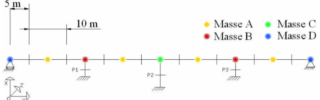
A partial 2.51 scaled viaduct was recently studied in ELSA (JRC Ispra) (figure 1).
Fig. 1. Viaduct: plan view of the tested bridge in Ispra at scale21.5.
The viaduct was tested pseudo-dynamically. This kind of hybrid experiment allows testing only a part of the structure, while the rest is simulated with a finite element code. Thus, only the three piles embedded into the soil were tested the desk being simulated with the element finite code Cast3M (figure 2). During the test, the interaction between the piles and the desk was calculated in real time thanks to a numerical integration of the dynamic equations. Inertial forces were calculated and imposed to the specimen by applying the adequate displacements.
Piles were made of reinforced concrete with a hollow rectangular section shape. The desk was composed of hollow voussoirs made of prestressed concrete. Details of the geometrical characteristics of the section are given in table 1.
Table 1. Viaduct: geometrical characteristics of the section of the desk.
A(m2 ) Ix(m4 ) Iy(m4 ) J(m4 ) Eb(P a) 1.11 0.13 2.26 2.39 25.109
2.1 Finite element mesh
A model using multifiber beams and concentrated masses is chosen to reproduce the structure (figure 3). The mass and rotational inertia details are given in table 2.
Fig. 3. Viaduct: model using multifiber beam elements and concentrated masses.
Table 2. Viaduct: masses and rotational inertias. n MassM (kg) Rotational inertia Ix(kg.m
2 ) Rotational inertiaIz(kg.m 2 ) A 27.5 285 234 B 32 287 271 C 34 288 322 D 13.75 143 117
Non-linear Timoshenko multifiber beam elements are used to reproduce the behaviour of the piles (Kotronis 2000), (Kotronis & Mazars 2005) and (Mazars, Kotronis, Ragueneau, & Casaux 2006). Six elements are used for the piles P1 and P3 and nine elements for the pile P2. Mesh is refined at the base of the piles where damage tends to be important. The desk being from prestressed concrete, its behaviour is assumed linear and it is discretised using linear beam elements. 40 concrete fibers and 80 steel fibers (representing the reinforcement bars at their actual position) are used in each section. Details of the fibers are provided in (Botrugno 2008).
2.2 Material parameters
The uniaxial version of the damage constitutive law (LaBorderie 1991) is used to reproduce the behaviour of concrete and the (Menegotto & Pinto 1973) law for steel. The parameters of
the damage constitutive law are fitted according to experimental concrete sample tests results. Details of the material parameters are provided in table 3.
Table 3. Viaduct: material data used for concrete and steel constitutive laws. Concrete parameters Steel parameters
E 29.4GP a E 200GP a ν 0.175 fy 450M P a Y01 1000P a fsu 710M P a Y02 0.0001M P a ǫsh 0.0060 A1 7000M P a− 1 ǫsu 0.10 A2 6.0M P a− 1 B1 1.0 B2 1.3 β1 0.5M P a β2 −19M P a σf 3.0M P a
Note: The test being pseudo-dynamic, the Rayleigh damping coefficient used in the numeri-cal model has to be small. Its value has been chosen equal to 0.5%.
2.3 Experimental versus numerical results: modal analysis
Natural frequencies for the embedded structure are given in table 4. Modal deformed shapes are given in figure 4. x y Mode 1 Mode 2 Mode 3 Mode 4
Fig. 4. Viaduct: deformed modal shapes for the modes 1 to 4 of the bridge. mode frequency (Hz) Test Simulation 1 4.2 4.2 2 6.6 6.8 3 9.8 10.4 4 16.1 16.8
Table 4. Viaduct: comparisons between the experimental and the numerical modal frequencies.
The numerical model is able to provide accurately the first four natural frequencies of the bridge. It is thus obvious that it reproduces correctly the masses, the stiffness and the boundary conditions of the experiment.
2.4 Accelerations imposed to the structure
The accelerations imposed to the structure are coming from a synthetic accelerogram with a 5% spectral response fitted according to Eurocode 8 for a soil of class B (EC8 2005). The figure 5(a) shows the comparison between the synthetic spectral response and the design spectra of the Eurocode 8.
The synthetic accelerogram is presented in figure 5(b). The peak of accelerations is situated at 0.35g (“low” earthquake). A second similar accelerogram (dilated, non represented here), is also imposed at the base of the structure. Its peak of acceleration is equal to 0.7g (“strong” earthquake).
0 1 2 3 4 5 6 7 8 9 10 -4 -3 -2 -1 0 1 2 3 4 Time (s) acc élération (m/s ) 2 Séisme faible 0 0.5 1 1.5 2 2.5 3 3.5 4 -10 -8 -6 -4 -2 0 2 4 6 8 10 Time (s) acc élération (m/s ) 2 Séisme faible Echelle 1 Echelle 1/2.5 (a) (b) (c)
Fig. 5. Viaduct: (a) Design spectra coming from the Eurocode 8 for a 5% damping and synthetical accelerogram spectra, (b) low level earthquake signal for the scale1 structure and (c) for the scale 1
2.5structure.
Note: The specimen being at 2.51 scale, accelerograms have to be modified in order to respect the similitude laws. Accelerations are thus multiplied by 2.5 and time is divided by 2.5. The low earthquake (0.35g at scale 1) is provided in figure 5(c) at scale 1
2.5.
2.5 Experimental versus numerical results: dynamic analysis
Experimental and numerical results of the dynamic analysis for the embedded structure are pre-sented in figures 6 and 7. The two earthquakes are considered. Theses figures show the evolution of the shear forces at the base and the lateral displacements at the top of the piles P1, P2 and P3 according to time. 0 0.5 1 1.5 2 2.5 3 3.5 4 -0.04 -0.02 0 0.02 0.04 0.06 Time [s] Disp [m]
Horizontal displacement at the top, Piers P1-P3
0 0.5 1 1.5 2 2.5 3 3.5 4 -0.08 -0.06 -0.04 -0.02 0 0.02 0.04 0.06 0.08 Time [s] Disp [m]
Horizontal displacement at the top, Pier P2
0 0.5 1 1.5 2 2.5 3 3.5 4 -800 -600 -400 -200 0 200 400 600 800 Time [s] Shear Force [kN]
Shear Force at the base, Piers P1-P3
0 0.5 1 1.5 2 2.5 3 3.5 4 -400 -300 -200 -100 0 100 200 300 400 Time [s] Shear Force [kN]
Shear force at the base, Pier P2 Expérience Numérique Expérience Numérique Expérience Numérique Expérience Numérique
Fig. 6. Viaduct: comparison between the experimental and numerical displacements and shear forces for the low earthquake.
The non linear behaviour of the bridge is correctly reproduced. Not only the the peaks are well simulated in the two directions but also the frequency contents of the response.
0 0.5 1 1.5 2 2.5 3 3.5 4 -0.1 -0.05 0 0.05 0.1 Time [s] Disp [m]
Horizontal displacement at the top, Piers P1-P3
0 0.5 1 1.5 2 2.5 3 3.5 4 -0.2 -0.15 -0.1 -0.05 0 0.05 0.1 0.15 Time [s] Disp [m]
Horizontal displacement at the top, Pier P2
0 0.5 1 1.5 2 2.5 3 3.5 4 -800 -600 -400 -200 0 200 400 600 800 Time [s] Shear Force [kN]
Shear Force at the base, Piers P1-P3
0 0.5 1 1.5 2 2.5 3 3.5 4 -400 -300 -200 -100 0 100 200 300 400 Time [s] Shear Force [kN]
Shear force at the base, Pier P2 Expérience Numérique Expérience Numérique Expérience Numérique Expérience Numérique
Fig. 7. Viaduct: comparison between the experimental and numerical displacements and shear forces for the strong earthquake.
3 PART II: INFLUENCE OF SOIL-STRUCTURE INTERACTION (SSI)
In this second part of the article, two modelling strategies are proposed to take into account SSI. The first uses a recently developed macro-element considering material and geometrical non linearities. The second is based on linear elastic springs at the base of each pile. Parametric studies taking into account two types of soils and comparisons between the different modelling strategies are detailed hereafter.
3.1 Types of soils
The first soil belongs to class B, according to the Eurocode 8 classification (EC8 2005). A rect-angular shallow foundation is considered at each pile with the following dimensions: Lx= 4.2m
and Ly = 2.1m. The second one is a class C soil. In order to amplify the influence of SSI, the
foundations are also taken smaller (Lx = 3.2m et Ly = 1.6m). The characteristics of both soils
are given in the table 5.
3.2 Calibration of the linear springs
For the second model and in order to reproduce the behaviour of the soils, the stiffness of the linear springs have to be calibrated. The following energy criterion is chosen: the stiffness of the springs is such that they accumulate the same energy as the non-linear SSI macro-element (figure 8).
Note: The dissipated energy produced by the macro-element within the hysteresis loops is not taken into account.
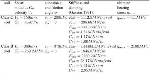
Table 5. Viaduct - SSI: Characteristics of the soils used for the parametric study.
soil Shear cohesion c Stiffness and ultimate
modulusG0 and friction damping bearing
velocityVs angleφ (Gazetas 1991) stressqmax
Class CVs= 150m/s cu= 200kP a Kθθ= 1112.5M N m/rad qmax= 1.1M P a
soil G0= 45M P a φu= 0 Kzz= 298.68M N/m
Khh= 244.36M N/m
Cθθ= 4.34M N ms/rad
Czz= 1.17M N s/m
Chh= 1.00M N s/m
Class BVs= 360m/s cu= 370kP a Kθθ= 144484.1M N m/rad qmax= 2100M P a
soil G0= 259.2M P a φu= 0 Kzz= 1845.5M N/m Khh= 2260.2M N/m Cθθ= 23.17M N ms/rad Czz= 3.61M N s/m Chh= 2.95M N s/m M θ Macro-element Linear spring
Fig. 8. Viaduct - SSI: calibrating the stiffness of the elastic linear springs.
3.3 Numerical results considering SSI.
The results presented hereafter show the influence of SSI on the viaduct and this for two different types of soils (see table 5). Each time the numerical results are also compared with the behaviour of the bridge considered fixed (embedded in the soil).
SSI - class B soil Only the results for the strong earthquake are presented in this section (figure 9). Three different boundary conditions are considered: embedded (Fixed), with the non-linear macro-element (ME), and with the linear springs (EL). Results are similar in terms of inter-nal forces. Nevertheless, the maximum displacements at the top of the piles are significantly increased (multiplied by 2) for the cases considering SSI (ME and EL).
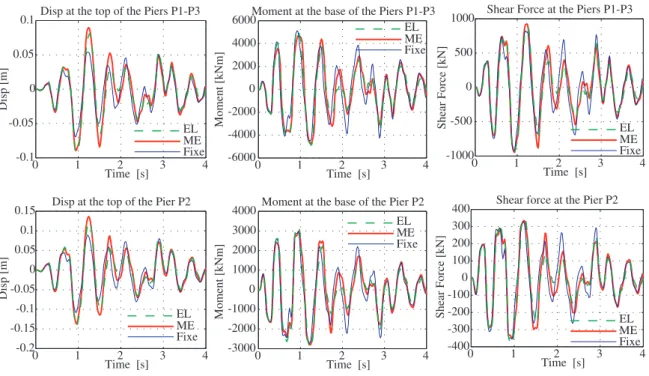
SSI - class C soil Due to numerical problems, only the results for the low motion are presented in figure 10 for the class C soil. This time, the behaviour of the viaduct is different depending on the boundary conditions. The displacements are strongly amplified (multiplied by 4) in the case of the structure lying on the macro-element and on the linear elastic springs. In terms of internal forces at the base of the piles (moments and shear forces), they are reduced significantly only for the case of the macro-element. They are almost equal for the embedded structure and for the one on the elastic linear springs.
0 1 2 3 4 -0.1 -0.05 0 0.05 0.1 Time [s] Disp [m]
Disp at the top of the Piers P1-P3
0 1 2 3 4 -0.2 -0.15 -0.1 -0.05 0 0.05 0.1 0.15 Time [s] Disp [m]
Disp at the top of the Pier P2
0 1 2 3 4 -6000 -4000 -2000 0 2000 4000 6000 Time [s] Moment [kNm]
Moment at the base of the Piers P1-P3
0 1 2 3 4 -3000 -2000 -1000 0 1000 2000 3000 4000 Time [s] Moment [kNm]
Moment at the base of the Pier P2
0 1 2 3 4 -1000 -500 0 500 1000 Time [s] Shear Force [kN]
Shear Force at the Piers P1-P3
0 1 2 3 4 -400 -300 -200 -100 0 100 200 300 400 Time [s] Shear Force [kN]
Shear force at the Pier P2
Fixe ME EL Fixe ME EL Fixe ME EL Fixe ME EL Fixe ME EL Fixe ME EL
Fig. 9. Viaduct - SSI: comparisons of the displacements, moments, shear forces for the strong motion and the class B soil.
0 1 2 3 4 -0.08 -0.06 -0.04 -0.02 0 0.02 0.04 0.06 0.08 Time [s] Disp [m]
Disp at the top of the Piers P1-P3
0 1 2 3 4 -0.1 -0.05 0 0.05 0.1 0.15 Time [s] Disp [m]
Disp at the top of the Pier P2
0 1 2 3 4 -5000 0 5000 Time [s] Moment [kNm]
Moment at the base of the Piers P1-P3
0 1 2 3 4 -3000 -2000 -1000 0 1000 2000 3000 Time [s] Moment [kNm]
Moment at the base of the Pier P2
0 1 2 3 4 -800 -600 -400 -200 0 200 400 600 800 Time [s] Shear Force [kN]
Shear Force at the Piers P1-P3
0 1 2 3 4 -400 -300 -200 -100 0 100 200 300 400 Time [s] Shear Force [kN]
Shear force at the Pier P2 Fixe ME EL Fixe ME EL Fixe ME EL Fixe ME EL Fixe ME EL Fixe ME EL
Fig. 10. Viaduct - SSI: comparison of the displacements, moments and shear forces for the low motion and for the class C soil.
4 CONCLUSION
In this article we propose a new simplified numerical strategy to reproduce dynamic Soil-Structure Interaction (SSI). Based on the macro-element approach, it is validated using a three-pile rein-forced concrete viaduct tested pseudo-dynamically in ELSA laboratory.
Two simulations are presented: The first one considering the structure embedded in the soil and the second one taking into account SSI and this for two types of soils (class B and C). After validating the numerical model with the experimental results of the viaduct considered embedded in the soil, the influence of SSI is quantified introducing the macro-element at the bottom of each pile. It is found that SSI isolates the structure as global forces and damage are found significantly reduced. Finally, comparison with an engineering approach based on linear elastic springs calibrated using an energy criterion shows clearly the advantages of the new macro-element. More specifically when considering SSI:
• for a class C soil (low mechanical characteristics), internal forces at the base of the piles are
found reduced compared to the ones provided considering the piles fixed. The displacements at the top of the structure are strongly amplified (multiplied by 4).
• for a class B soil (higher mechanical characteristics), non-linearities are concentrated
prin-cipally at the base of each pile. In other words, the resisting moment of concrete guides the behaviour of the structure. The resisting force of the pile is reached before the resisting mo-ment of the system{soil+foundation}. The procedure is similar as if the piles were embedded
in the soil, except for the displacements that are amplified (multiplied by 2).
Finally, the limits of the classical engineering approach based on elastic linear springs are evident. The results are found conservative. Internal forces and displacements are higher from the ones coming from the macro-element which reproduces better the non-linear behaviour of the viaduct. Moreover, the calibration of the stiffness of the elastic springs in the engineering approach is a quite difficult task.
Based on the results obtained within this work, it appears now possible to use the macro-element tool in design offices and research groups to investigate numerically the behaviour of a wider variety of configurations that is practically impossible to study experimentally.
5 BIBLIOGRAPHY REFERENCES
Botrugno, L. (2008). Analisi della riposta sismica di un ponte in cemento armato. Dipartimento di Ingegneria Civile e Ambientale, Universit`a degli Studi di Perugia, Italy.
EC8 (2005). NF P 06 030-1, NF EN 1998-1, Eurocode 8 : Calcul des structures pour leur r´esistance aux s´eismes. AFNOR. Partie 1 : R`egles g´en´erales, actions sismiques et r`egles pour les bˆatiments, Septembre.
Gazetas, G. (1991). Foundation Engineering Handbook, Chapter 15. Fang H-Y (ed.), van Nos-trand Reinhold: New York.
Grange, S. (2008). Mod´elisation simplifi´ee 3D de l’interaction sol-structure: application au g´enie parasismique. http://tel.archives-ouvertes.fr/tel-00306842/fr/. Ph. D. thesis, INP Grenoble, France.
Grange, S., Kotronis, P., & Mazars, J. (2008a). A macro-element for a circular foundation to simulate 3d soil-structure interaction. International Journal for Numerical and Analytical Methods in Geomechanics. 32(10), 1205–1227.
Grange, S., Kotronis, P., & Mazars, J. (2008b). A macro-element for a shallow foundation to simulate soilstructure interacfoundation considering uplift. Acad. Sc. Comptes rendus -Mecanique 336, 856–862. http://dx.doi.org/10.1016/j.crme.2008.10.002.
Kotronis, P. (2000). Cisaillement dynamique de murs en b´eton arm´e. Mod`eles simplifi´es 2D et 3D. http://tel.archives-ouvertes.fr/tel-00074469/fr/. Ph. D. thesis, ENS de Cachan, France.
Kotronis, P. & Mazars, J. (2005). Simplified modelling strategies to simulate the dynamic be-haviour of r/c walls. Journal of Earthquake Engineering 9(2), 285–306.
LaBorderie, C. (1991). Ph´enom`enes unilat´eraux dans un mat´eriau endommageable: mod´elisation et application l’analyse des structures en b´eton. Ph. D. thesis, Universit´e Paris VI, Paris, France.
Mazars, J., Kotronis, P., Ragueneau, F., & Casaux, G. (2006). Using multifiber beams to account for shear and torsion. applications to concrete structural elements. Computer Methods in Applied Mechanics and Engineering 195(52), 7264–7281.
Menegotto, M. & Pinto, P. (1973). Method of analysis of cyclically loaded reinforced concrete plane frames including changes in geometry and non-elastic behaviour of elements un-der combined normal force and bending. IABSE Symposium on resistance and ultimate deformability of structures acted on by well-defined repeated loads, final report, Lisbon, 328p.
ACKNOWLEDGEMENTS
The authors would like to thank the colleagues of the ELSA laboratory for providing the experi-mental results of the viaduct.