HAL Id: hal-01620032
https://hal.archives-ouvertes.fr/hal-01620032
Submitted on 6 Nov 2019
HAL is a multi-disciplinary open access
archive for the deposit and dissemination of
sci-entific research documents, whether they are
pub-lished or not. The documents may come from
teaching and research institutions in France or
abroad, or from public or private research centers.
L’archive ouverte pluridisciplinaire HAL, est
destinée au dépôt et à la diffusion de documents
scientifiques de niveau recherche, publiés ou non,
émanant des établissements d’enseignement et de
recherche français ou étrangers, des laboratoires
publics ou privés.
Behaviour and damage of injected
carbon-fibre-reinforced polyether ether ketone: From
process to modelling
Florentin Berthet, Frederic Lachaud, Jérémy Crevel, Marie-Laetitia Pastor
To cite this version:
Florentin Berthet, Frederic Lachaud, Jérémy Crevel, Marie-Laetitia Pastor. Behaviour and damage
of injected carbon-fibre-reinforced polyether ether ketone: From process to modelling. Journal of
Composite Materials, SAGE Publications, 2017, 51 (2), p. 141-151. �10.1177/0021998316642000�.
�hal-01620032�
Behaviour and damage of injected
carbon-fibre-reinforced polyether ether
ketone: From process to modelling
F Berthet
1, F Lachaud
2, J Crevel
1,2and M-L Pastor
3Abstract
Short-carbon-fibre-reinforced polyether ether ketones are materials of great interest for the aeronautical industry. In this study, a design of experiment was carried out to understand the effect of process parameters on micro- and macro-scale properties of injection-moulded short-carbon-fibre-reinforced polyether ether ketone (90HMF40). Mould tem-perature was found to be the most significant parameter; it had a positive effect, essentially on failure stress and strain. Once the damage and plasticity scenarios were understood, a micromechanical model based on Mori–Tanaka homogen-ization theory was developed, featuring micro-damage and coupling with macro-plasticity. This model gave good pre-dictions for quasi-static tensile tests.
Keywords
Polyether ether ketone, carbon fibre, injection moulding, modelling
Introduction
Composite materials are of major interest in the trans-port field, especially in aircraft construction, because of their excellent specific properties.1,2They are made up
of reinforcement particles lighter than commonly used materials, such as steel, which are incorporated in a resin to transfer stress. Thermosetting resins, such as epoxy, are used for their easy processing3 and good mechanical properties, but they are difficult to recycle.4 It is because they avoid this inconvenience that thermo-plastic resins are of great interest. In addition, they have better impact and chemical (aeronautical fluids) resistance.2,5 The aviation-certified-thermoplastic cur-rently used is PEEK (polyether ether ketone), which has been largely investigated since its first commercial-ization by ICI in the 1980s. The addition of short carbon fibres considerably improves the mechanical properties of the composite.6The best known carbon-fibre-reinforced PEEK used in the aeronautical field is the unidirectional AS4-APC2 prepreg, manufactured in
an autoclave.7 With this process, only simple and
double curvature parts can be produced, and the injec-tion-moulding technique is widely used for complex shapes. Moreover, short fibres can reinforce parts, depending on the distribution of their orientation,
length and concentration.8,9 Hence, the major limita-tion of this process is related to the lower strength of materials obtained by injection compared to autoclaved laminated composites.10Another problem encountered
concerns the prediction of how the material will behave in a structure as the microstructure (fibre and matrix properties) can be altered by process parameters, lead-ing to a heterogeneous material. Thus, it is essential to take these modifications into account when predicting material behaviour, a step that is not performed in a macroscopic model. The aim of the multi-scale model-ling approach is to predict heterogeneous material behaviour from its microstructure and component properties.11,12 The mean-field theory is one of the
1Ecole des mines Albi-Carmaux, ICA (Institut Cle´ment Ader), Universite´
de Toulouse, France
2ISAE-SUPAERO, ICA (Institut Cle´ment Ader), Universite´ de Toulouse,
France
3IUT-Universite´ Paul Sabatier, ICA (Institut Cle´ment Ader), Universite´ de
Toulouse, France Corresponding author:
F Berthet, Ecole des mines Albi-Carmaux, Alle´e des sciences, ICA (Institut Cle´ment Ader), Universite´ de Toulouse, Campus Jarlard, Albi 81013 CT Cedex 09, France.
possible ways to attain this objective. This analytical path is easier to implement than full-field homogeniza-tion (based on finite elements) and is less time
consum-ing. Shear lag models have been developed13,14 for
injected material but are restricted to one dimension. Models based on Eshelby’s solution with a non-dilute composite material enable a three-dimensional stiffness tensor to be predicted. Bounding models (Voigt, Reuss, Hashin-Shtrikman, Lielens)15–19can monitor the valid-ity of any models developed but are little used for
mechanical prediction. The self-consistent model
designed by Hill20is implicit and results in the material being too stiff. However, the well-known Mori–Tanaka model, improved by Benveniste,21 is very efficient for fibre-reinforced-composites.
Thus, the aim of the present study was first to under-stand the effect of process parameters on micro- and macro-scale properties. In the case of injection-mould-ing, the main parameters of the microstructure: fibre length22,23and orientation distributions,24–26
crystallin-ity,27and fibre28and void29content, are altered by
cer-tain process parameters30–32 and have an effect on
mechanical properties.33–35 Taguchi’s table enabled the effect of injection-moulding parameters on trad-itional mechanical properties to be understood. Differential scanning calorimetry, density measure-ments, chemical dissolutions and section observations by scanning electron microscope (SEM) gave access to the microstructure state. Secondly, a Mori–Tanaka homogenization scheme was implemented using previ-ously characterized microstructure parameters and variations. The non-linear behaviour of the matrix required a linearization of the problem in order to come within the domain of validity of the mean-field theory.36,37 In addition to problems of matrix non-linearity, the bonding between fibres and resin is rarely perfect,38,39 so a damage criterion was imple-mented, based on the work of Fitoussi et al.40
Experimental set-up
Material
PEEK, a semi-crystalline thermoplastic polymer, has
very good mechanical and chemical properties,5 see
Table 1.
Moreover, it has a glass transition temperature of
143!C and a melting temperature of 343!C, which
enable it to be used at high temperature.2
In this study, a commercial grade carbon-fibre-rein-forced PEEK was used: 90HMF40 provided by
Victrex!. The material contained 40 wt% of short
carbon fibres (high-modulus carbon fibres with a
mean length of 120mm) and an easy flow PEEK
grade. Test specimens, manufactured according to
ASTM D3641 - 10 a,41 were moulded with a DK 65/
160 injection-moulding press.
Design of experiments
In order to understand the influence of processing param-eters on mechanical and damage properties, an L9 Taguchi table was used42(Table 2). It enabled four par-ameters to be varied on three levels. Each parameter was chosen according to physical limits and previous works.43–46 Finally, the mould temperature (Tmould) was
chosen to be above the PEEK glass transition tempera-ture and below the PEEK degradation temperatempera-ture of 420!C.47 The holding pressure (P
hold) was chosen so as
to avoid shrink (low-holding pressure) and flash (high-holding pressure), and the (high-holding time (thold) (time for
which the holding pressure was applied) and cooling time (tcool) (time from the end of holding time to part ejection)
were also chosen in order to avoid cold slug. All param-eter levels are given in Table 2. For Tmould, the levels
were those measured during manufacturing. The tem-perature of the hopper was 50!C, the barrel profile temperature was 385!C–390!C–395!C, and the nozzle temperature was 405!C for all experiments. To obtain stable experimental results, the first five parts made in each trial were not taken into consideration.
Characterization
Monotonic and cyclic tensile tests were carried out on a testing machine with hydraulic grips respecting stand-ard NF ISO 527-2,48 with a crosshead speed of 5 mm/ min (approximately 2 e" 3s" 1) at room temperature (23!C). Young’s modulus, strength and fracture strain were determined as the mean of at least three tensile tests. For cyclic tensile tests, special care was taken during the unloading of the stress, to avoid a compres-sive state.
In order to understand the damage phenomena after tensile tests, the fracture surfaces were observed by SEM with a Nova NanoSEM 450. Samples were platinum–palladium coated in a QUORUM Q150RS sputter coater to avoid electrical charges.
Temperature was measured during the tensile tests to understand the non-linear behaviour of the material. The infrared camera was a Flir SC7000 set to an acqui-sition frequency of 50 Hz. Its operational range was from þ 20!C to 50!C with a NETD lower than 25 mK
Table 1. Mechanical properties of PEEK (Victrex!PEEK 90 G). Tensile Young’s modulus (MPa) Failure tensile stress (MPa) Failure tensile strain (%) 3700$ 100 110$ 1 15$ 1
at 25!C. It featured an InSb detector with a wavelength of 3.5–5$ 0.25 mm and a focal length of 50 $ 0.5 mm.
Modelling
Mean-field homogenization
The homogenization scheme chosen to predict the mechanical behaviour of the carbon-fibre-reinforced PEEK was the model first developed by Mori and
Tanaka49 and improved by Benveniste.21 Like all
mean-field homogenization schemes, it is based on
Eshelby’s inclusion problem50 of the accommodation
of an inclusion in a matrix. The theory considers an inclusion (for example, a fibre) embedded in the matrix. It is an analytical and explicit model in which the stiffness tensor (LMT) is given by equation (1). The
equation can be solved by summing the effects of all phases. LMT ¼ Lm Iþ Ah i I þ Er ð r" IÞAr ! "" 1 # $ h i" 1 ð1Þ where Ar¼ " L½ð r" LmÞErþ Lm)" 1ðLr" LmÞ is the strain concentration tensor of the dilute Eshelby model, Xh i ¼r PNr¼1vrXr is the volume average oper-ator over the N phases, vr is the volume fraction of phase r, Lr (respectively, Lm) is the stiffness tensor of phase r (respectively, the matrix), Er is the Eshelby tensor of phase r, depending on its aspect ratio (length/diameter) and matrix stiffness tensor.
For this model, with the Eshelby tensor, inclusions (fibres here) are considered as isotropic. This is true for glass fibres but not for carbon fibres.21 A new model using an ‘autocoherent’ methodology51 will be devel-oped in order to take the orthotropic stiffnesses of carbon fibres into account. Although the anisotropy of carbon fibre was not considered here, we introduced
the fibre orientation distribution as plotted in Figure 7. Then, as can be seen in Table 5, this distribution induced different values for longitudinal and transverse moduli.
Non-linear behaviour: Elastoplastic phase
In this study, plasticity is considered macroscopically. Based on the basic law of plasticity, equation (2) with Von Mises equivalent stress, equation (3), plasticity was implemented by an implicit formulation.
f¼ !eq" R pð Þ ð2Þ !eq¼ ffiffiffiffiffiffiffiffiffiffiffiffiffiffiffiffiffiffiffiffiffiffiffiffiffiffiffiffiffiffiffiffiffiffiffiffiffiffiffiffiffiffiffiffiffiffiffiffiffiffiffiffiffiffiffiffiffiffiffiffiffiffiffiffiffiffiffiffiffiffiffi 3 2* ! " 1 3* tr !ð Þ & ' : !" 1 3* tr !ð Þ & ' s ð3Þ The hardening law R pð Þ was determined by an ana-lysis of cyclic tensile tests.
R pð Þ ¼ R0þ Rcrit: 1 " expð":pÞ½ ) ð4Þ A consideration of matrix plasticity, at micro scale, would require linearization of its mechanical behav-iour, for example, with the secant method.7,8
Non-linear behaviour: Damage criteria
Considering elastic fibres and an elastoplastic matrix, it was easy to model fibre/matrix interface damage. This micromechanical damage depends on fibre orientation according to load orientation. For this type of compos-ite, damage occurs at the fibre-matrix interface.40,51
Fitoussi determined a quadratic three-dimensional fibre-matrix interface failure criterion for discontinu-ous-reinforcement composite40(equation (5)). It requires the identification of three parameters: !R
n, the interface failure normal stress; #R
s, the interface failure shear stress and ’, the friction parameter. These parameters have been identified for unidirectional carbon fibre with PEEK matrix laminates by Lachaud.52Thus, the criter-ion has to be calculated around the diameter of the inter-face, using the local axis for each orientation to take the anisotropy of the damage into account. A damage vari-able can be calculated as the ratio of the number of times; the criterion is satisfied for each angular position around the fibre to the total number of points calculated.
!i n !R n # $2 þ #si #R s # $2 ¼ 1 if !i n4 0 #i s #R sþ !h iin "tanð’Þ ð Þ & '2 ¼ 1 if !i n+ 0 8 > > < > > : ð5Þ
Table 2. L9 design of experiments.
Trial no. Mould temp. (!C) Holding pressure (MPa) Holding time (s) Cooling time (s) 1 178 60 6 35 2 178 70 9 55 3 178 80 12 80 4 188 60 9 80 5 188 70 12 35 6 188 80 6 55 7 203 60 12 55 8 203 70 6 80 9 203 80 9 35 Test 203 80 12 35
Finally, a damage parameter was introduced in the stiffness matrix of the fibre in order to compute the global stiffness of the composite again.
Results and discussion
Mechanical and physical properties
The behaviour under quasi-static tensile loading is shown in Figure 1. The mean values of Young’s modu-lus (E), fracture strength (!R) and strain (eR) are
reported in Table 3.
In Figure 2, three zones can be seen: Zone 1 (s <100 Mpa), an elastic zone; Zone 2 (100 MPa < s < 260–270 MPa), where irreversible phenomena appear and Zone 3, a crack propagation region with a clear-cut increase in the average temperature.
The strength and failure strain of the 90HMF40 were high, so bonding between the fibre and the matrix might be good.
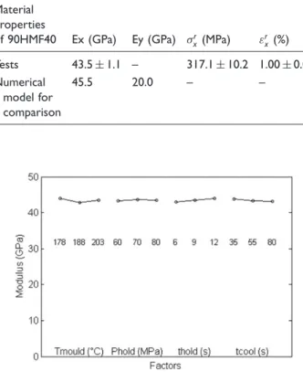
Design of experiments, analysis
Tensile results are given in Tables 3 and 4. The effects of injection parameters were determined (related to their levels) by multi-linear regression. It was possible to access the effects of parameters on the various results obtained from tensile tests (Figures 3 to 5). The ANOVA (analysis of variances) results are shown in Tables 5 to 7. The results show that the mould tempera-ture was the only significant factor affecting ultimate stress and strain.
Table 8 shows the effect of each injection parameter on the tensile properties for this PEEK.
At the levels of injection parameters use, holding pressure did not have a significant effect on tensile properties. The effects of holding time and cooling time were also not significant. Thus, mould temperature
was the most significant parameter, with a positive effect, essentially on failure stress and strain.
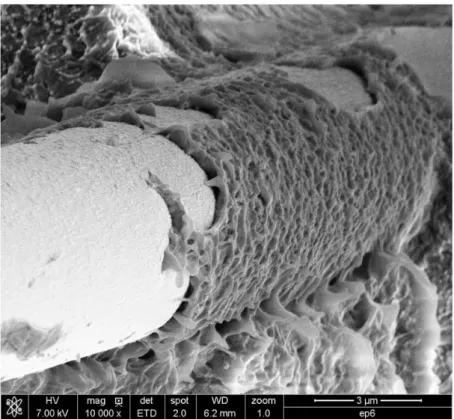
Damage characterization
In order to understand the damage behaviour, SEM microscopy was carried out (Figure 6). Two different mechanisms were noticeable: debonding (a) and matrix plasticity (b). This picture was taken on the fracture surface of a 90HMF40 specimen. It was observed that debonding was the most important phenomenon in the middle of the test specimen section, whereas matrix plasticity was the most prominent near the outer sur-faces. Thus, PEEK transcrystallinity (growth of crystal-linity perpendicularly to the fibre surface) had a significant effect on damage behaviour, as observed by Friedrich et al.53and Kim and Gao.54This crystal-linity is highly influenced by cooling rates (thermal
Table 3. Tensile results.
Trial no. Ultimate stress (Mpa) Ultimate strain (%) Young’s modulus (Mpa) 1 299.2 0.89 43,076 1 308.3 0.92 43,645 1 304.6 0.89 44,432 2 295.7 0.89 45,426 2 317.4 1.00 42,456 2 310.3 0.91 44,249 3 297.0 0.91 44,708 3 318.8 0.97 44,069 3 321.5 0.97 44,180 4 306.0 1.01 41,694 4 330.7 1.10 43,267 4 330.1 1.11 42,107 5 319.4 0.99 45,559 5 326.4 1.05 42,318 5 320.3 0.99 43,986 6 324.0 1.07 42,792 6 332.5 1.17 40,135 6 323.9 1.01 43,784 7 310.1 0.96 44,617 7 316.3 0.99 43,852 7 318.4 1.02 42,654 8 315.0 0.96 43,469 8 331.7 1.12 42,870 8 325.2 1.07 42,453 9 316.5 1.00 43,845 9 326.4 1.02 43,810 9 316.4 0.94 43,783 Test 316.7 0.95 45,690 Test 319.6 0.99 44,214
Figure 1. Behaviour of 90HMF40 during quasi-static tensile tests (Trial no. 4 – first run).
history), which themselves affect the mechanical prop-erties of the matrix27and matrix/fibre interface.
The cooling rate decreased at high mould tempera-ture as the temperatempera-ture of the injected composite was always the same. So, for higher mould temperature, the time to reach room temperature was longer. Then resi-dual stresses decreased and influence initial damages. Figure 7 shows the relationship between damage energy (Yd) and damage. Figures 8 to 10 illustrate that high mould temperature decreased initial damage and had no significant influence on the other damage
parameters. Thus, if initial damage decreased, the fail-ure stresses and strains increased.
This can explain why mould temperature had a very significant effect on fracture strength and strain.
Furthermore, fibre orientation is directly impacted
by matrix flow,6 which is influenced by fibre
con-tent, mould section and, of course, the thermal environment.
Load–unload tensile tests
For the non-linear behaviour of the material to be mod-elled, the damage and plasticity evolution laws and scenarios had to be determined, so load–unload tensile tests were carried out (Figure 11). The tests were strain controlled so as to keep a constant strain rate (very important for modelling).
Modelling
Elastic homogenization
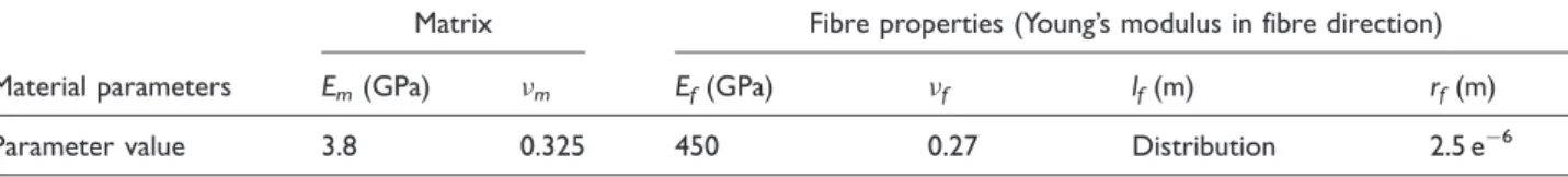
The first step was to validate the global elastic predic-tion using the micro-parameters shown in Table 9,
Figure 3. Effects of control factors on Young’s modulus. Figure 2. Stress and average relative temperature.
Figure 4. Effects of control factors on ultimate strain.
Figure 5. Effects of control factors on ultimate stress. Table 4. Mechanical properties of 90HMF40.
Material properties of 90HMF40 Ex (GPa) Ey (GPa) !r x(MPa) "rx (%) Tests 43.5$ 1.1 – 317.1$ 10.2 1.00 $ 0.07 Numerical model for comparison 45.5 20.0 – –
where lfand rfare the fibre length and radius,
respect-ively. A representative distribution of fibre length mea-sured (Figure 12). A representative distribution of orientation was also taken on the basis of the experi-mental data (Figure 13). Samples were cut and observed with a microscope to determine the distribu-tion of orientadistribu-tion by image analysis and computadistribu-tion.
Non-linear prediction
Once the elastic prediction was validated, we focused on the non-linear behaviour of the material. From the results of cyclic tensile tests, macroscopic isotropic hardening law parameters were determined (see Table 10) with the fit of the plastic curve determined by tensile tests (Figure 14). The matrix non-linear
behaviour was thus modelled. Effects of control factors are given in Figure 15.
Moreover, Fitoussi et al.40 criteria parameters were determined by Eshelby50for failure stresses (Table 10) by means of unidirectional laminate failure analysis.
Table 6. ANOVA results for strain.
Source of variation S DOF Variance Fcalc Risk Signif Contribution (%) Temperature 7.69039E" 06 2 3.8452E" 06 13.297088 0.0002123 Yes 49.15 Holding pressure 1.50503E" 07 2 7.52516E" 08 0.2602278 0.7734459 No 0.96 Holding time 3.72931E" 07 2 1.86466E" 07 0.6448173 0.5353254 No 2.38 Cooling time 1.6486E" 06 2 8.24298E" 07 2.8505095 0.0814323 No 10.54
Error 5.78352E" 06 20 2.89176E" 07 36.96
Total 1.56459E" 05 26 6.01767E" 07 100.00
ANOVA: analysis of variances; DOF: Degrees of freedom.
Table 5. ANOVA results for Young’s modulus.
Source of variation S DOF Variance Fcalc Risk Signif Contribution (%)
Temperature 6,253,891 2 3,126,946 2.697 0.092 No 16.9 Holding pressure 659,047 2 329,523 0.284 0.756 No 1.8 Holding time 4,824,197 2 2,412,098 2.080 0.151 No 13.1 Cooling time 1,971,676 2 985,838 0.850 0.442 No 5.3 Error 23,190,867 20 1,159,543 62.8 Total 36,899,678 26 1,419,218 100.0
DOF: Degrees of freedom; ANOVA: analysis of variances.
Table 7. ANOVA results for stress.
Source of variation S DOF Variance Fcalc Risk Signif Contribution (%)
Temperature 1174 2 587 7.94 0.00 Yes 40.13 Holding pressure 167 2 84 1.13 0.34 No 5.73 Holding time 18 2 9 0.12 0.89 No 0.60 Cooling time 87 2 44 0.59 0.56 No 2.98 Error 1479 20 74 50.56 Total 2925 26 113 100.00
ANOVA: analysis of variances; DOF: Degrees of freedom.
Table 8. Effects of injection parameters on tensile properties for 90HMF40. Injection parameters 90HMF40 Tmould E¼ /!r%/"r% Phold No effect thold No effect tcool No effect
The friction coefficient was assumed to take the clas-sical value of 0.3.
Finally, the prediction of the model was compared with experimental data obtained from monotonic ten-sile tests. As can be seen from Figure 16, there was fairly good agreement between the modeling prediction and the experimental data (error < 8%). It should be noted that the experimental data corresponded to the experimental design and thus had an unusually wide dispersion.
Figure 6. SEM image of fracture surface (debonding zone (a) and matrix plasticity (b)).
Figure 7. Damage vs. energy damage. Figure 9. Effects of control factors on damage parameterad.
Conclusions and perspectives
Thanks to a design of experiments, it has been possible to determine the effects of process parameters on
micro-structure and, thus, on mechanical properties.
Observation of fracture surfaces revealed non-linear phenomena responsible for material failure. Tensile tests and cyclic (load–unload) tensile tests gave an understanding of the scenarios of damage and
Figure 11. Behaviour of 90HMF40 during load–unload tensile tests.
Figure 10. Effects of control factors on damage parameter $d.
Figure 12. Fibre length distribution. Table 9. Model parameters input to Mori–Tanaka model.
Material parameters
Matrix Fibre properties (Young’s modulus in fibre direction) Em(GPa) %m Ef(GPa) %f lf(m) rf(m)
Parameter value 3.8 0.325 450 0.27 Distribution 2.5 e" 6
Table 10. Parameters of the matrix.
Hardening law Fitoussi criteria
Material parameters R0(MPa) Rcrit(MPa) g !Rn (MPa) #Rs (MPa) f
Parameter value 45$ 10 240$ 40 " 2100 $ 500 80.8$ 3 165$ 10 0.3
plasticity. Thanks to an infrared thermography analysis carried out during the tensile tests, the scenario was refined. A micromechanical model based on Mori– Tanaka homogenization theory was developed, featur-ing micro-damage and couplfeatur-ing with macro-plasticity, and gave a good prediction of quasi-static tensile test results. An extension to load–unload tensile tests is needed to check the model accuracy.
Possible perspectives include:
. Development of failure modelling of the short-fibre-reinforced composite and integration of the model into the computations.
. 3D microstructurally based modelling and
Simulation (with use of tomography).
. Behaviours temperature and time dependence of this carbon-fibre-reinforced PEEK.
. Simulation of deformation and damage, integration of matrix viscoelasticity into models, integration of plasticity at microscale, etc.
. Simulation of deformation and damage of this crys-talline material during fatigue and creep.
. Integration of more sophisticated crystal plasticity-based models into mechanical behaviour simulation. . Work on more advanced or enhanced interface
criteria.
Figure 16. Prediction and experimental data for monotonic tensile test.
Figure 14. Stress vs. plastic strain for quasi-static cycled tests.
Declaration of Conflicting Interests
The author(s) declared no potential conflicts of interest with respect to the research, authorship and/or publication of this article.
Funding
The author(s) received no financial support for the research, authorship and/or publication of this article.
References
1. Soutis C. Carbon fiber reinforced plastic in aircraft con-struction. Mater Sci Eng A 2005; 412: 171–176.
2. Denault J and Dumouchel M. Consolidation process of PEEK/carbon composite for aerospace applications. Adv Perform Mater 1998; 5: 83–96.
3. Grove S. Manufacture of polymer composites. Wiley encyclopedia of composites. Oxford: John Wiley & Sons, 2012.
4. Pickering SJ. Recycling thermoset composite materials. Wiley encyclopedia of composites. Oxford: John Wiley & Sons, 2012.
5. Sarasua JR, Remiro PM and Pouyet J. The mechanical behaviour of PEEK short fibre composites. J Mater Sci 1995; 30: 3501–3508.
6. Semadeni M, Zerlik H, Rossini P, et al. Injection mould-ing with high fiber volume fraction of carbon fiber reinforced Polyetheretherketone (PEEK) to increase mechanical properties. In: International SAMPE Europe conference, no. 19, Paris la De´fense, 22–24 April 1998, pp. 315–321. Niederglatt, Switzerland: SAMPE Europe. 7. Hoa S. Principles of the manufacturing of composite
materials. Lancaster, PA: DEStech Publications, Inc, 2009.
8. Thomason JL. The influence of fibre length, diameter and concentration on the strength and strain to failure of glass-fibre reinforced Polyamide 6,6. Compos A Appl Sci Manuf 2008; 39: 1618–1624.
9. Vincent M, Giroud T, Clarke A, et al. Description and modeling of fiber orientation in injection molding of fiber reinforced thermoplastics. Polymer 2005; 46: 6719–6725. 10. Kardos JL. Critical issues in achieving desirable mechan-ical properties for short fiber composites. Pure Appl Chem 1985; 57: 1651–1657.
11. Kanoute´ P, Boso DP, Chaboche JL, et al. Multiscale methods for composites: a review. Arch Comput Meth Eng 2009; 16: 31–75.
12. Tucker CL III and Liang E. Stiffness predictions for uni-directional short-fiber composites: review and evaluation. Compos Sci Tech 1999; 59: 655–671.
13. Cox HL. The elasticity and strength of paper and other fibrous materials. Br J Appl Phys 1952; 3: 72.
14. Rosen BW. Tensile failure of fibrous composites. AIAA J 1964; 2: 1985–1991.
15. Voigt W. Lehrbuch Der Kristallphysik. Stuttgart: B.G. Teubner, 1910.
16. Reuss A. Berechnung der Fließgrenze von Mischkristallen auf Grund der Plastizita¨tsbedingung fu¨r
Einkristalle. ZAMM J Appl Math Mech (Zeitschrift fu¨r angewandte Mathematik und Mechanik) 1929; 9: 49–58. 17. Reuss A. Beru¨cksichtigung der elastischen
Forma¨nder-ung in der Plastizita¨tstheorie. ZAMM J Appl Math Mech (Zeitschrift fu¨r angewandte Mathematik und Mechanik) 1930; 10: 266–274.
18. Hashin Z and Shtrikman S. A variational approach to the theory of the elastic behaviour of multiphase materials. J Mech Phys Solid 1963; 11: 127–140.
19. Lielens G, Pirotte P, Couniot A, et al. Prediction of thermo-mechanical properties for compression moulded composites. Compos A Appl Sci Manuf 1998; 29: 63–70. 20. Hill R. A self-consistent mechanics of composite
mater-ials. J Mech Phys Solid 1965; 13: 213–222.
21. Benveniste Y. A new approach to the application of Mori–Tanaka’s theory in composite materials. Mech Mater 1987; 6: 147–157.
22. Tandon GP and Weng GJ. The effect of aspect ratio of inclusions in the elastic properties of unidirectionally aligned composites. Polymer Compos 1984; 5: 327–333. 23. Thomasson JL and Vlug MA. Influence of fibre length
and concentration on the properties of glass fibre-rein-forced polypropylene: 1. Tensile and flexural modulus. Compos A Appl Sci Manuf 1996; 27: 477–484.
24. Fu SY and Lauke B. Effects of fiber length and fiber orientation distributions on the tensile strength of short-fiber-reinforced polymers. Compos Sci Tech 1996; 56: 1179–1190.
25. Kim JW and Lee DG. Fiber orientation state depending on the injection mold gate variations during FRP injec-tion molding. Key Eng Mater 2006; 321–323: 938–941. 26. Chou TW and Nomura S. Fibre orientation effects on the
thermoelastic properties of short-fibre composites. Fibre Sci Tech 1980; 14: 279–291.
27. Talbott MF, Springer GS and Berglund LA. The effects of crystallinity on the mechanical properties of PEEK polymer and graphite fiber reinforced PEEK. J Compos Mater 1987; 21: 1056–1081.
28. Thomasson JL. The influence of fibre length and concen-tration on the properties of glass fibre reinforced poly-propylene: 5. Injection moulded long and short fibre PP. Compos A Appl Sci Manuf 2002; 33: 1641–1652. 29. Boey FYC. Reducing the void content and its variability
in polymeric fibre reinforced composite test specimens using a vacuum injection moulding process. Polymer Test 1990; 9: 363–377.
30. El Kadi H and Denault J. Effects of processing condi-tions on the mechanical behavior of carbon-fiber-reinforced PEEK. J Thermoplast Compos Mater 2001; 14: 34–52.
31. Park K and Kim YS. Effects of mold temperature on mechanical properties of an injection-molded part with microfeatures. J Polymer Eng 2009; 29: 135–153. 32. Pechulis M and Vautour D. The effect of thickness
on the tensile and impact properties of reinforced thermoplastics. J Reinforc Plast Compos 1998; 17: 1580–1586.
33. Sarasua JR, Remiro PM and Pouyet J. Effects of thermal history on mechanical behavior of PEEK and its short-fiber composites. Polymer 1996; 17: 468–477.
34. Chen CH and Cheng CH. Effective elastic moduli of mis-oriented short-fiber composites. Int J Solid Struct 1996; 33: 2519–2539.
35. Termonia Y. Structure-property relationships in short-fiber-reinforced composites. J Polymer Sci B Polymer Phys 1994; 32: 969–979.
36. Christensen RM, Schantz H and Shapiro J. On the range of validity of the Mori–Tanaka method. J Mech Phys Solid 1992; 40: 69–73.
37. Pierard O, Friebel C and Doghri I. Mean-field homogen-ization multi-phase thermo-elastic composites: a general framework and its validation. Compos Sci Tech 2004; 64: 1587–1603.
38. Vu-Khanh T and Denault J. Effect of molding param-eters on the interfacial strength in PEEK/carbon compos-ites. J Reinforc Plast Compos 1993; 12: 916–931. 39. Hour KY and Sehitoglu H. Damage development in a
short fiber reinforced composite. J Compos Mater 2003; 27: 782–805.
40. Fitoussi J, Gao G and Baptiste D. Determination of a tridimensional failure criterion at the fibre/matrix inter-face of an organic-matrix/discontinuous-reinforcement composite. Compos Sci Tech 1996; 56: 755–760.
41. ASTM D3641 – 10a. Standard practice for injection molding test specimens of thermoplastic molding and extrusion materials. West Conshohocken, PA: ASTM International, 2010.
42. Sabre T. Plans d’expe´riences – Me´thode de Taguchi. Techniques de l’Inge´nieur, F1006 2007.
43. Wesselman MH. Impact of the moulding conditions on the properties of short fibre reinforced high performance thermoplastic parts. Thesis, Universite´ de Toulouse, Toulouse, 2003.
44. Saint-Martin G, Schmidt F, Devos P, et al. Voids in short fibre-reinforced injection-moulded parts: density control vs. mass control. Polymer Test 2003; 22: 947–953. 45. Saint-Martin G. E´tude typologique des de´fauts structuraux
ge´ne´re´s au cours de la mise en forme par injection de com-posites a` matrice polyme`re thermostable renforce´s par fibres
de verre courtes. PhD Thesis, Universite´ de Toulouse, Toulouse, 2003.
46. Haramburu E. Approche inte´gre´e du dimensionnement me´canique de structures en composite injecte´ avec fibres courtes: une interface entre injection et calcul de structure. PhD Thesis, Universite´ de Toulouse, Toulouse, 2003. 47. Bessard E, De Almeida O and Bernhart G. Melt state
behaviour of PEEK and processing window interpret-ation for fast compression moulding process. In: Proceedings of international conference on advances in materials and processing technologies, Paris, France, 24–27 October 2010.
48. NF ISO 5272. De´termination des proprie´te´s en traction -Partie 2: Conditions d’essai des plastiques pour moulage et extrusion. 2012. Afnor, 11 Rue Francis De Pressense´ – 93571 La Plaine Saint Denis Cedex France.
49. Mori T and Tanaka K. Average stress in matrix and average elastic energy of materials with misfitting inclu-sions. Acta Metallurgica 1973; 21: 571–574.
50. Eshelby JD. The determination of the elastic field of an ellipsoidal inclusion and related problems. Proc Roy Soc Lond Math Phys Sci 1957; 241: 376–396.
51. Meraghni F, Desrumaux F and Benzeggagh ML. Implementation of a constitutive micromechanical model for damage analysis in glass mat reinforced composite structures. Compos Sci Tech 2002; 62: 2087–2097.
52. Lachaud F. De´laminage de mate´riaux composites a` fibres de carbone et a` matrices organiques: E´tude nume´rique et expe´rimentale, suivi par e´mission acoustique. French PhD Thesis, Toulouse University, Toulouse, 1997.
53. Friedrich K, Walter R, Voss H, et al. Effect of short fibre reinforcement on the fatigue crack propagation and frac-ture of PEEK-matrix composites. Composites 1986; 17: 205–216.
54. Kim JK and Gao SL. Interface adhesion and interlami-nar fracture resistance of carbon/PEEK composites influ-enced by cooling rate. Key Eng Mater 2000; 183–187: 1063–1068.