HAL Id: hal-01723632
https://hal.archives-ouvertes.fr/hal-01723632
Submitted on 5 Mar 2018
HAL is a multi-disciplinary open access
archive for the deposit and dissemination of
sci-entific research documents, whether they are
pub-lished or not. The documents may come from
teaching and research institutions in France or
abroad, or from public or private research centers.
L’archive ouverte pluridisciplinaire HAL, est
destinée au dépôt et à la diffusion de documents
scientifiques de niveau recherche, publiés ou non,
émanant des établissements d’enseignement et de
recherche français ou étrangers, des laboratoires
publics ou privés.
Comparative study of ” Phoenix ” reflectarray
phase-shifting cells
T. Makdissy, R. Gillard
To cite this version:
T. Makdissy, R. Gillard.
Comparative study of ” Phoenix ” reflectarray phase-shifting cells.
LAPC2017, Nov 2017, Loughborough, United Kingdom. �hal-01723632�
Comparative study of “Phoenix” reflectarray phase-shifting cells
T Makdissy*, R Gillard
†*TICKET Lab., Antonine University, 40016 Hadat-Baabda, Lebanon, [email protected], †IETR, INSA of Rennes,
UMR CNRS 6164, Rennes 35708, France, Raphaë[email protected]
Keywords: phoenix, reflectarray, wideband.
Abstract
This paper presents a fair comparison between four different “Phoenix” phase-shifting cells that can be found in the literature. This comparison is mainly based on the frequency dispersion and on the bandwidth where the maximum differential phase shift is less than 90°. Then, an alternative “Phoenix” unit-cell of reduced size offering an enhanced bandwidth is proposed.
1 Introduction
Reflectarrays first appeared in 1963 [1], but their true interest was revealed in the late 1980s through printed technology [2]. Over the last three decades, these antennas have been widely studied. They offer the possibility of forming complex radiation patterns with relative simplicity, low cost, low losses and reduced volume [3].
This type of antenna has long suffered from three main defects:
- The insufficient phase range (less than 360°) provided by the unit cell [4], which is mainly due to size of the lattice. - The limited bandwidth that has long confined reflectarrays to narrow band applications. For small panels, this is mainly related to the narrow band behavior of the unit cell constituting the array [5].
- The non-regularity of the cell geometry on the surface of the array which can lead to degradation of the radiation pattern [6], especially at the transition between two extreme geometries, when a new phase cycle begins.
Several solutions based on multiple resonators have been proposed in the past years in order to enhance the phase range provided as well as the bandwidth of the reflectarray. Some use multilayer substrates [7,8], others use single layer substrate [9,10]. However, these solutions don’t allow overcoming the problem of the non-regular geometry of the cell.
In 2011, a phase-shifting cell using two complementary slot resonances, one with a low dispersion and the other with a higher dispersion was presented [11]. It is called the "Phoenix" cell. The slots are concentric etched in a ground plane on a single layer substrate. The main interest of this cell is the smooth variation of its geometry, which offers the possibility to loop back to the initial state after a complete phase cycle of 360°. This can be done without drastic changes on the radiating aperture. Consequently, it appears as a good candidate for solving the problem of the non-regular
geometry. However, this cell was not tested on a real reflectarray.
Few years later, two alternative topologies derived from the original “Phoenix” cell were proposed. The first one [12], designed to operate at 10GHz, was tested on a 225-element reflectarray fed with a linearly polarized Vivaldi antenna. Measurements show a 1-dB gain bandwidth of 29%. The second one [13], designed to operate on a single linear polarization metal-only antenna at 12.5GHz, was tested on a circular reflectarray of 516mm in diameter. Measurements show a 1-dB gain bandwidth of 12.8%.
In 2016, a new “Phoenix” cycle was proposed [14]. It involves a metallic cross with a capacitive effect and then a metallic grid with an inductive effect. It has been demonstrated that the inductance of the grid was not strong enough in order to bridge the required 360° of phase range. However the cell shows a broadband behavior since both elements were used out of the resonance. Three different techniques were proposed in order to increase the inductive effect of the grid and to complete the phase range. A 1877-element reflectarray (with non-optimal illumination) was fabricated with the technique compatible with a single-substrate fabrication process. It operates at 13GHz in dual linear polarization. The measured 1-dB gain bandwidth was 11.3%.
In this paper, a comparison in terms of bandwidth and phase dispersion with the frequency between the four existing “Phoenix” cells will be carried out. Then a new sub-wavelength “Phoenix” cell inspired from [11] and offering better performance will be presented.
2 “Phoenix” cells performance assessments
This section aims to assess the performance of four different “Phoenix” cells. This assessment is based on the frequency bandwidth (in %) for which the maximum differential phase shift (i.e. the maximum phase variation) is less than 90°. 2.1 The original “Phoenix” cell
The original “Phoenix” cell [11] is 12mm in size (i.e. 0.66λ0
at 16.5GHz). It consists of a square ring slot with length LS
and width WS. A metallic ring with length LR and width WR is
inserted into the slot, splitting it into two smaller resonating slots of complementary size. The slots are etched in a metallic layer separated by a 6mm air gap (εr=1) from the ground
plane. The length LR of the metallic ring controls the reflected
phase. The cell was simulated in an infinite periodic array, illuminated with plane wave under normal angle of incidence. Simulations show that the cell offers a nearly 360° of phase
range at the central frequency of 16.5GHz with a linear and parallel variation of the phase. Moreover, the frequency dispersion is less than 30°/GHz between 15GHz and 18GHz. Hence, the maximum differential phase shift is 90° over 18% of bandwidth.
It is worth to mention that the frequency dispersion would have been greater if a substrate with a different relative permittivity had been in use (εr≠1). This would certainly
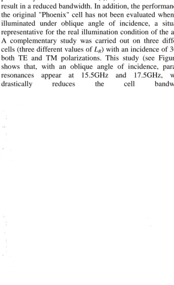
result in a reduced bandwidth. In addition, the performance of the original "Phoenix" cell has not been evaluated when it is illuminated under oblique angle of incidence, a situation representative for the real illumination condition of the array. A complementary study was carried out on three different cells (three different values of LR) with an incidence of 30° in
both TE and TM polarizations. This study (see Figure 1) shows that, with an oblique angle of incidence, parasitic resonances appear at 15.5GHz and 17.5GHz, which drastically reduces the cell bandwidth.
Figure 1: Effect of a 30° incidence on the phase responses of the original “Phoenix” cell: (a) TE mode, (b) TM mode. 2.2 The first derivative
A first cell that derives from the original “Phoenix” cell was proposed in [12]. It consists of a circular patch of radius r1
surrounded with two concentric ring of radius r3 and r4. The
cell size is 12mm (i.e. 0.4λ0 at 10GHz). It is printed on a
1.6mm thick substrate of relative permittivity εr=4.4,
suspended 8mm above a ground plane. The reflected phase is controlled by the radius r3 of the inner ring. The cell was
simulated in an infinite periodic array illuminated with plane wave under normal angle of incidence. Simulations show that the cell offers a 360° of phase range at the central frequency of 10GHz, and the different phase curves are quasi-parallel between 8GHz and 11GHz. The maximum frequency dispersion of the phase is obtained for r3=3mm and it is equal
70°/GHz. Moreover, this cell demonstrates an acceptable behavior with an oblique angle of incidence up to 30° in both TE and TM polarizations at 10GHz. A thorough analysis of the phase responses shows that the maximum differential phase shift of 90° is obtained between 9.5GHz and 11GHz which results in a 14.6% of bandwidth.
2.3 The second derivative
A second cell was proposed in [13]. It has the same geometry as the original “Phoenix” [11]. The only difference lies in the use of a connecting stub in order to unite the patch and the metallic loops into one piece since the cell is designed for a single linear polarization metal-only reflectarray antenna. The cell size is 12mm (i.e. 0.5λ0 at 12.5GHz). The separation
between the upper metallic layer and the ground plane is 4mm. The control of the reflected phase is done with the middle loop length L. The phase range provided by the cell when illuminated with a normal angle of incidence is 360°. The maximum frequency dispersion of the phase is obtained for L=7.5mm and it is equal 80°/GHz. Hence, the maximum differential phase shift is 90° over 10% of bandwidth. In addition, the proposed cell demonstrates an acceptable behavior under oblique angle incidence at the central frequency (i.e. a 30° incidence results only in a 20° of phase shift).
2.4 The “Phoenix” cell with inductive loading
A new “Phoenix” approach was proposed in [14]. The geometric cycle involves two complementary parts. The first part consists in growing two crossed dipoles of size 2w until crosses in successive cells touch each other and form a metallic grid. Then, the second part consists in narrowing the width w of the metallic grid, which increases the size of the defined square apertures. The cell size is 8mm (i.e. 0.36λ0 at
13.5GHz). It is printed on a 3.175mm thick Duroïd substrate of relative permittivity εr=2.2. The cell was simulated using
the infinite periodic boundary conditions, illuminated with a plane wave under normal angle of incidence. It offers a phase range of only 305° with a linear and parallel variation of the phase over a large bandwidth. A third part was added to the cycle. It consists to add a meander to the thinnest metallic grid in order to increase the inductive effect and to bridge the 55° gap in the phase range. Simulations show that using a meander of length m=5mm permits to complete the 360° phase range at 13.5GHz. This was done at the expense of the frequency dispersion which increases with m and reaches 45°/GHz. Furthermore, under a 30° angle of incidence, a complete 360° is provided with a quite good parallelism between the phase responses from 12GHz to 15GHz. A thorough analysis of the phase responses shows that the maximum differential phase shift of 90° is obtained between 12.5GHz and 15GHz which results in an 18% of bandwidth.
3 New “Phoenix” cell
In this section, a new derivative from the original “Phoenix” cell is proposed. The cell is shown in Figure 2. It consists of two concentric annular metallic rings of 0.1mm in width. The
outer ring (of fixed length) surrounds the cell, and the inner one of variable size L is used to control the reflected phase. The cell size is 8mm (0.33λ0 at 12.5GHz). It is printed on a
1.575mm Duroïd substrate of relative permittivity εr=2.2,
suspended 5mm above a ground plane. Figure 3 shows the proposed “Phoenix” cycle. It begins with only the outer ring surrounding the cell. This results in a square aperture wide enough to provide a phase response with a smooth variation and small frequency dispersion. Then, the inner ring (with a small value L) is introduced in the center of the cell. This splits the square aperture into two slots of complementary size: a narrow square slot with a sharp resonance at high frequencies (outside the band) surrounded by a wide annular slot with a smooth resonance at low frequencies (inside the band). Increasing the size L of the inner ring increases the length of both slots and pushes the resonances toward the lower frequencies. Simultaneously, the lowest resonance becomes sharper and the highest resonance is smoothened. Finally, the cycle ends with the complete vanishing of the metallic ring, which permits to loop back to the initial state. In order to assess the performance of the new cycle, the cell is simulated using HFSS® electromagnetic simulator. It is placed in an infinite periodic array and illuminated with a plane wave under normal angle of incidence. Simulations show that cycle is able to provide a complete 360° of phase range at 12.5GHz with a linear and parallel variation of the phase between 11GHz and 15GHz (see Figure 4). The maximum frequency dispersion at the central frequency is 42°/GHz, and the maximum differential phase shift of 90° is obtained for L=3mm between 11.25GHz and 13.75GHz, hence a bandwidth of 20%.
In order to evaluate the performance of the cell inside the array, it is now simulated with the Floquet boundary conditions under a 30° angle of incidence. Figure 5 shows that this oblique incidence results in undesired resonances for frequencies above 15GHz in TM polarization. The bandwidth for which the maximum phase shift is 90° is maintained between 11.25GHz and 13.75GHz which demonstrates the satisfactory behavior of this new derivative.
Figure 2: (a) Top view of the cell, (b) Side view of the cell.
Figure 3: Proposed “Phoenix” cycle.
Figure 4: Reflected phase versus frequency for the new cell under a normal angle of incidence.
Figure 5: Reflected phase versus frequency for the new cell under a 30° angle of incidence: (a) TE mode, (b) TM mode.
4 Comparison of the different “Phoenix” cells
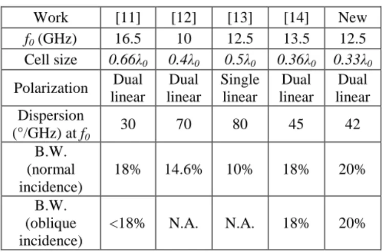
Work [11] [12] [13] [14] New f0 (GHz) 16.5 10 12.5 13.5 12.5 Cell size 0.66λ0 0.4λ0 0.5λ0 0.36λ0 0.33λ0 Polarization Dual linear Dual linear Single linear Dual linear Dual linear Dispersion (°/GHz) at f0 30 70 80 45 42 B.W. (normal incidence) 18% 14.6% 10% 18% 20% B.W. (oblique incidence) <18% N.A. N.A. 18% 20%
Table 1 permits to compare the different cells:
The original “Phoenix” cell [11], based on two annular slots of complementary sizes, offers 18% of bandwidth when illuminated with a normal angle of incidence. This bandwidth is drastically reduced for an oblique angle of incidence due to parasitic resonances (as explained in section 2).
The cell proposed in [12] (inspired from [11]) also shows an acceptable bandwidth (~15%) for a normal incidence. However, the effect of the oblique incidence on the bandwidth was not shown.
In [13] the cell offers a 10% of bandwidth under a normal angle of incidence. But the real interest of the cell resides in the fact that it is designed for a metal-only reflectarray antenna. Here also the effect of the oblique angle of incidence on the bandwidth was not shown.
In [14], a new sub-wavelength “Phoenix” cell was presented. It is based on the consecutive use of two different elements in the same cycle. These elements are operating out of their resonances, which provides a 18% bandwidth under both normal and oblique angle of incidence.
The sub-wavelength cell deriving from [11] proposed in this paper demonstrates an enhanced bandwidth of 20% for both normal and oblique angle of incidence. This demonstrates that this new cell is a good candidate for dual linear polarization wideband reflectarrays.
5 Conclusion
This paper compares the performance of four different “Phoenix” cells proposed in the past few years. The criterion for the performance evaluation is the cell bandwidth for which the maximum differential phase shift is 90°. The comparison shows that 18% of bandwidth is offered by the sub-wavelength “Phoenix” cell using two complementary elements out of their resonances. This bandwidth is preserved even for a 30° angle of incidence. Then, a new sub-wavelength “Phoenix” cell based on two concentric slots of complementary size is proposed. Simulations show that 20% of bandwidth is provided for both normal and oblique illumination conditions.
References
[1] D. C. Berry, R. G. Malech, and W. A. Kennedy, “The Reflectarray Antenna”, IEEE Transactions on Antennas
and Propagation, volume 11, pp. 645-651, (1963).
[2] R. E. Munson, and H. Haddad, “Microstrip reflectarray for satellite communication and RCS enhancement and reduction”, U.S. patent 4,684,952, Washington, D.C., (1987).
[3] D. M. Pozar, S. D. Targonski, and R. Pokuls, “A shaped-beam microstrip patch reflectarray”, IEEE
Transactions on Antennas and Propagation, volume 47,
pp. 1167–1173, (1999).
[4] D. M. Pozar, and T. A. Metzler, “Analysis of a reflectarray antenna using microstrip patches of variable size”, Electronics Letters, volume 29, pp. 657-658, (1993).
[5] D. M. Pozar, “Bandwidth of reflectarrays”, Electronics
Letters, volume 39, pp. 1490-1491, (2003).
[6] H. Legay, D. Bresciani, E. Labiole, R. Chiniard, and R. Gillard, “A multifacets composite panel reflectarray antenna for a space contoured beam antenna in Ku band”, Progress in Electromagnetics Research B, volume 54, pp. 1–26, (2013).
[7] J. A. Encinar, J. A. Zornoza, “Broadband design of three-layer printed reflectarrays”, IEEE Transactions on
Antennas and Propagation, volume 51, pp. 1662–1664,
(2003).
[8] E. Carasco, J. A. Encinar, M. Barba, “Bandwidth improvement in large reflectarrays by using true-time delay”, IEEE Transactions on Antennas and Propagation, volume 56, pp. 2496–2503, (2008).
[9] M. R. Chaharmir, J. Shaker, H. Legay, “Broadband design of a single layer large reflectarray using multi cross loop elements”, IEEE Transactions on Antennas
and Propagation, volume 57, pp. 3363–3366, (2009).
[10] A. Vosoogh, K. Keyghobad, A. Khaleghi, S. Mansouri “A high-efficiency Ku-band reflectarray antenna using single-layer multiresonance elements”, IEEE Antennas
and Wireless Propagation Letters, volume 13, pp. 891–
894, (2014).
[11] L. Moustafa, R. Gillard, F. Peris, R. Loison, H. Legay, and E. Girard, “The Phoenix Cell: A New Reflectarray Cell with Large Bandwidth and Rebirth Capabilities”,
IEEE Antennas and Wireless Propagation Letters,
volume 10, pp. 71-74, (2011).
[12] C. Tian, Y. C. Jiao, and W. Liang, “A Broadband Reflectarray Using Phoenix Unit Cell”, Progress In
Electromagnetics Research Letters, volume 50, pp.
67-72, (2014).
[13] R. Deng, F. Yang, S. Xu, and M. Li, “A Low-Cost Metal-Only Reflectarray Using Modified Slot-Type Phoenix Element with 360° Phase Coverage”, IEEE
Transactions on Antennas and Propagation, volume 64,
pp. 1556–1560, (2016).
[14] T. Makdissy, R. Gillard, E. Fourn, M. Ferrando-Rocher, E. Girard, H. Legay, and L. Le Coq, “‘Phoenix’ reflectarray unit cell with reduced size and inductive loading”, IET Microwaves, Antennas & Propagation, volume 10, pp. 1363–1370, (2016).